8
Sicurezza
Istruzioni di sicurezza
Assicurarsi che il personale incaricato di installare e
operare sul termostato:
• sia tecnicamente qualicato e competente;
• rispetti pedissequamente queste istruzioni
d’assemblaggio.
L’uso improprio di questi dispositivi potrebbe determinare
pericolo per:
• vita e arti
• attrezzatura e altri beni dell’operatore
• corretto funzionamento dell’attrezzatura.
Le istruzioni di sicurezza di questo manuale sono riportate in
tre diversi formati per sottolineare informazioni importanti.
Note di sicurezza sul funzionamento dell’apparecchiatura
L’installazione elettrica è soggetta alle leggi nazionali di
sicurezza.
È mandatorio collegare il cavo di messa a terra per motivi
di sicurezza.
Questa informazione indica un particolare pericolo per la vita e
la salute. Ignorare questo tipo di avvertimento potrebbe causare
ferite gravi o fatali.
Il regolamento antincendio deve essere rigorosamente rispettato.
Questa informazione indica un particolare pericolo per l’attrez-
zatura o altri beni dell’operatore. Ferite gravi o fatali non sono da
escludersi.
L’installazione, la connessione elettrica e il montaggio del
dispositivo devono essere effettuati da personale qualicato e
solo secondo questo manuale di istruzione.
È responsabilità dell’utente assicurarsi che il dispositivo sia
utilizzato per la sua corretta applicazione.
Per questioni di sicurezza, evitare usi non autorizzati o impropri.
Questa nota offre informazioni importanti o speciche sull’attrez-
zatura o su come operarvi.
AVVERTIMENTO
AVVERTIMENTO
ATTENZIONE
ATTENZIONE
NOTA
Descrizione del prodotto
Installazione
Leggere attentamente questo manuale d’istruzione prima di
mettere in funzione il dispositivo.
AVVERTIMENTO
Le prescrizioni indicate in questo manuale devono essere rigoro-
samente rispettate pena il rischio di guastare l’accessorio.
AVVERTIMENTO
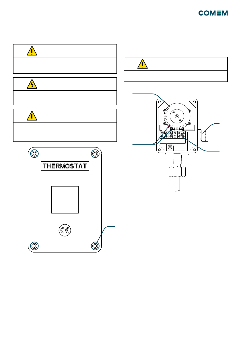
TWM 7284 / TWM 7287
Questi dispositivi misurano la temperatura dell’olio all’in-
terno di trasformatori, reattori e apparecchiature similari.
Contatti regolabili alla temperatura desiderata forniscono
segnali di allarme o sgancio. Non è presente alcun qua-
drante in grado di visualizzare la temperatura misurata.
Montaggio dell’accessorio
L’accessorio deve essere installato sul trasformatore in
accordo alla tipologia di ssaggio selezionata:
• il modello 7284 è sprovvisto di capillare; il montaggio
viene realizzato in concomitanza con la connessione del
bulbo
• il modello 7287 è provvisto di capillare; può essere
assemblato tramite vite rigida oppure sospensione
elastica in base al tipo selezionato.
Le dimensioni di ciascuna tipologia di ssaggio sono
indicate nei disegni nell’appendice A.
L’accessorio deve essere installato verticalmente. L’instal-
lazione deve essere fatta in modo tale da evitare vibrazioni
e/o campi elettromagnetici oltre i limiti previsti dagli
standard di riferimento.
Capillare (solo per modello 7287)
Srotolare il capillare evitando attorcigliamenti e loop.
Non tagliare, accorciare, tirare o piegare il capillare. Non
movimentare l’accessorio attraverso il capillare. Arrotolare
il capillare in eccesso con un diametro minimo di 40cm.
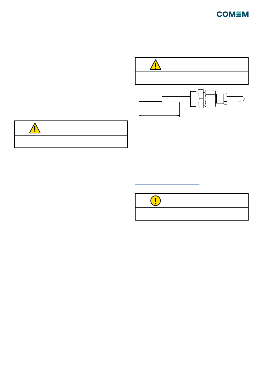
Bulbo
Inserire il bulbo all’interno dell’apposito pozzetto presente
sul trasformatore (in accordo a DIN42554 o similare) il
quale deve essere preventivamente riempito con l’olio del
trasformatore (in caso di pozzetto DIN42554, la quantità
minima di olio deve essere di 80ml).
TERMOSTATO TMW