Comnet CNFE1CL1MC User manual

INS_CNFE1CL1MC(-M)_REV–
01/27/10
PAGE 1
INSTALLATION AND OPERATION MANUAL
CNFE1CL1MC(-M)
FAST ETHERNET OVER VDSL (EoVDSL)
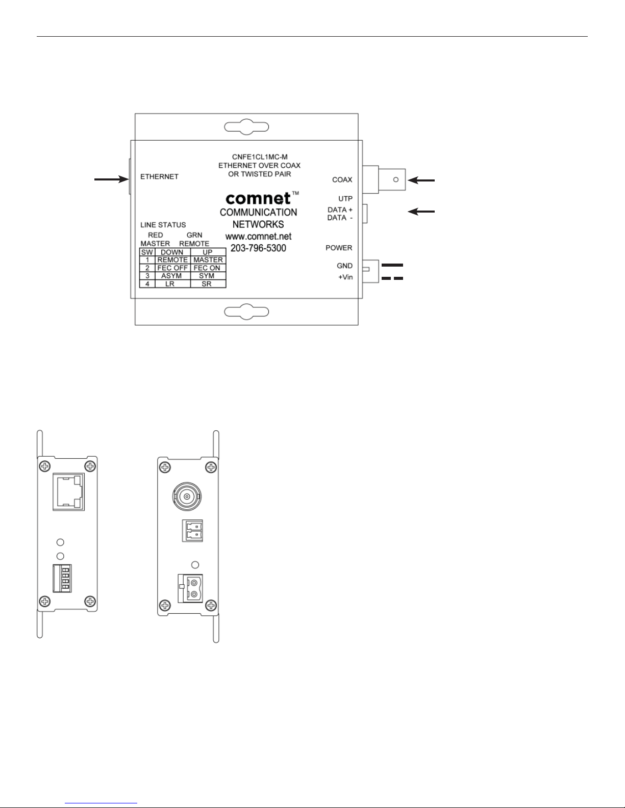
The ComNet™CNFECL1MC(-M) is an environmentally hardened modem that
supports Ethernet over twisted pair or coaxial cable. The devices use VDSL
(EoVDSL) technology to support data rates up to 90 Mbs. Ethernet data may be
transmitted over a telephone-grade twisted copper pair, legacy serial cabling
or standard 75Ωcoaxial cable circuits. These modems allow for upgrading of
a legacy twisted copper or coaxial cable plant for use with Ethernet rather than
installing new network cabling.
The fastest usable data rate is automatically selected, depending upon
the transmission distance and cable quality. The CNFECL1MC(-M) may be
deployed in most out-of-plant installations, such as those found in intelligent
transportation systems and factory automation/control applications. LED status
indicators are provided for rapidly ascertaining the operating status of the
modem and the link.
See Figures 1 – 8 for complete installation details.
The CNFE1CL1MC standard size unit may be directly plugged into the ComNet
Rack (Part C1) or operated as a standalone module. The CNFE1CL1MC-M
small size unit operates as standalone module only. See Page 5 for mounting
instructions.

INS_CNFE1CL1MC(-M)_REV–
01/27/10
PAGE 2
NOTE: Remove Electrical Connector for Rack Mount Units
COAX (75Ω)
COPPER PAIR
CAT5e/6
BLACK
BLACK WITH WHITE STRIPE
FIGURE 2 – CNFE1CL1MC STANDARD SIZE UNIT
FIGURE 1 – CNFE1CL1MC STANDARD SIZE UNIT
INSTALLATION AND OPERATION MANUAL CNFE1CL1MC(-M)
REAR PANELFRONT PANEL
TECH SUPPORT: 1.888.678.9427
INS_CNFE1CL1MC(-M)_REV–
01/27/10
PAGE 3
COAX (75Ω)
COPPER PAIR
CAT5e/6
BLACK
BLACK WITH WHITE STRIPE
FIGURE 3 – CNFE1CL1MC-M SMALL SIZE UNIT
FIGURE 4 – CNFE1CL1MC-M SMALL SIZE UNIT
INSTALLATION AND OPERATION MANUAL CNFE1CL1MC(-M)
REAR PANELFRONT PANEL
TECH SUPPORT: 1.888.678.9427
INS_CNFE1CL1MC(-M)_REV–
01/27/10
PAGE 4
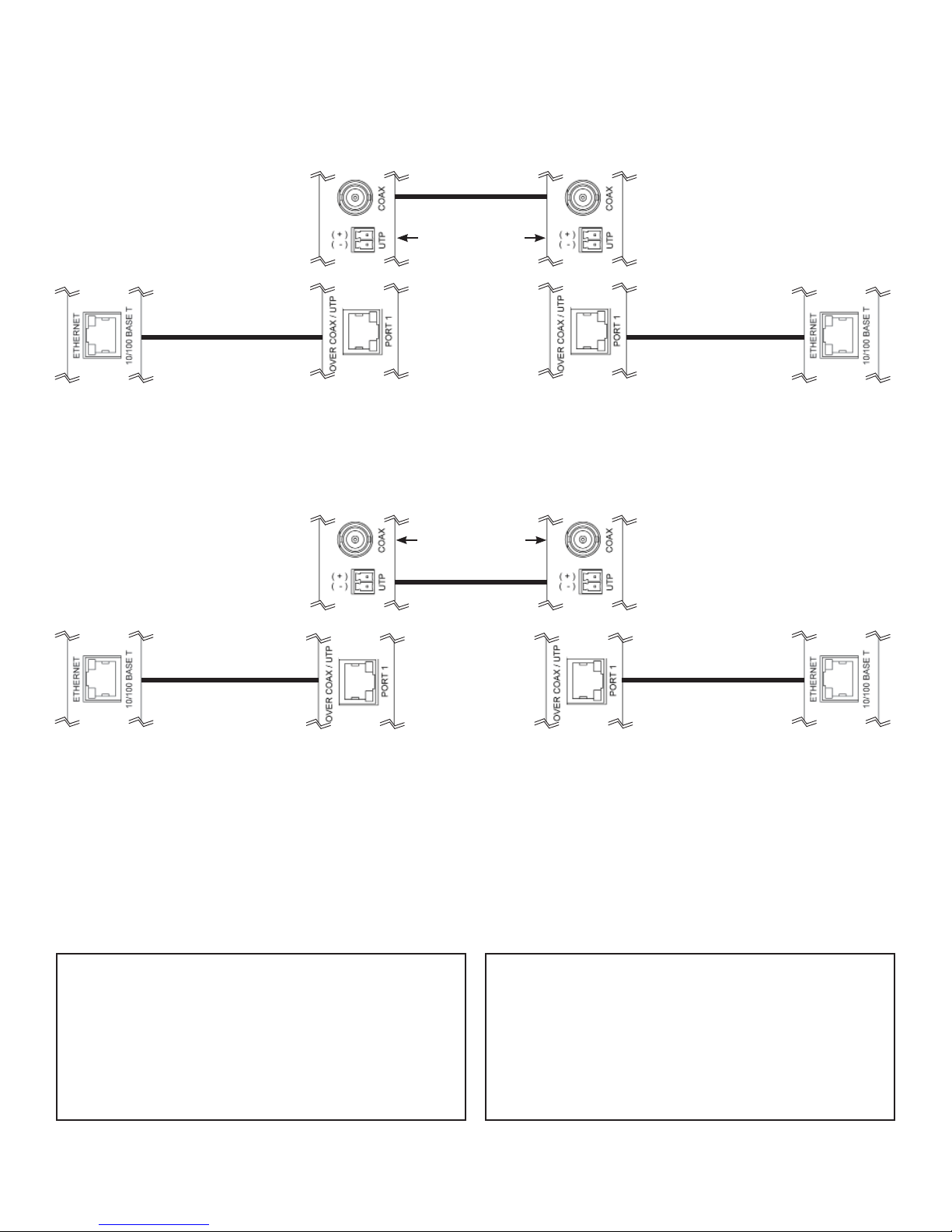
FIGURE 5 – POSSIBLE ETHERNET CONFIGURATIONS
FIGURE 6 – DISTANCE VS. SPEED
Ethernet IEEE 802.3
Network Element
Ethernet IEEE 802.3
Network Element
Ethernet IEEE 802.3
Network Element
Ethernet IEEE 802.3
Network Element
CNFE1CL1MC(-M)
(Master*)
CNFE1CL1MC(-M)
(Master*)
CNFE1CL1MC(-M)
(Remote)
CNFE1CL1MC(-M)
(Remote)
CAT5e/6 with
RJ45 Connections
100m (328ft)
CAT5e/6 with
RJ45 Connections
100m (328ft)
CAT5e/6 with
RJ45 Connections
100m (328ft)
CAT5e/6 with
RJ45 Connections
100m (328ft)
Coaxial (75Ω)
Copper Pair
Ethernet IEEE 802.3 Network Element determined by user.
No Connection
No Connection
OR
* Master unit located at video source.
Line Side Port 2:
Coax connector: BNC
Impedance: 75 ohm coax
Throughput: (Down Stream / Up Stream)
250 ft (76 m) 91 Mbps / 84 Mbps
500 ft (152 m) 86 Mbps / 82 Mbps
1000 ft (305 m) 65 Mbps / 69 Mbps
1500 ft (457 m) 40 Mbps / 52 Mbps
Line Side Port 1:
UTP connector: Screw Terminal Block
Cable: Telephone grade 19 to 26 AWG (one twisted pair)
Throughput: (Down Stream / Up Stream)
1000 ft (305 m) 70 Mbps / 65 Mbps
2500 ft (762 m) 26 Mbps / 17 Mbps
5000 ft (1524 m) 16 Mbps / 1 Mbps
7500 ft (2286 m) 5 Mbps / 0.5 Mbps
10,000 ft (3048 m) 1 Mbps / 0.25 Mbps

INS_CNFE1CL1MC(-M)_REV–
01/27/10
PAGE 5
FIGURE 8 – SWITCH SETTINGS
FIGURE 7 – LED INDICATORS
SWITCH DOWN (ON) UP (OFF) DEFAULT SETTING
1 Remote Master One ON, one OFF as a pair
2 Forward Error Correction Off Forward Error Correction On ON
3 Asymmetrical Data Symmetrical Data ON
4 Long Reach > 1000ft (305m) Short Reach < 1000ft (305m) ON
LINE STATUS (STAT)
RED MASTER (M/RD) or
GRN REMOTE (R/GN) POWER
GREEN Line side activity Remote Configuration Unit powered up
RED – Master Configuration –
OFF No activity Unit powered down
LED STATUS Low Constant Flashing Fast Constant Flashing On Intermittent Flashing
UNIT STATUS Idle (Line Is Not Connected) Master/Remote Negotiating Idle (Line Is Connected) Data Flow

INS_CNFE1CL1MC(-M)_REV–
01/27/10
PAGE 6
© 2010 Communications Networks Corporation. All Rights Reserved. “ComNet” and the “ComNet Logo” are registered trademarks of Communication Networks, LLC.
3 CORPORATE DRIVE | DANBURY, CT 06810 | USA
T: 203.796.5300 | F: 203.796.5303 | TECH SUPPORT: 1.888.678.9427 | INFO@COMNET.NET
8 TURNBERRY PARK ROAD | GILDERSOME | MORLEY | LEEDS, UK LS27 7LE
T: +44 (0)113 307 6400 | F: +44 (0)113 253 7462 | INFO-EUROPE@COMNET.NET
MECHANICAL INSTALLATION INSTRUCTIONS
FIGURE A
Dimensions are for a standard ComNet™ one slot module
.156 [3.96 mm]
.313 [7.95 mm]
INSTALLATION CONSIDERATIONS
This fiber-optic link is supplied as a Standalone/Rack module. Units
should be installed in dry locations protected from extremes of
temperature and humidity.
C1-US, C1-EU, C1-AU OR C1-CH CARD CAGE RACKS
CAUTION: Although the units are hot-swappable and may be installed
without turning power off to the rack, ComNet recommends that
the power supply be turned off and that the rack power supply
is disconnected from any power source. Note: Remove electrical
connector before installing in card cage rack.
1. Make sure that the card is oriented right side up, and slide it into
the card guides in the rack until the edge connector at the back
of the card seats in the corresponding slot in the rack’s connector
panel. Seating may require thumb pressure on the top and bottom
of the card’s front panel.
CAUTION: Take care not to press on any of the LEDs.
2. Tighten the two thumb screws on the card until the front panel of
the card is seated against the front of the rack.
WARNING: Unit is to be used with a Listed Class 2 or LPS power supply rated
9-12 VDC @ 1A.
IMPORTANT SAFEGUARDS:
A) Elevated Operating Ambient - If installed in a closed or multi-unit rack
assembly, the operating ambient temperature of the rack environment may
be greater than room ambient. Therefore, consideration should be given to
installing the equipment in an environment compatible with the maximum
ambient temperature (Tma) specified by the manufacturer.
B) Reduced Air Flow - Installation of the equipment in a rack should be such
that the amount of air flow required for safe operation of the equipment is
not compromised.
This manual suits for next models
2
Table of contents


