Compact Electric CDMR-51 User manual

DIGITAL LINE MONITORING RELAY
CDMR-51
1100 Vienna, DOERENKAMPGASSE 7
TEL.: + 43 / 1 / 815-12-71-0 or + 43 / 1 / 815-51-74-0
FAX.: + 43 / 1 / 813-64-21-21
homepage: http://www.compactelectric.at

Line Monitoring Relay CDMR-51 / User Manual Page 2
CDMR51e_man_A11.doc
Index:
Spezifications ….. ………………………..………………………Page 3
Terminal and wiring diagram (Abb.1) …………………………. Page 4
Configuring the relay …………….……………………………. Page 5-6
Change of setting values ……………………………………… Page 6
Assignment of output relays to individual monitoring functions
and negation of output relays …………. ……………………. Page 7
Lock-out Time, Lock-out Relays ……………………..….…… Page 7
10 Min. Mean Value U> ………………..……………….…….. Page 7
Short break Detection ………………………………………… Page 7
fU Connect-Logic ……………………………………….……. Page 7
Functional Diagram, Security Code ..……………………….. Page 8
Event Recording Buffer ………………………………………. Page 8
External blocking input "B"………………………………….. Page 9
Self monitoring …….……………………………………...…. Page 9
Serial Interface ………………………………………….….…. Page 10
Menue-Diagram (Abb.5) ……………………………………... Page 12
Front-Display and Keypad (Abb.6) …………………..……… Page 13
Parameterlist and Settings (Tab.1) …………….………….... Page 14-15

Line Monitoring Relay CDMR-51 / User Manual Page 3
CDMR51e_man_A11.doc
Specifications (other specifications on request)
Line Voltage Inputs:
Rated voltage Un.................. : a) 3x 400V/230VAC b) 3x 100-110V / 58-64VAC
Measuring range ...................... : 1,3 Un
Overload capability ............... : 2 Un (100% duty cycle)
Input resistance ................... : 500 k(each input L1-N, L2-N, L3-N)
Frequency range .................. : 45 - 65 Hz
Accuracy:
Voltage ....................... : <= 1%
Frequency .................. : 0,01 Hz
Temperature coefficient:
Voltage ....................... : < 0,01% / °C
Frequency .................. : none
Supply Voltage UH:
Absolute Limits ...................... : 70 – 300V AC /45 – 65 Hz
19,2 V - 250 V DC
Power consumption ............... : 3 VA max.
General:
"Power On" startup delay ....... : 0,3 s
Blocking Input B response time : 40ms
Phase Shift trip delay ............ : 60 – 80 ms
Ambient temperature range .... : -20 C to +60 C
LCD display contrast .............. : -5 C to +50 C
Relay Contact Data (Resistive Load, see Fig.2)
Max. switching power ............. : 2000 VA / 240 W
Max. switching voltage ............ : 250 V AC / 230 V DC
Max. switching current ............ : 8 A (250 V AC / 30 V DC)
0,4 A (230 V DC)
Electr. lifetime ......................... : 105operations
Isolation:
Line input - Supply input ...: 2,5 kV rms
Line input - Relay outputs..: 4 kV rms
Safety Standard : EN 61010
EMC:
Noise emission.. : EN 61000-6-2 (industrial)
Noise immunity... : EN 61000-6-4 (industrial)
Front panel mounting: Panel cutout 92x66mm (WxH) Rail mounting: total depht 115mm
Mechanical Data:
Housing DIN43700 ....... : 96 x 72 x 90 mm
Mounting ....................... : Front panel or DIN Rail 35mm
Material ......................... : Noryl
Flammability ................. : UL94-V0
Protection degree.......... : Front IP50 / Backside IP30
Terminals ..................... : 2,5 mm², screwable plug-in type
85
72
95,5
18
7,5

Line Monitoring Relay CDMR-51 / User Manual Page 4
CDMR51e_man_A11.doc
Star-type system (4-wire mains) connecting diagram Delta system (3-wire mains) connecting diagram
EMC-Note: Wire length from terminal "B" to relay contact shall be less than 3m.
Fig. 2: RESISTIVE LOAD SWITCHING CAPABILITY OF OUTPUT CONTACTS
0,1
1
10
10 100 1000
VOLTAGE [V]
CURRENT [A]
0,5
5
50 500
DC (RESISTIVE LOAD)
A
C (RESISTIVE LOAD)
CDMR-51
12 22 32 42 5211 21 31 41 5114 24 34 44 54
K1 K2 K3 K4 K5
Line Voltage U
N
Blocking
Input
Serial
Interface Supply. U
H
HNHPTGCRBNN
NL3L1 L2
Fig. 1: Terminals and WIRING DIAGRAM
AC: (P) (N)
DC: ( ) ( )
+
L1
L2
L3
N
L1 L2 L3 N B HP HN
CDMR-51
U
H

Line Monitoring Relay CDMR-51 / User Manual Page 5
CDMR51e_man_A11.doc
Introduction:
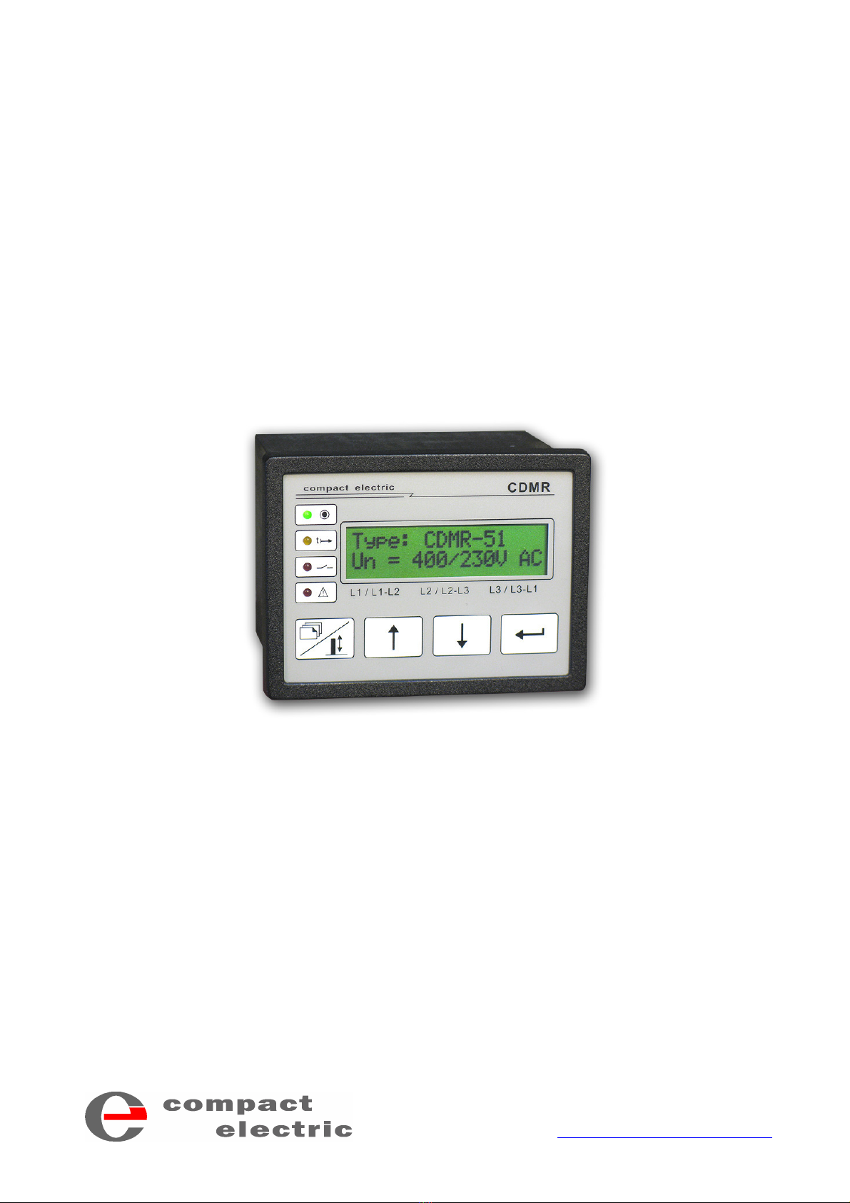
The CDMR-51 is a digital line monitoring relay based on a new generation microcontroller. It provides 13 monitoring
functions listed below with identification symbols.
U< ... undervoltage stage 1 f< ... underfrequency stage 1 PS> ...Phase Shift (Vector surge)
U<< ... undervoltage stage 2 f<< ... underfrequency stage 2 Ba> ... Unbalance (voltage asymmetry)
U> ... overvoltage stage 1 f> ... overfrequency stage 1 SEQ ... Phase Sequence
U>> ... overvoltage stage 2 f>> ... overfrequency stage 2
Configuring the relay
If the relay is configured via the front panel see also fig. 3 and fig.4 (page 9,10) for basic information. If the serial commu-
nication program is used see page 8 for more information.
1. After connection to power supply a standard menue "Line .... " is displayed showing the
line frequency and voltages. Starting from this menue you can step to any menue of the
scheme by first scrolling up or down to the desired main-level menue with the keys and
and then branching with the ENTER key into the chain of detailed-menues. The de-
tailed-menues may again be scrolled up and down by the and keys.
2. First the parameter for 3- or 4-wire mains (main menue "General Settings") shall be
set, because different data sets are used for voltage limits in star-type and delta connec-
tion.
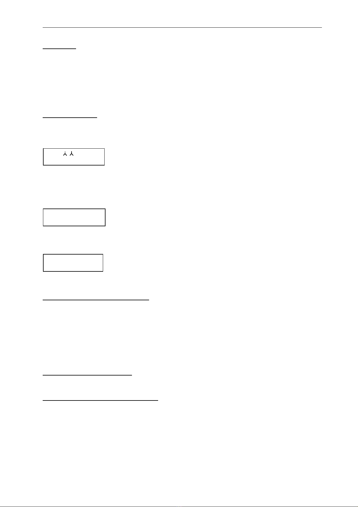
3. Configure the desired monitoring functions: Step to the main menue of the function (ex-
ample U<< on the left side). The identification symbol of the function is always placed in
the right corner of the first displayline (both in the main-level menue and the chain of
detailed-menues). In the second displayline the output relay(s) assigned to the function
are listed: e.g. "K1__4_" means, that both output relays K1 and K4 will be switched to
the alert state in the case of U<<. The assignment can be configured in the detailed-
menue "Output-Relay U<<".
If no output relay is assigned to a monitoring function this function is disabled,
(second displayline = "K_____").
How to change settings see page 6.
Configuring star-type or delta connection
Setting menue: "General Settings \ 3-/4-Wire Mains".
In the star-type configuration the line-to-neutral voltages are monitored and displayed in the main "Line ...." menue. The
line-to-line voltages are also measured, but not used for monitoring. These values can be displayed in the alternative
"Line ....." menue (see fig.3). In delta connection the line-to-line voltages are monitored and displayed in the main "Line
...." menue, the neutral point is reproduced internally. The resulting star voltages can be displayed in the alternative "Line
... " menue. If star-type connection is selected, only the star voltage limits are displayed and changeable, if delta con-
nection is selected, this applies to delta voltages. The upper and lower limits of all voltage monitoring functions are
saved in different data sets. In the PC configuration program both limits are displayed and changeable.
Connection to a single-line system
Connect the single line to inputs L1, L2 and L3 and select star-type connection.
Voltage monitoring U<<<, U<<, U<, U>, U>>
The rms values of the 3 star voltages and 3 delta voltages are measured and refreshed in 20ms intervals at 50Hz .
Details for monitoring see above. Voltage monitoring is single phase sensitive, any undervoltage function is energized, if
at least one voltage is below the low-limit value, any overvoltage function is energized, if at least one voltage is above the
upper-limit value. Undervoltage energizing may be inhibited by the external blocking input "B" (see page 7).
If the line voltage is used as supply voltage, it is strongly recommended to configure the U<< and U< functions with
negated output relays, because otherwise no tripping is possible in the case of line voltage failure.
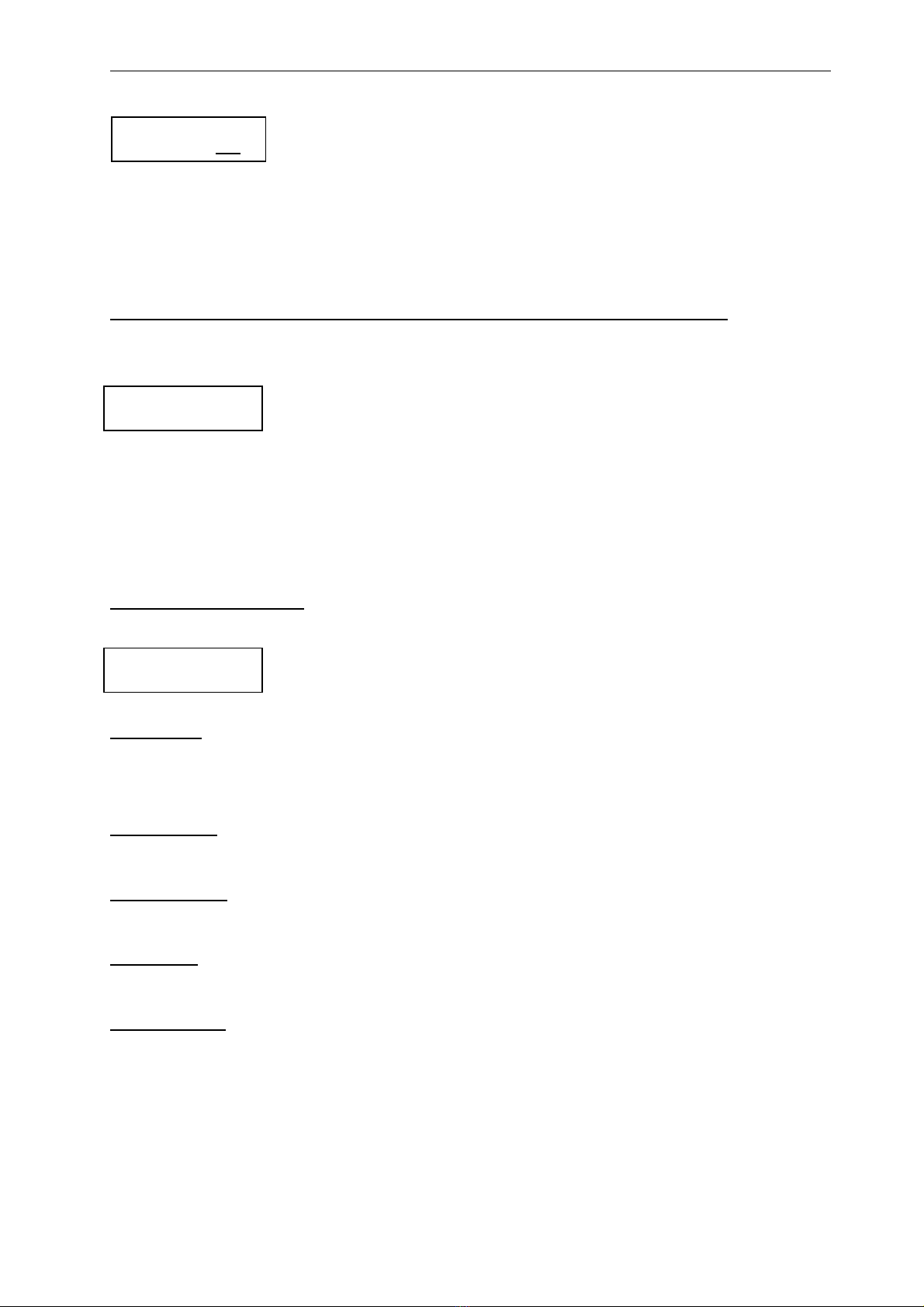
Line / 50.00Hz
230V 230V 230
V
Undervoltage U<<
Stage2 K1__4_ <-
Unterspanng. U<
Stufe1 K_____<-

Line Monitoring Relay CDMR-51 / User Manual Page 6
CDMR51e_man_A11.doc
Attention: Operating in parallel with system requires undervoltage limits >= 70% Un (rated voltage) of at least
one undervoltage function, because frequency and phase shift functions are inhibited,
if all 3 voltages drop below 70% of Un.
Unbalance Ba> (Voltage Asymmetry )
The unbalance function is energized, if any difference between the 3 line voltages exceed the limit value. Depending on
star-type or delta connection selected, the corresponding voltages are monitored. Energizing is independent of absolut
voltage values and also active in the case of single or double total voltage failure. Blocking by the external input B is
possible (see chapter on page 7)
Frequency monitoring f<<, f<, f>, f>>
Frequency monitoring comprises all 3 lines but requires at least one line voltage >= 70% Un to be enabled. Energizing
is inhibited, if all line voltages drop below 70% Un. These functions may also be inhibited by the external blocking
input (see page 7).
Phase Shift PS>
Phase Shift (Vector surge) monitoring is carried out independently in each line. Tripping logic depends on the parameter
value in the menue "Phase Shift .. PS> \ Sensitivity..PS>":
1-phase: Tripping is carried out if the Phase Shift setting value is exceeded in at least in one line (L1 or L2 or L3)
3-phase: Tripping is only carried out if the Phase Shift setting value is exceeded in all three lines (L1 and L2 and L3)
simultaneously
Phase Shift energizing of a single line is inhibited, if the voltage of this line drops below 70% Un. Energizing is
further inhibited:
- for the selected "BlockingTime" after power-on (supply voltage)
- for the selected "BlockingTime" after rising of a line voltage (from failure) above 70% Un.
- by the external blocking input (After release of the blocking input, the "BlockingTime" is started and the function is still
inhibited until this time interval has passed).
The length of the PS> tripping signal is selectable in the menue "Phase Shift..PS> \ Pulsewidth... PS>"
Phase sequence SEQ
The phase sequence (L1-L2-L3) is checked once on the rising of all 3 line voltages above 60%Un or in the case of
power-on of the supply voltage. A wrong phase sequence forces the assigned relay(s) to be permanently in the alert
state. The display shows the message: "PHASE SEQUENCE L1-L2-L3 fault!"
Change of setting values
Refer to fig.3 and fig.4 for additional information.
1. Starting from the standard line measuring values menue step through the main-menue
level with the keys or to the main menue of the desired function (e.g. U<).
2. Branch to the detailed-menue chain with the "ENTER" key and step up / down with the
and keys to the desired parameter menue. In the lower display line the setting range of the
parameter is put in brackets, the parameter value is displayed on the right.
3. Press the "M/V" key (switches keys from Menue scrolling to Value changing).
Now there may be two situations:
Case a) no security code is selected (Code = 000): A "release menue" (see left drawing) is
displayed, "xxx" is a self-incremented change-access counter. Confirm the change-access re-
lease with the ENTER key. (If you entered this menue inadvertently you may escape from the
menue with orkey).
Case b ) Enter the security code: first the leftmost number flashes, set the correct value with
the orkeys, press ENTER, now the mid-number flashed, proceed as just before, press
ENTER, now the rightmost number flashes, set the correct value and terminate with ENTER.
Undervoltage U<
Stage1 K_2___<-
Trip Voltage U<
[ 23–300] 210V
Lock-out Nr.xxx
release? yes<-
Enter Security-
Code....... 000

Line Monitoring Relay CDMR-51 / User Manual Page 7
CDMR51e_man_A11.doc
4. Now the previous parameter menue is displayed again with flashing parameter value. This
value may be altered with the orkeys (keeping a key pressed starts an auto-increment /
auto-decrement function). Press the ENTER key to store and activate the new setting value.
The display returns to static. (If the changes shall be cancelled, press "M/V" key instead of
ENTER and the previous setting value will be restored).
There are 3 ways to continue:
- by the “ENTER” key or key to the next menue,
- by the key to the previous menue
- or by the keys pressed simultaneously branch to the line value menue (= “menue-reset”).
Assignment of output relays to individual monitoring functions and negation of output relays
Select the "Output-Relay nnn" menue in the detail-menue chain of the desired monitoring function (proceed as described
in step 1-3 above). The menues look like this:
In the left example the monitoring function U<< is assigned to relays k1 and K4. The lower
case character of k1 indicates, that this relay is negated. It is energized in the normal state
and released in the tripped state. The "--" characters mark the positions of the (not as-
signed) relays K2,K3 and K5.
4. After execution of step 3 the characters "k1" are flashing. With the keys the assignment can be set or cancelled.
(cancelled = "--").
5. Press ENTER to save the assignment for output relay k1 and move flashing to the position of K2. Select assignment
of K2 and press ENTER. Proceed in this way up to K5.
6. Then to step out of the menue press any key except the M/V key, the M/V key restarts the procedure from step 4.
Negation of K1 ...K5 Function
Select the menue "Special Settings \ Negated Relays":
The configuration procedure is equivalent to step 4 - 6 above. A lower case character indi-
cates negated operation, the “--“ characters indicates normal operation. In the change-mode
the characters are consecutively flashing and may be toggled by keys.
Lock-out Time (only for 230/400 V Relays-Type)
In case of line fault the generating plant will be reconnected once the line operates for a certain period of time within the
permissible limits for reconnection. This time can be preset by „Lock-out Time“
The Lock-out time is effective also in case of power supply failure. The setting range of the „Lock-out Time“ is between 0
and 990 seconds.
Lock-out Relays (only for 230/400 V Relays-Type)
The preset “Lock-out Time” is effective only if at least one output relay is set as “Lock-out Relay”
By default the relays K1 and K2 are parameterized with negated function as “Lock-out Relays”.
10Min Mean value (only for 230/400 V Relays-Type)
For the monitoring of the overvoltage U> limit 10 minutes mean values of single phases are used.
If this parameter is off, the current values are taken for the monitoring of the overvoltage U> limit.
KU Detection (only for 230/400 V Relays-Type)
In case of tripping of the CDMR-51 and the mains is in order within 3 seconds, then the generating plant is reconnected
within 5 seconds. (Instead of the time, which is preset as Lock-out Time.). If this parameter is off, the KU detection is inactive.
fU Connect-Logic (only for 230/400 V Relays-Type)
The generating plant is connected only if the mains voltage ranges between Connection Voltage Uz > / Uz < and if the
mains frequency is lower than the first Over-frequency value ( f>). After connection these tripping values are inactive and
the voltage will only be monitored with the values U< / U>> and the frequencies will monitored with the values f< / f>>.
Connection Voltage Uz > / Uz <
Uz > = Max. Connection Voltage (switching point = Reset value of U>>)
d.h. Uz> = [U>> - Hysteresis] for example: 265 V - 12 V = 253 V
Uz < = Min. Connection Voltage (switching point = Reset value of U<)
d.h. Uz< = [U< + Hysteresis] for example: 184 V + 23 V = 207 V
Trip Voltage U<
[ 23–300] 210V
Output-Relay U<<
k1 -- -- K4 --
Negated Relays
= k1 -- -- -- --

Line Monitoring Relay CDMR-51 / User Manual Page 8
CDMR51e_man_A11.doc
If the Parameter „fU Connect-Logic“ is turned off, the settings U> / U< und f> are taken as tripping values also after the
connection.
100%
50,00 Hz
110% (U >)
z
50,05 Hz (f >)
z
90% (U <)
z
80% (U<)
47,5 Hz (f<)
112% (U>)
115% (U>>)
Functional diagram for activated setting of:
- Lock-out Time
- Lock-out Relays
- 10 Min. Mean value
- fU Connect-Logic
51,50 Hz (f>>)
10 Min.
Mean val.
10 Min.
Mean val.
Lock-out
Time
Lock-out
Time
Lock-out
Time
Lock-out
Time
Lock-out
Time
t
a
t
a
t
a
t
a
K1 K2,
K1 K2,
U
f
t
t
Voltage curve
Frequency curve
Legende: U = Connection Voltage
z
fz= Connection Frequency
t = Tripping Time
, = Negated Output Relays
a
K1 K2
FIG.3 FUNCTIONAL DIAGRAM
Security Code / Change-Access Release
To prevent unauthorized changing of setting values via the front panel, a three-digit security code can be stored in the
data memory. It has to be entered to get permission to alter parameter values.
If the security code is 000, the security sequence is not active and is replaced by a simple menue with a self-
incremented change-access counter (see step 3 above). The value of this counter may be used as indication of any
access to the change mode. The security code can be modified in the menue "Special Settings \ Security code". Subse-
quent changing of the code is possible, but also in this case the active code has to be entered to get the permission for
changing.
Supply Voltage
Usually a buffered DC voltage is used as supply voltage of the relay. For special applications any line voltage from 70V
AC to 300V AC /45Hz-65Hz (absolute minimum and maximum voltage) may be used, but attention has to be payed to
the fact, that all output relays are de-energized in case of total line failure and complete correct recording of the tripping
values in the event buffer cannot be assured.
Event Recording Buffer
Any initial tripping event is recorded in a non-volatile buffer with a data set containing tripping function and currently
measured line values at the tripping instant. This information is displayed in the menue "Event Monitor / Last Trip" and is
only available for the last trip. Related to each tripping function the following measurement values are stored:
U<<, U<, U>, U>>: star voltages or delta voltages,

Line Monitoring Relay CDMR-51 / User Manual Page 9
CDMR51e_man_A11.doc
Ba>: unbalance voltage
f<<, f<, f>, f>>: line frequency
PS>: phase shift values in L1, L2 and L3
Note: If the line voltage is used as supply voltage a correct storage of these data cannot be guaranteed in case of total
line drop out.
There are three more menues in the "Event Monitor" chain, showing currently starting functions, currently tripping functions and
currently energized output relays.
External blocking input "B"
Depending on the parameter value stored in the menue "Special Settings \Ext. Blocking U,f" the external input affects the
CDMR-51 operation as follows:
„Ext.Blocking U,f“ Effect
0 ............ Blocking only the Phase Shift PS>
1 ............ Blocking effect to PS>, U<<, U<, f<<, f<, f>, f>> and Ba>.
If blocking is released and a line fault present, tripping is performed after the time delay
programmed for the corresponding monitoring function.
2 ............ Blocking of all monitoring functions. If blocking is released and a line fault present, tripping is
performed after the time delay programmed for the corresponding monitoring function.
.
Self-monitoring
The relay has a self-monitoring program for error detection in the data memory (checksum er-
rors) which in the error case displays a message "DATA ERROR Parameter No. xxx". If the pa-
rameter "Selfmonitor.->K5" is set, the output relay K5 is changed to the alert state.
The number "xxx" in the display corresponds to the parameter number in the left column of table 1. If two numbers are
listed for one parameter, the first number refers to the corresponding star-type voltage, the second one to the corre-
sponding delta voltage. In the case of a checksum error of this kind, elimination may be successful by entering the pa-
rameter value once again (also in the case the displayed parameter value is correct).
Parameter numbers 91 to 97 are used for internal scaling. In this case the unit has to be returned to the factory.
The K5 control circuit is desiged to perform a watchdog function. If the K5 is configured as negated, it will be de-
energized not only in case of a data error or power supply failure, but also in case of a controller hardware failure.
Additional or alternative to self-monitoring the K5 can be assigned to any other monitoring function without restriction.
DATA ERROR
Parameter No:xxx

Line Monitoring Relay CDMR-51 / User Manual Page 10
CDMR51e_man_A11.doc
Serial Interface:
The serial interface provides an easy tool to configure the relay via Laptop or PC and to save parameter settings on disc
or make a hardcopy for documentation. A special adapter to a standard 9 pin SubD COM connector is available.
The communication-program is available for free on www.compactelectric.at.
FIG. 4 PC COMMUNICATION PROGRAM MENUE
Configuring the relay by PC :
1. First a download of parameter settings is required:
a) from the connected relay (PC-menue "Senden/Empfangen" / "Parameter empfangen")
or b) from a file „Datei“ / „öffnen“ (File-Extender: ".par")
2. Enter the parameter setting values and send to the relay ( “Senden/Empfangen” / “Parameter senden“)
Data transfer does not disturb relay operation with one exception: If the parameter "star-type / delta mains" is changed a
short undervoltage tripping may occur.
Documentation of parameter settings:
A complete parameter setting can be stored on disc (File-extender .par) using the
pull-down menue „Datei” / “Speichern“. For hardcopies select the pull-down menue „Datei” / “Drucken“.

Line Monitoring Relay CDMR-51 / User Manual Page 11
CDMR51e_man_A11.doc
Displaying measuring values on the screen:
Select the menue "Information”. The window shows the relay ID, the line values and the state of K1 .. K5. All values are
refreshed in 1s interval.
Installation:
Operating System ... : Windows XP, Windows 7 and Vista
Connection............... : COM (9pin. SubD connector) or COM adapter for USB
COM Interface ......... : COM1 ..COM4 selectable (menue “Optionen”).

Line Monitoring Relay CDMR-51 / User Manual Page 12
CDMR51e_man_A11.doc
Fig. 5.: CDMR-51 MENUE DIAGRAM
Lin e Y /Y 5 0.00Hz
23 0V 2 30V 2 30 V
Und er volta ge U <<
Stag e 2 K__ __ <-
Und er volta ge U<
Stag e 1 K12 __ < -
Ove rvo ltag e U >
Stag e 1 K 12 __ _ < -
Ove rvo ltag e U >>
Stag e 2 K 12 __ _ < -
Und erfreq u . .. f<<
Stag e 2 K __ __ _ < -
Und erfreq u .. . f<
Stag e 1 K 12 __ _ < -
Ove rf re qu ... f>
Stag e 1 K 12 __ _ < -
Overfrequ ... f>>
Stag e 2 K__ __ < -
Phase Shif t .. . PS>
... .... ..... .K_ __ __ <-
Unbalance Ba>
K_____ <-
Ph ase Se qu . S EQ
... .... ..... K__ __ _ <-
Special
Settings <-
Relay
Informations
Event Mo nitor
... .... ..... .... ..... . < -
Hysteresis ... U<<
[ 0- 50] 5V
Setting Val . U<<
[ 2 3- 30 0] 16 2V
t-Auslösung .U<<
[0 - 60 0] 0.1 0s
Return Delay U<<
[0 - 60 0] 0 .1 0s
Output-Relay U<<
-- -- -- -- --
Lin e Y / 50.00 Hz
40 0V 4 00V 4 00 V
MAIN MENUES DETAIL-MENUES
Pulsewidth .... PS>
[ 1- 20] 1s
Setting Val. PS>
[ 1 -30] 8°
Sensitivity PS>
[ 0 / 3] 3-phase
Blocking-Time PS>
[ 1 - 20] 5s
Output-Relay PS>
-- -- -- -- --
Hysteresis ... Ba>
[ 0- 50] 5V
Setting Val. Ba>
[ 2 -120] 45V
Trip De lay ....B a>
[0 - 60 0] 0 .1 0s
Return Delay Ba>
[0 - 60 0] 0.1 0s
Output-Relay Ba>
-- -- -- -- --
Output-Relay SEQ
-- -- -- -- --
Last Trip : U>>
26 5V 2 60V 288 V
En er gizi ng no w :
U<
Tripp i ng no w:
U<
Pi ck e d-up Rel ays
k1 k2 -- -- --
U> 10 Mi n Me an val
[ 0 - 1] .... ON
La ng ua ge Se tti ng :
[g erm/ engl] . ... 1
3- / 4- Wire Ma in s:
[ , ] =
Ty p e: C DM R -5 1
Un = 400/230V AC
Lo ck-out Ti me:
[ 0 - 990] ... 3 0s
Security Cod e:
[ 0 - 999] . ...0 00
Lo ck-out Rel ais:
= k1 k2 -- -- --
LCD-Contrast:
[ 0 - 20]. ... 1 0
K U De tect io n:
[ 0 - 1] .... ON
[f U Co nn ect- L ogi c:
[ 0 - 1] .... On
E xt. B lo cking U, f
[ 0 - 2] .. .. 0
Self-monit. ->K5:
[ 0 - 1] .... O N
Negated Relays:
k1 k2 -- -- --
S er ial- No : 0 00 000
S oft w . J1 30 9- 07
Deta ile d- m enu e chain eq ui vale nt t o U< <
Deta ile d- m enu e chain eq ui vale nt t o f<<
Hysteresis ... f<<
[ 0- 5] 0.00Hz
Setting Val. f<<
[ 4 5 -6 5] 47 .00 H z
Trip Delay ... f<<
[0.06 - 60] 0.20s
Retu rn Dela y . f <<
[0.06 - 60] 0.10s
Output-Relay f<<
-- -- -- -- --
A
A
Retu rn to th is me nu e f ro m
an y m en ue by p ressing
the keys and simulta neously
Line measuring values:
Standard display after power-on

Line Monitoring Relay CDMR-51 / User Manual Page 13
CDMR51e_man_A11.doc
1) Standard-Display:
LINE MEASURING VALUES
2) MAIN MENUE (Example for undervoltage, stage 2, U<<):
Menue ID.
If any tripping is active
the tripping function-
symbol is displayed
alternately
Mains
configuration
= star-type
= delta
measuring
values
= star voltage
= delta voltage
Okay-LED (green)
indicates fault-free line system
Any energizing active
(Trip delay in progress)
Any tripping active
LED=static if blocking input is set
flashing: on device fault
"M/V" key:
switching of voltage display
between and voltages
Scroll up and down
main menues
Scroll up and down
main menues
Fig. 6: FRONT- DISPLAY AND KEYPAD
Branches to the detailed menue
chain of the U<< function
"K12___" indicates which output relay(s)
is(are) programmed to be affected by the U<< tripping
function. In this example K1 and K2.
Symbol of the tripping function displayed
3) DETAILED MENUE (Example for undervoltage, stage 2, U<<, trip voltage setpoint):
a) normal mode: menue scrolling
b) when value-change mode is selected
(flashing setpoint value) :
increment / decrement setpoint value
a) normal mode: step to next detail menue
b) value-change mode (flashing setpoint value):
save flashing value in parameter memory
Symbol of the tripping
function displayed
Setting value
Setting range
"M/V" Key:
Toggles the action mode of
up / down keys between
" enue scrolling" and
" increment / decrement
of setpoint
M
V
alue"
If no output relay is displayed (K_____ ), the function
does not affect any relay and therefore is not active at all.
"ENTER" key
"ENTER" key
"M/V" Key
From any menue you can branch to the standard display (see example 1) by simultaneously pressing and keys.
"ENTER" Key

Line Monitoring Relay CDMR-51 / User Manual Page 14
CDMR51e_man_A11.doc
Table 1:
Type: CDMR- 51 Serial-No:
U(rated): ........... V AC
Plant: Cubicle:
Date:
Param
No. *) Funct. Parameter Setting
Range
Factory
Setting
230 / 400 V
Factory
Setting
57 / 100 V
Customers
Setting Value Dim
22, 24 U<< Setting Value [10 - 130%] Un 162 / 285 V 40 / 70 V V
26 U<< Trip Delay [0,04 - 60] s 0,10 s 0,10 s s
27 U<<
Return Delay [0,04 - 60] s 0,10 s 0,10 s s
23, 25 U<< Hysteresis [0 - 20%] Un 5 / 8 V 2 / 2 V V
21 U<<
Output Relay K1 ..K5 -- --
15, 17 U< Setting Value [10 - 130%] Un 184 / 320 V 46 / 80 V V
19 U< Trip Delay [0,04 - 60] s 0,20 s 0,10 s s
20 U<
Return Delay [0,04 - 60] s 0,10 s 0,10 s s
16, 18 U< Hysteresis [0 - 20%] Un 23 / 40 V 2 / 3 V V
14 U<
Output Relay K1 ..K5 K1, K2 --
8, 10 U> Setting Value [10 - 130%] Un 258 / 448 V 64 / 110 V V
12 U> Trip Delay [0,04 - 60] s 0,04 s 0,10 s s
13 U>
Return Delay [0,04 - 60] s 0,10 s 0,10 s s
9, 11 U> Hysteresis [0 - 20%] Un 0 / 0 V 2 / 3 v V
7 U>
Output Relay K1 ..K5 K1, K2 --
1, 3 U>> Setting Value [10 - 130%] Un 265 / 460 V 70 / 120 V V
5 U>> Trip Delay [0,04 - 60] s 0,10 s 0,10 s s
6 U>>
Return Delay [0,04 - 60] s 0,10 s 0,10 s s
2, 4 U>> Hysteresis [0 - 20%] Un 12 / 20 V 2 / 4 V V
0 U>>
Output Relay K1 ..K5 K1, K2 --
50 f<<
Setting Value [45 -65] Hz 47,00 Hz 49,00 Hz Hz
54 f<< Trip Delay [0,06 - 60] s 0,20 s 0,08 s s
55 f<<
Return Delay [0,06 - 60] s 0,10 s 0,12 s s
51 f<< Hysteresis [0 – 5,00] Hz 0,00 Hz 0,05 Hz Hz
49 f<< Output Relay K1 ..K5 -- --
continued on next page

Line Monitoring Relay CDMR-51 / User Manual Page 15
CDMR51e_man_A11.doc
Param
No. *) Funct. Parameter Setting
Range
Factory
Setting
230 / 400 V
Factory
Setting
57 / 100 V
Customers
Setting Value Dim
43 f<
Setting Value [45 -65] Hz 47,50 Hz 49,80 Hz Hz
47 f< Trip Delay [0,06 - 60] s 0,20 s 0,08 s s
48 f<
Return Delay [0,06 - 60] s 0,10 s 0,12 s s
44 f< Hysteresis [0,00 – 5,00] Hz 0,00 Hz 0,05 Hz Hz
42 f<
Output Relay K1 ..K5 K1, K2 --
36 f>
Setting Value [45 -65] Hz 50,05 Hz 51,00 Hz Hz
40 f> Trip Delay [0,06 - 60] s 0,20 s 0,12 s s
41 f>
Return Delay [0,06 - 60] s 0,10 s 0,12 s s
37 f> Hysteresis [0 – 5,00] Hz 0,00 Hz 0,05 Hz Hz
35 f>
Output Relay K1 ..K5 K1, K2 --
29 f>>
Setting Value [45 -65] Hz 51,50 Hz 52,00 Hz Hz
33 f>> Trip Delay [0,06 - 60] s 0,20 s 0,12 s s
34 f>>
Return Delay [0,06 - 60] s 0,10 s 0,12 s s
30 f>> Hysteresis [0 – 5,00] Hz 0,00 Hz 0,05 Hz Hz
28 f>>
Output Relay K1 ..K5 K1, K2 --
57 PS > Setting Value [1- 30] ° 8 ° 8 ° °
58 PS > Sensitivity [0 - 1] 3-phase 3-phase
61 PS > Blocking Time [1 - 20] s 5,00 s 1 s s
62 PS > Pulswidth [1 - 20] s 1,00 s 1 s s
56 PS > Output Relay K1 ..K5 -- --
71, 73 Ba > Setting Value [1 - 50%] Un 45 / 80 V 12 / 20 V V
75 Ba > Trip Delay [0,04 - 60] s 0,10 s 0,1 s s
76 Ba > Return Delay [0,04 - 60] s 0,10 s 0,1 s s
72, 74 Ba > Hysteresis [0 - 20%] Un 5 / 10 V 2 / 2 V V
70 Ba > Output Relay K1 ..K5 -- --
77 SEQ Output Relay K1 ..K5 -- --
79 General: Mains 3- /4-Wire 3-/ 4-Wire 3-/ 4-Wire
78
Negated Relays K1 ..K5 K1, K2 --
64 Lock-out Time 0 – 990 s 30 s -- s
63 Lock out Relays K1 … K5 K1, K2 --
65 U> 10 Min. Mean v. on / off [0/1] on --
66 KU-Detection on / off [0/1] on --
67 fU Connect-Logic on / off [0/1] on --
80 Ext. Blocking 0, 1, 2 0 0
82 Self-Monitor. ->K5 on / off [0/1] on off
98 Security Code [ 0 - 999 ] 000 000
81 LCD Contrast [ 0-20 ] 10 10
87 Language Setting germ/engl [0/1] 0 0
91-97 No user access, see chapter self-monitoring
*) Note: Two numbers in this field refer to star and delta voltage.
Table of contents
Other Compact Electric Relay manuals