COMPANION GB100 User manual

CAST IRON
FRAME
COOKERS
OWNERS MANUAL
Part No. GB100, GB200, GB300
11,770 BTU - 35,315 BTU
Cert. 8383G

2
GENERAL WARNINGS
This appliance shall only be used with a LPG rellable
gas cylinder certied to AS 2469 which has a Type 21
POL tting designed to comply with AS 2473.
IT MAY BE HAZARDOUS TO ATTEMPT TO FIT OTHER
TYPES OF GAS CONTAINERS.
ONLY USE IN WELL-VENTILATED AREAS.
CARBON MONOXIDE HAZARD - USING THIS APPLIANCE
IN AN ENCLOSED SPACE MAY CAUSE DEATH. DO NOT
USE IN CARAVANS, TENTS, MARINE CRAFT, CARS,
MOBILE HOMES OR SIMILAR LOCATIONS.
CAUTION: accessible parts may be very hot. Keep young
children away.
USE OUTDOORS ONLY.
SAFETY INFORMATION
Inspect the appliance regularly for signs of wear, leaks
or incorrect operation. If symptoms such as aring of
the burner, issues with lighting, damages to hoses
or connections or leaks from seals or gas controls
are identied do not attempt to repair, return to your
authorised stockist for service and maintenance.
Do not modify this appliance.
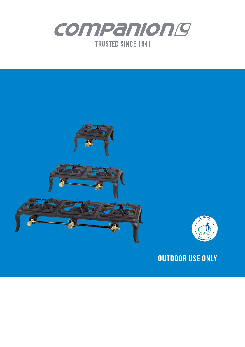
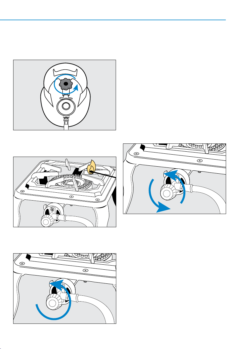
Check that seals between the appliance and the gas
container are in place and in good condition before
connecting the gas container. See gure 1.
Do not use this appliance if it has damaged or worn
seals.
Do not use the appliance if it is leaking, damaged or
does not operate properly.
This appliance is to be operated on a stable, horizontal,
non-ammable surface.
The appliance should be protected from direct drafts
and in a well ventilated place.
Gas orices and burner must be kept clear of dirt and
cobwebs. Flow of combustion and ventilation air through
the perforated portions of the appliance must not be
obstructed.
Any cleaning agent used on the appliance must be of a
non-combustible and non-corrosive nature.
Gas containers shall be changed in a well-ventilated
location, preferably outside, away from people and any
source of ignition, such as naked ames, pilot ame,
electric heaters/equipment.
IMPORTANT: Read these instructions for use carefully. Familiarise yourself with the appliance before
connecting it to its gas container. Keep these instructions for future reference.

3
CAST IRON FRAME COOKERS OWNERS MANUAL
CARBON MONOXIDE HAZARD
Using this appliance in an enclosed space may cause DEATH.
Do not use in caravans, tents, marine craft, cars, mobile homes
or similar locations.
Only use the hose assembly supplied with this appliance
for connection to the cylinder - DO NOT USE ADAPTORS.
Do not use hoses with a length greater than 1.2 m.
Return to your place of purchase for spare parts, service
and repair.
This appliance must only be serviced by an authorised
person.
This appliance must be operated away from any
ammable material or surfaces and materials.
Always operate appliance a minimum of 1 m from
ammable materials, walls and ceiling.
Ensure all packaging is removed prior to use.
Do not operate this appliance before reading the
instruction booklet.
Do not place articles on or against this appliance.
Do not store chemicals or ammable materials, or spray
aerosols near this appliance.
Do not operate in an enclosed area without ventilation.
Do not operate in a boat, caravan or tent.
Figure 1: O-RING seal on the POL regulator.
O-RING

4
UNDERSTANDING YOUR APPLIANCE
REGULATOR AND
1 M HOSE
O-RING
TRIVET
BURNER
AERATION ADJUSTMENT
AERATION ADJUSTMENT
GAS INLET CONNECTION
1/4"GAS INLET CONNECTION
GAS CONTROL
GAS CONTROL
LEGS

5
CAST IRON FRAME COOKERS OWNERS MANUAL
ASSEMBLY
REQUIRED TOOLS
• Phillips head screwdriver
• Adjustable wrench
• Solid and stable assembly area
Step 1. Locate the four legs and fasteners.
Step 2. Attach legs to cooker frame using the bolts,
washers and nuts provided, and secure.
Step 3. Locate gas control.
NOTE: Identify the suitable direction that gas inlet is
required to face prior to assembly.
Step 4. Attach gas control to each burner using screws
and washers provided, and secure.

6
CONNECTION
Your appliance is designed to connect directly on to a
POL gas cylinder using the specially designed LP Gas
hose and regulator supplied with the appliance.
Check that the gas controls are in the OFF position.
See gure 2.
Take the stove connector head of the hose and
attach to the gas inlet on the appliance, tighten
using a spanner. See gure 3.
Attach the other end of the hose to the gas cylinder
and tighten. See gure 4.
Turn the cylinder gas valve on in an anti-clockwise
direction for one full turn and then check the
connections for leaks with Companion Gas Leak
Detection Spray or soapy water. If a leak is detected
turn the cylinder gas valve OFF and re-tighten all
connections, then retest. See gure 5.
Figure 2
Figure 3
Figure 4
Figure 5

7
CAST IRON FRAME COOKERS OWNERS MANUAL
CHECKING FOR GAS LEAKS
Check that all connections are tight and that the gas
cylinder connection has been tightened before you turn
the cylinder gas valve on.
If there is a leak on your appliance (smell of gas)
immediately attempt to turn off the cylinder valve.
Remove the appliance to a well-ventilated location away
from any ignition source.
NEVER check for leaks with a ame or pilot light.
Check for leaks using Companion Gas Leak Detection
Spray or soapy water, coat all connections, if bubbles
appear turn the cylinder gas control off and re-tighten
the connection before re-testing.
SAFE LOCATIONS
This appliance shall only be used in an above ground
open air situation with natural ventilation, without
stagnant areas, where gas leakage and products of
combustion are rapidly dispersed by wind and natural
convection.
Any enclosure in which the appliance is used shall
comply with one of the following:
An enclosure with walls on all sides, but with no
overhead cover (see example 1).
Within a partial enclosure that includes an overhead
cover and no more than two walls (see examples 2 & 3)
Within a partial enclosure that includes an overhead
cover and more than two walls, the following shall apply:
at least 25% of the total wall area is completely open.
30% or more in total of the remaining wall side, back
and front wall areas is open and unrestricted
(see examples 4 & 5).
In the case of balconies, 20% or more of the total wall
area shall remain open and unrestricted.
DIAGRAMMATIC REPRESENTATION OF OUTDOOR AREAS
The following examples are diagrammatic
representations of outdoor areas. Rectangular areas
have been used in these examples - the same principles
apply to any other shaped area.
Example 1
Example 2
Example 3
Example 4
Example 5
Both ends open
Open side at least 25% of total wall area.
30% or more in total of the remaining wall area is open and unrestricted.
Open side at least 25% of total wall area.
30% or more in total of the remaining wall area is open and unrestricted.

8
IMPORTANT INFORMATION FOR USE
During operation all surfaces will be extremely hot and
should not be touched or handled.
Handle with care even after brief use, always pick up
using the handle not the cylinder.
Take care that the primary air intakes, located on the
burner tube of this appliance are not obstructed, or that
air ow is restricted by placing items or other appliances
close to or adjacent to the inlets.
Do not attempt to move or relocate the appliance when
it is operating, extinguish the burner and allow to cool,
disengage the gas cylinder then move the appliance.
This appliance is to be stored in a dry and
well-ventilated location free from direct sunlight.
Do not store when still connected to the cylinder.
Make sure that the cylinder is disconnected and is stored
in a well ventilated area, out of the reach of children,
free from direct sunlight, heat and ignition sources.
If being stored indoors, ensure that the location complies
with the standard AS/NZS 1596.
Never leave appliance unattended when operating.
Do not use a multiple appliances to heat a single utensil.
Only cooking vessels with a minimum diameter of 25 cm
and a maximum diameter of 30 cm are to be used with
this appliance.
Do not use as a space heater.
Use as a cooking appliance only, is not to be used as
heater or modify for any other reason.
Avoid boil over and spills on to burners.
After use, turn the gas cylinder valve off, wait for the
ame to go out, then turn the appliance control valve(s)
off.
Avoid twisting or kinking the exible hose.
To check if gas remains in the cylinder, disconnect from
the appliance and hold the cylinder in a vertical position
then shake from side to side, if there is a sound or feel of
liquid movement inside, the cylinder contains gas.

9
CAST IRON FRAME COOKERS OWNERS MANUAL
LIGHTING BURNER
Step 1. Turn the gas cylinder valve on in
an anti-clockwise direction for one full turn.
Step 2. Take a lit match or gas lighter and position close
to the edge of the burner that is to be ignited.
Step 3. Slowly turn the gas control in an anti-clockwise
direction approximately ¼ of a turn.
Note: If the burner does not ignite, turn the gas control
in the clockwise direction to the “OFF” position and
allow the residual gas to disperse before attempting to
reignite the burner.
Note: Locate the gas cylinder away from your cooker to
ensure it is not subjected to radiant heat.
ADJUSTING THE FLAME
To increase the heat output, turn the gas control
in an anti-clockwise direction. To decrease the heat
output, turn the gas control in a clockwise direction
or to turn off.

10
TURNING THE APPLIANCE OFF
If the appliance is no longer to be used and to reduce the
risk of blocked gas jets caused by excess gas being left
in the hose, all remaining gas must be expelled from the
hose assembly.
With the ame still operating, turn the valve on the
gas cylinder in a clockwise direction until it is “OFF”.
Allow the ame to burn down then extinguish once all
remaining gas in the hose has been used. See gure 6.
Turn the gas controls on the appliance to the “OFF”
position. See gure 7.
CARE INSTRUCTIONS
Using warm soapy water with a mild detergent, wipe
down all surfaces and areas of the appliance, taking
care not to allow water to enter the burner outlets or
aeration holes located in the burner tube.
Do not submerge the appliance in a sink or bowl.
Do not use abrasive cleaners or bleach.
MAINTENANCE AND SERVICE
During operation if it is noted that the burner ame is
unstable, is changing colour from blue to yellow or has a
distinct smell it is important that you take the appliance
to your local authorised gas appliance repairer for
inspection.
Periodically check the gas control is tight and has no
leaks, follow the testing for leaks procedure. Check the
gas hose and regulator for any signs of wear, cuts or
fraying, if identied replace immediately with a Gas
Certied replacement hose and/ or regulator.
For further information or assistance please contact
customer service.
A selection of spare parts and components are available
for your appliance to ensure years of operation.
For more information in Australia call 1300 555 197 or
email: service@companionbrands.com.au
For more information in New Zealand call 09 525 6667
or email: service@companionbrands.com.au
Figure 6
Figure 7

11
CAST IRON FRAME COOKERS OWNERS MANUAL
SPECIFICATIONS
Part no. GB100
Model no. Cast Iron Frame Single Cooker
Gas type Propane
Gas jet size 1.10mm
Gas consumption
12.42Mj/hr - 246g/hr
BTU output (total) 11,770
Inlet pressure
2.75 kPa
Dimensions 245L x 265W x 128H mm
Weight 3.4 kg (excl. hose and regulator)
Certificate no.
AGA 8383 G
SPECIFICATIONS
Part no. GB200
Model no. Cast Iron Frame Double Cooker
Gas type Propane
Gas jet size 1.10mm
Gas consumption
24.84Mj/hr - 495g/hr
BTU output (total) 23,340
Inlet pressure
2.75 kPa
Dimensions 488L x 265W x 128H mm
Weight 6.0 kg (excl. hose and regulator)
Certificate no.
AGA 8383 G
SPECIFICATIONS
Part no. GB300
Model no. Cast Iron Frame Triple Cooker
Gas type Propane
Gas jet size 1.10mm
Gas consumption
37.26Mj/hr - 742g/hr
BTU output (total) 35,315
Inlet pressure
2.75 kPa
Dimensions 735L x 265W x 128H mm
Weight 9.0 kg (excl. hose and regulator)
Certificate no.
AGA 8383 G

Distributed by:
Adventure Trading Australia Pty Ltd
www.companionleisure.com.au
Distibuted in New Zealand by:
Gladiator Sports Ltd
This manual suits for next models
2
Table of contents
Other COMPANION Grill manuals