CompuPro 816 Series User manual

C O M PU PR O :/16 C O M PU TER S
SER W C E M A N U A L
SB X C L V IO
P re pa re d by :
X erox C orporation
X e rox Service B uslness
Service E ducation & C ustom er Supporl
:200 B rookriver D rive
D allas, T exas 752 *7
SE P T E M B ER 19:3

CO M PU PRO 1. G EN ER A L D A T A
P R ELIM IN A R Y
C H A PT ER 1 G EN ERA L D A TA
C O M PU PR O C O M PU T ER S SER V IC E M A N U A L
1-1

1. G EN ERA L D A T A CO M PU PRO
PR ELIM IN A R Y
1.1 H O W TO U SE TH IS SERV IC E M A N U A L
Thls servlce m anual provld es Info rm atlon necessary fo r m alntenance of the Com pupro* 8 16
Co m pulers.
1.1.1 M A N U A L C O N T EN T
The m anualls d ivlded Inlo elg ht chapters Content o fchapters ls descrlbed belo w
C ha pter 1 G en eral D ata
Thls cha pler provld es lnform atlon o r Instrucllons fo r m anual usage, speclflcatlo ns, too ls and
supplles Iists,and generalprocedu res
Chapter 2. Installatlo n
Thls chapter provldes procedures fo r Installatlo n eq ulp m ent by a Servlce Representatlve
C hap ter 3 Repa lr D ata
Thls chapter provldes proced ures for rem oval,replacem ent,and adluslm ent of parts Each pro-
cedure refersto related partsIlst(PL)In Chapter4
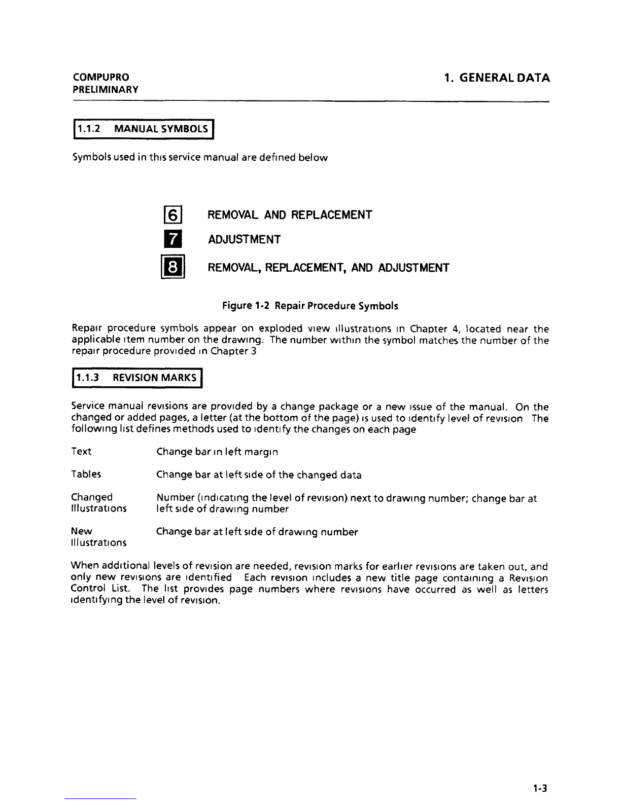
C hapler 4 Parts Identlflcatlo n
Thls chapter provldes exploded vlew Illuslratlons of parts (and parts conflguratlon) and a
m atchlng 11st of parts descrlptlons. The parts Iisl refers to the related repalr procedures In
Chapter3. Sym bols used o n parts Illuslratlonsare defined in Sectlo n 1 1 2.
Chapter5 Prlnt/Dlsplay Q uallly
T hls chapte rls pro vld ed o nly ln ap p llcab le m an uais.
C ha pter 6 T ro u b lesho otln g
Thls chapler provldes Com pupro 816 Com puters troubleshootlng Introd uctlon and explanatlons,
Level 1 C h ecko ut,Level2 CheEk C harts,and pow erd lstrlb ullo n BSD S
Com pu pro* Is a reg lstered tradem ark of Com p upro D lvlslon,G od bo ut Eleclronlcs
1-2 '

CO M PUPRO 1. G EN ERA L D A TA
P R ELIM IN A R Y
1.1.2 M A N U A L SY M BO LS
Sym bols used in thls service m anualare deflned below
6 REMOVAL AND REPLACEMENT
A DJUST M E NT
; R EM OVA L, REPLACEM E NT, AND A DJUST M ENT
Fig ure 1-2 RepairProted ure Sym bo ls
Repalr proced ure sym bo ls ap pear on explod ed vlew Illuslrallo ns ln C hapter 4, localed near the
applicable Item num bero n the d raw lng . The num berw llhln the sym bo lm atches the num ber of the
repalrproced ure pro vlded ln Chapter 3
1.1.3 R EV ISIO N M A RK S
service m anualrevlsions are provlded by a change package or a new Issue of the m anual
. O n the
changed oradded pages,a letter(atthe botlom ofthe page)isused to Identlfy Ievelofrevlslon The
fo llow lng 11st defines m ethods used to Identlfy the changeson each page
Te xl C ha ng e ba r In Ieft m a rgln
Tab les C hange b ar at Ieft sld e of1he cha nged d ata
Changed Num ber(lndlcatlng 1he Ievelofrevlslon)nexlto draw lng num ber;change barat
Illustratlons Ief'tslde ofd raw lng num ber
N ew C ha ng e ba r at Ieft sld e of d raw lng n u m ber
Illustratlo ns
W hen ad dltio nallevels of revlsion are needed,revlslo n m arks fo r earller revlslons are taken oul, and
only new revlslons are Identlfied Each revlslon Includes a new litle page co ntalnlng a Revlslon
Control List. The Ilsl provld es page num bers w here revlslo ns have occurred as w ell as Ietters
ldentlfylng the Ievelof revlslo n .
1-3

1. G EN ERA L D A TA CO M PU PRO
P R ELIM IN A R Y
1.2 SPECIFIG TIO N S
1.2.1 CO N FIG U RA TIO N S
Tab le 1-1 Com p upro C om pulers
C onfig uratio ns
H ardw are
816/A 816/B 816/C 816/D System 68K
Req uired H ardw are
D eskto p Enclosure 2 X X X X X
Flo p py D lsk Enclo su re X X X X X
D lsk 1 PW A X X X X X
CP U 808 5/88 PW A X X X
C P U 808 6/87 PW A X
C P U 68 K PW A X
Syste m Su ppo rt 1 PW A X X X X X
Interfacer4 PW A X X X
Inlerfacer 3 X Note 2 X Note 3 X Note 3
M /D rive/H PW A X X
M em o ry SizeNo'e 1 128 K 256K 384 K 512K 256 K
N ote 1 : Syslem m em o ry ls o bta lned by uslng RA M 16,RA M 17,o r RA M 2 1 PW A S
Note 2: Inlerfacer3 PW A w lth 5 serlalports(notfully populated)
N ote 3: Interfacer3 PW A w lth 8 serlalports(ful6y populated).
1.4 -

O M PUPRO 1. G EN ER A L D A T A
PR ELIM IN A R Y
1.2.2 ELECTRICA L SPEC IFICA TIO N S
Clrcult cond uclors and ground conduclors m ust be Installed In accordance w lth Iocal eleclrical
req ulrem enls. A standard 15A , z-pole, 3-w lre grounded duplex receptacle Is req ulred for proper
m achlne operatlo n.
A C pow er Is obtajned from a grounded w alloutlet. V o ltaqes requlred at the w alloutlet are 103 to
127 VA C Iine to neutral,0 to 3 V A C neutralto g round ,at 60 H z
1-5

CO M PUPRO 2. IN STA LLA T IO N
P R ELIM IN A R Y
C HA PT ER 2 IN STA LLA T IO N
C O M PU PR O C O M PU T ER S SER V IC E M A N U A L
2-1

2. IN STA LLA T IO N CO M PU PRO
PR ELIM IN A R Y
2.1 PR ELIM IN A RY C H EC K S
1 M EA SUREA N D V ERIFY V O LTA G EA T W A LL RECEPTA CLE (FIG U RE 2-1)
C A U T IO N
If any of the voltage m easurem ents is not as spetified below ,the tause m ust be torrected. lnfo rm
the tusto m erthat the eq uipm enl m usl not be to nneu ed to the w allreteptatle.and that a Iitensed
eled rician m usl co rred the w iring . D o not1ry to m ake the co rred io n. If the im pro perto nd itio n has
no1 been to rred ed befo re the next call. provide a w ritten repo rt to yo ur m anag er abo ut the
im pro per w iring .
a M ove m elerRA N G E sw ltch to 150 V A C scale
b. M easure voltage betw een A C hot(A CH)and neutral(A CN)
c V erlfy that m eterread lng ls betw een 103 V A C and 127 V A C.
d. M easure voltage betw een A CH and ground (GND)
e. Verlfy that m eterread ing Is betw een 103 V A C and 127 V A C.
f. M easure vo ltage betw een G N D and A C N .
g. V erlfy that m eterreadlng Islessthan 3 V A C.
ACN (LO NGER ACH (SHO RTER
SLO T) NEUTRA L SLOT) H0 T
II
*
G ND (H O LE)
Figure 2-1 W allReceptatle )
2-2

CO M PUPRO 2. IN STA LLA T IO N
PR ELIM IN A R Y
2.2 C O M PU PRO 816 C O M PU T ERS IN STA LLA TIO N
1 REM O V E T H E D ESKTO P EN C LO SU RE 2 FRO M SH IPIN G CA RTO N A N D C H ECK FO R DA M A G E
a. O pen shlpping carton carefully to preserve packlng m aterlals and slore fo r posslble
future use
b Rem ove any accessorles(m anuals,cables)packed w lth unlt
c. Rem o ve D eskto p Enclosure 2 fro m carton and p lace o n a desk o rtable
d C hetk unlt fo r dam age.
2. REM O V E FLO PPY D ISK EN C LO SU RE FRO M SH IPPIN G C A RTO N A N D C H EC K FO R D A M A G E
a. O pen shlpplng carto n carefully to preserve patklng m aterlals and sto re fo r posslble
future use.
b Rem ove any accessorles(m anuals,cables)packed w lth unlt
c. Rem ove Flo ppy D lsk Entlosure from carton and place nexl to the D esktop Enclosure 2.
d . C heck u nlt fo r dam age
3 CO N N ECT FLO PPY D ISK EN C LO SU RE TO D ESK TO P EN C LO SU R E 2.
a Lo cate the 50 pin flal rlbbo n cab le
b. Connect o ne end of the cable lo 1he D ISK con necto r on 1he rear o f the D esktop
Enclosu re 2
c. C on necl th e o lh er end to th e D ISK co n neclor o n th e rearof th e Flo p py D lsk En clo su re
4. CO N N ECT SY ST EM CO N SO LE T ERM IN A L TO D ESK TO P EN C LO SU RE 2
a. C on nect the Term lnalto TERM IN A L 0 con neclo r al rea rof D eskto p Enclo su re 2
5. IF A PPLICA B LE,CO N N ECT T H E R EM A IN IN G T ERM IN A LS
6. REM O V E T H E FLO PPY D ISK EN C LO SU RE A N D D ESK T O P EN C LO SU R E TO P C O V ERS A N D C H EC K
FO R LO O SE CO N N ECTO RS,A ND CO RRECT CO N FIG U RA TIO N (FIG U RES 2-2 TO 2-16)
7. C O N N EG TH E A C PO W ER C O R D S.
8. PER FO RM LEV EL 1 C H ECK O U T TO V ERIFY SY STEM IS W O RK IN G PRO PERLY
2-3

2 . IN STA LLA T IO N CO M PU PRO
8 16/A PR ELIM IN A RY
S T A N D A R D S W IT C H S E T T IN G S
œ 8* 5/% - off Sl on off S2 (m off 53 on
l x x l x l
2 x x 2 2 x
3 x x 3 x 3
x 4 x 4 x 4
x 5 x 5 x 5
x 6 x 6 x 6
7 x x 7 x 7
x 8 x 8 x 8
DT> l -- o ff Sl on off 52 on
1 x x l
x 2 2 x Jœ D r Sett lng s :
x 3 x 3 .74 - Install a Jtr D r
x 4 x 4 Jl6 - Install a juam r
x 5 5 x on BK
x 6 6 x Jl7 - J tm m r AK
x 7 7 x
x 8 8 x
T- 4 --- off S1 on o ff 52 = o ff 53 on
x l l x l x
x 2 2 x 2 x
x 3 x 3 3 x
x 4 x 4 4 x
x 5 5 x x 5
x 6 6 x x 6
x 7 7 x x 7
x 8 x 8 x 8
9 x
10 x
Jtmlm r Sett iœ s :
Jl - No shun t J26 - Jtm m r A-9 and Ce fo r
.12 - Bottrvn installe w ith EN N rallel printer Juhm r A-C
printer / No shunt otherwise and N D for serzal printer.
J3 - 'm p installe w ith Em on JSl , JS ,2 JS3 - Install shtm t ,
inter / No shunt otherwise M orting all 8 lines.Pr
J4 - Bo ttœ ins talle w ith * :21 Js4 - * connK tions
Epson and cen tronics JS5 - ConnK t pins 13- 16 to pin 5
J 5-J25 - Rœ ov e Js6 - Corm K t p in s 9- 12 to pln 6
2-4 Fig ure 2-2 816/A Standa rd Sw itth Setting s

CO M PUPRO 2. IN STA LLA TIO N
P R ELIM IN A RY 8 16/A
- 51- l - o ff Sl on o ff 52 on off 5 3 on
x l l x x l
x 2 2 x x 2
x 3 3 x x 3
4 x 4 x x 4
x 5 x 5 5 x
x 6 x 6 x 6
7 x x 7 7 x
x 8 x 8 x 8
J œ m r Se tt iœ s :
Jl --- Serial m rt connœ tion J3 - Plm an atzxïliary % tte ry12 - In- rt m eight pm d ip cable into this connector
,e unt, leave ehe loe r re wire toward the left.five pins (m the right 48 - Install an eight p in sh unt
s id e o ut . œ av irv the J 13 - Inmo rt a A o rt iY plY ontofirst thrœ w ires shtm te p roœ s 8 and C .
effectively makes a pomninirN junm rs are left unconne ted.3-W re ser ial connect ion . u 16 - Install the *G o 86 * EPRG
o- U es -- * th M ard s 1st 64K 2M 64K
off Sl * off 52 on off 52 on
x l x l x 1
2 x 2 x 2 x
3 x 3 x 3 x
4 x ' 4 x 4 x
5 x 5 x 5 x
6 x 6 x 6 x
7 x 7 x 7 x
8 x 8 x 8 x
9 x 9 x x 9
10 x 10 x 10 x
- o r - * O f -
- - # *---16 S - X -
1st 64K H 64K
off Sl on off Sl on off Sl on
l x l x l x
2 x 2 x 2 x
3 x 3 x 3 x
4 x 4 x 4 x
5 x 5 x 5 x
6 x 6 x 6 x
7 x 7 x 7 x
8 x x 8 8 x
%
Figure 2-3 816/A Standard Sw itch Settings(Continued) 2-5

2. IN STA LG TIO N EO M PU PRO
:16/A PRELIM IN A R Y
D IS K 1 IN T E R FA C ER 4
5G PIN FLO PPY D ISK fa rm m al2)
IN T E R FA C E R 4IN T E R FA C E R 4 C E N T R O N IC S
(a rm m al 1)PA R A L LE L PR IN T ER PO R T
IN T ER F A C E R 4
SY GTEM SU PK R T CO N SO LE (pnno j)
(œ m inalë
. <>S7tm .- + - ,A% e't
Q * 1 A --a.x'.. v + *- ...
.1t.W -
x-''*''tin % * - **. .. . w a < . q
4'-.) -- -...# <* J# -
.% *
- t j '
.
x - - $- QX
. - - A)
>(!t-
v G '
1 . 4
f
>
F 0 R M A K IM U M C O O L IN G L E A V E E M P T Y S L S T S B E T W E E N B 5 * p 5 S .
7,..7.1 u
> k u t .
= -
DISK 1 . . * +
e * *' * *
. - jN v E q gA c E q 4
@ *@ * .
* * :e
.11!----INTERFACER 4 >
.=< v&< .tw< . osr vJ wv - -...%v @ l e. l1. l
+ + . = ''-w . v
,. - ...> z',gtx .,kp eeIpf.ye
.
tt...
..
.
.
.
.
.
.
.
. .
..e . svsmEu suppo:T 1*X **P*
= . r .
R''W W --'*''M % >* b
z Y M @V -' W *
' * . * @ œ . * p . e e e w
o . . v . w * @ . > . #
- . . ,j qL.+ ,*7.- . = ...
p .+
'
e
'
* . . A *;* *
'
*.X @...>.,ee*Cw
'N .
.1 . -... . -.,
2-6 Fig u re 2-4 %16/A C ab le C o nn ed io ns

CO M PUPRO 2. IN STA LM TIO N
PRELIM IN A R Y g16/:
S T A N D A R D S W IT C H S E T T IN G S
œ 8* 5/88 - off Sl on off 52 on off 53 on
l x x l x l
2 x x 2 2 x
3 x x 3 x 3
x 4 x 4 x 4
x 5 x 5 x 5
x 6 x 6 k 6
7 x x 7 x 7
x 8 x 8 x 8
DTM l - o ff sl on o ff S2 on
1 x x 1
x 2 2 x Jm m r Sett iœ s :
x 3 x 3 J4 - Install a jtr m r
x 4 x 4 Jl6 - Install a jtznm r
x 5 5 x * B-C
x 6 6 x Jl7 - J tr o r AK
x 7 7 x
x 8 8 x
- M - o ff sl =
x l
2 x
3 x
4 x -
x 5
6 x
7 x
8 x
J tznm r Se ttiY s :
Jl -- Insert a dtp shtm t , M tm tfY lines l, 2 ard 3 for a- ire ,
Y hnM e kiY . Consult e ual for hardware hxM e kta l .
J2 --- Insert a dip shtm t , shm ttr/ lines 1 , 2 arxl 3 for 3-wire ,
no haM siw kilN . Consult = tn l for harA are hn'W sM kir/ .
Jl5 -- Connect pins 9- 16 to pin 5
J l6 - Connu pins lH to pin 11
J17 - Jm m r te to p pins .
Re aining juv rs left unconnK te .
Fig ure 2-5 8 16/8 Stand ard Sw itth Setting s 2-7

2. IN STA LLA T IO N CO M PU PRO
8 16/B PR ELIM IN A R Y
- 5>e l - off Sl on off S2 on o ff 5 3 on
x l l x x 1
x 2 2 x x 2
x 3 3 x x 3
4 x 4 x x 4
x 5 x 5 5 x
x 6 x 6 x 6
7 x x 7 7 x
x 8 x 8 x 8
J œ m r Se ttiœ s :
Jl -- Serial port connection J3 -- Plug an auxiliary battery
J 2 -- Inse rt an eig ht p in d ip cab le in to th is connec tor :
sbunt , leav ing the lower red w ire toward the left .
five pins on tbe right J8 -- Install an eight ptn shunt
s ide out . Leav ing the J l3 -- InRo rt a mhn rting plug on to
first three v ires shun ted prongs 8 ana C .
effectively makes a pmmntning janpers are left unconnected.
3-w ire sertal connection . ul6 -- Install the *Go 86* EFREM
x:x- 17 .s -
Al.r. n = 1st 64K 9r<1 64< 3rd 64K 4% 64K
o c Sl œ l off 52 œ off :2 œ l o ff 52 on off 52 on
x 1 x l x l x l x l
2 x 2 x 2 x 2 x 2 x
3 x 3 x 3 x 3 x 3 x
4 x 4 x 4 x 4 x 4 x
5 x 5 x 5 x 5 x 5 x
6 x 6 x 6 x 6 x 6 x
7 x 7 x 7 x 7 x 7 x
8 x 8 x 8 x x 8 x 8
9 x 9 x x 9 9 x x 9
10 x 10 x 10 x 10 x 10 x
. o r .. -- o r -
ou 16 's .- *- M 21 's -
lst 64K 2M 64K 3rd 64K 4% 64K lst 128K 7M 128K
off sl on o ff sl on off sl on off Sl on o ff Sl on off Sl on
l x l x l x l x l x 1 x
2 x 2 x 2 x 2 x 2 x 2 x
3 x 3 x 3 x 3 x 3 x 3 x
4 x 4 x 4 x 4 x 4 x 4 x
5 x 5 x 5 x 5 x 5 x 5 x
6 x 6 x 6 x 6 x 6 x 6 x
7 x 7 x x 7 x 7 7 x x 7
8 x x 8 8 x x 8 8 x 8 x
2-8 Figure 2-6 816/8 Standard Sw itth Settings (Continued)

EO M PUPRO 2. IN STA LLA T IO N
PR ELIM IN A RY g 16/:
N O T E T H E S Y S T E M S U PP O R T 1 S Y S T EM C O N S O LE C A B L E (term lnal 0) IS N O T
S H O W N IN P H O T O 8 E C A U S E IT IS U N D E R N E A T H T H E O T H E R C A B L E S .
IN T E R FA C E R 3
IN T E R FA CER 3 lprllm r 11
tlm nter 01 IN T E R FA C ER 3
('erm lx l3)IN T ER FA C ER 3
(term m al 21 o lsx 1 soopjx
IN T E R FA C E R 3 Fl
-o ppv o ls x C A B K E
lo rm jnal 1h
'Y..A,%.st ..- .. u..a.v.-.. . g-*J1- ,u .
K > * e
w e '
? .w qey v,s w +* wt - -
1.e+ +vâ'
wmv yx - w
w , . m ze --'* - V 'e
1
r? .
*%1
. A-
F O R M A X IM U M C O O L IN G L E A V E E M P T Y S L O T S B E T W E E N B O A R D S .
< jm rW < Y'M e
G w - av v w >
-= =
@ * @ u .@ * . * .DISK1 @ @
* - . @ INTERFACERa@ + .
* @ Or ..INTERFACER3 , . jx g E q gA cEq a
ex-w . -. m..$.e ,- xg-;a'ea-vzzo
- sk-xrite .
* 4<A . t.z.-ow *z..+.. @
r,
.- *' ' ' *: p.a-
.w . sv s-rEM su pjx le T 1
ï gr :k 1 ...aF-Ap..a.
* xcx<,a
*.ïww.*:*.3iT.*ù*.qL*.3i-
@ - -...z r '- e- ''*x
Fig u re 2-7 8 16/B C ab le C onneu io ns 2-9

2 . IN STA LLA T IO N co M pu pRo
816/C PR ELIM IN A R Y
CR I 8085/88 - off S1 on off 52 on off S3 on
1 x x 1 K l
2 x x 2 2 x
3 x x 3 x 3
x 4 x 4 x 4
x 5 x 5 K 5
x 6 x G x G
7 x x 7 x 7
x 8 x 8 x 8
n TM l - o ff S l on o ff 52 on
l x x l
x 2 2 x Ju hm r Settings z
x 3 x 3 .74 - - Install a Ju nD r
x 4 x 4 J16 - Install a Jlr m r
x 5 5 x on B-C
x 6 6 x J l7 - - J tm o r AK
x 7 7 x
x 8 8 x
3-8 -- Ju nper Setting s :
Jl -- Insert a d ip shunt , shunting lines 1 ,
o ff Sl on 2 AGd 3 for 3-W lre no hn nd shak ing .
x l Con sult m nn ual fo r ha rd wa re hand sha king .
2 x J2 -- Inmo rt a d ip sh un t , sh un t ing l in es 1 ,
3 x 2 and 3 for 3-w ire , no hana sha kîng .
4 x Consult m anual fo r hardw are h anashak inq .
x 5 J15 -- Connect pins 9-16 to pin 5
6 x Jl6 -- Conn-ct pins l-8 to Pin 11
7 x J 17 -- J umper two to p p in s .
8 x Rom x in ing Ju npe rs left unconnec ted .
!- > l - o ff Sl on o ff 52 on o ff 53 on
x l 1 x x l
x 2 2 x x 2
x 3 3 x x 3
4 x 4 x x 4
x 5 x 5 5 x
x 6 x 6 x 6
7 x x 7 7 x
x 8 x 8 x 8
JtTRlx r Settiœ s :
Jl - Se rial m rt connection
J2 - Insert an eight pin d ip shunt , leav ing the low r fi've pins on the
right side out. Leav iœ t- first thre w ire.s shunte effK tively
m akes a 3-w ire serial connection .
J3 - P1Y œ n aux il iary battery cable into this connecto r, re w ire
toward the left .
J8 - Ins tall œ : e zght pin shun t
Jl3 - Insert a slw rttng pl* tnto prongs 8 and C .
Remainiœ Jtr m rs are left unconnecte .
U16 - Install the *c,o 86 * EPRœ .
2-10 Figure 2-8 816/C Gtandard Sw ituh Settings

CO M PUPRO 2. IN STA LLA T IO N
P R ELIM IN A R Y 816/C
oa- 17 .s
Arz. n a jst 64K 7M 64K 3rd 64K
o ff Sl = o ff 52 on o ff S2 on o ff 52 on
x l x 1 x 1 x l
2 x 2 x 2 x 2 x
3 x 3 x 3 x 3 x
4 x 4 x 4 x 4 A
5 x 5 x 5 x 5 x
6 x 6 x 5 x 6 x
7 x 7 x 7 x 7 x
8 x 8 x 8 x x 8
9 x 9 x x 9 9 x
10 x 10 x 10 x lû x
4% 64K 5% 64K 6% 64K
off 52 on off 52 on o ff 52 on
x l x 1 x l
2 x 2 x 2 x
3 x 3 x 3 x
4 x 4 x 4 x
5 x 5 x 5 x
6 x 6 x 6 x
7 x x 5 x 7
x 8 8 x 8 x
x 9 9 x x 9
10 x 10 x 10 x
- o r -
1st 64K 2% 64K 3rd 64K 4% 64K 5% 64K 6% 64K
o ff Sl G 1 o ff Sl on off sl (x l o ff Sl on o ff Sl on o ff Sl on
l x l x 1 x l x l x l x
2 x 2 x 2 x 2 x 2 x 2 x
3 x 3 x 3 x 3 x 3 x 3 x
4 x 4 x 4 x 4 x 4 x 4 x
5 x 5 x 5 x 5 x 5 x 5 x
6 x 6 x 6 x 6 x x 6 x 6
7 x 7 x x 7 x 7 7 x 7
8 x x 8 8 x x 8 8 x x 8
e O r -
**** 2l 's - lst 128K * * 128K 3rd 128K
o ff S1 * off S1 on o ff Sl on
1 x l x 1 x
2 x 2 x 2 x
3 x 3 x 3 x
4 x 4 x 4 x
5 x 5 x 5 x
6 x 6 x x 6
7 x x 7 7
8 x 8 x 8 x
Fiqure 2-9 816/C Standard Sw itth Settinqs(Continued) 2-11

2. IN STA LLA T IO N CO M PU PRO
816/C PRELIM IN A R Y
N O T E . TH E S Y ST EM S U PPO R T 1 S Y S T E M G O N S O LE G A 8 LE (term lnal 0) IS N O T >
S H O W N IN P H O T O B E C A U S E IT IS U N D E R N EA T H T H E O T H E R C A B LE S
.
IN T ER FA C E R 3*
IN T E R FA C ER 3* (pn - r o )
INTERFACER a (prl- er j) INTERFACER a* INYERFACER 3**
(- m le 2) (term lnaja) te rm 'n*l41
Ix v en FA c E a a o ls. 1 w p$. IN T E R FA C E R z*-
(œ m lnal1) FLO PPY D ISK CA B LE t'Prm m *l51
INTERFACER 3**#
. Av '.'z- < . . ws e (o rmjsajqjW wxwlfvux't .x . arwo,.l
-> 'sw
zzv > 1*
Y rP '% #.. g .
.) a p, .p .yg
> < *. 0.1 o yjajo a .:o ao yof u ..rdi x> - - . .m..,.#- ...w. .e
'v%xzT ooyjp.jm ajx yaa: ayj:gau a w* t* .
= x 4
IXJZ
v> k
@
-!.ï:..: >,
m- )f
A
F 5 R M A X IM U M C O O L IN G L E A V E E M P T : s k o T s s s T w l e N e o A R o $
.
x . :
*- % .y*:.
-a br .v,,x(v:v +A . D I:II 1GR < .W . ...x . ,IN T E R FA C En a . @ . + ' s .
e x.Qw * *
s q 'v v . w
eh ,h- . 'X /
< ''-
' * * @ f+
e w v d:s s
q.'eA xtx- > r ......w. IN T E R FA C E R 3* 4
.>
x - - .-
*z:iiztztiwê -JJ.-.*JJ.= ....*.. - . INTERFACER 3
- . .: .. .= s - .: ..
*'
.ti.k*ëï:ï?13...4. 4e.:L:e..*e..*'..'%..* :b.%'.*.*.s**kr.*K.*.*.*'.*a*.* ,kq
..y 111, . 111
- . -., - . . , - - ..-., . . -u-. sy sr eM su ppo a v :
2-12 F'Ig ure 2-10 816/C C able C o nned io ns

CO M PU PRO 2. IN STA LG T IO N
PR ELIM IN A R Y g 16/D
. nu u y .
o ff Sl on o ff 52 on o ff 53 on o ff 54 on off 55 on
x l x l x l x l x l
x 2 x 2 x 2 x 2 x 2
x 3 x 3 3 x 3 x x 3
x 4 x 4 4 x 4 x x 4
x 5 x 5 x 5 5 x x 5
x 6 x 6 x 6 6 x x 6
x 7 x 7 7 x 7 x x 7
x 8 x 8 x 8 8 x x 8
x 9 x 9 9 x x 9
x 10 x 10 10 x x 10
J 8 - * < = t in stalle if using 8087 c- p rx esso r , otherw i- , in sta ll M tm t .
n T> 1 - o ff S1 œ l o ff 52 œ
l x x l
x 2 2 x Jtm m r Sett iY s :
x 3 x 3 J4 - Install a itznm r
x 4 x 4 J l6 - In stall a Jlr m r
x 5 5 x on M
x 6 6 x J l7 -- Jœ m r B-C
x 7 7 x
x 8 8 x
- -- - - ,.: . . a u nper sett jn gs ;
Jl -- Insert a d ip shunt , sbun ting lines 1 , 2
o ff S l on and 3 for 3-w ire no hnna shak ing . Con sul t
x l Manual fo r ha rdwa re hand sbak in: .
2 x J 2 -- In se rt a d 1p sbunt , shun ting l in es 1 , 2
3 x and 3 fo r 3-w ire , no hand shak ing . Con sul t
4 x m an ual for hardw are ha nd shak ing .
x 5 J l5 -- Connect pfns 9-16 to pin 5
6 x J l6 -- Connec t p ins 1-8 to p in 11
7 x J l7 -- Ju nper two top pins .
8 x p-nnining junpers left unconnected.
** 4 - J tm m r se ttiœ s z J l - * shunt
J2 - M ttx installe with > n
o f f S 1 o n o f f 5 2 o n o f f 5 3 o n prznterN % x t otherw ix .
x l x l x 1 J3 -. x p installe with Ew on
x 2 2 x x 2 prtnterN shtm t otherwix .
x 3 3 x x 3 J4 - M ttom installe with * :.h
X 4 x 4 x 4 EW M and Centronics
x 5 5 x 5 x JSO O - Rem ve
6 6 x 6 x J26 - JtR m r A-B arxi C-Dx JSI , JS2, JS3 - Install shunt ,x 7 7 x 7 x sM rtiœ all 8 lines.x 8 x 8 8 x j nsJS4 - No corm ect o
x 9 9 x gss - connu pins 13-16 to pin 5
x 1 0 1 0 x cs6 - connect pins 9-12 to ptn 6
Fig ure 2-11 816/D Standard Sw itth Settings 2-13

2 . IN STA LLA T IO N co u pu pqo
816/D PRELIM IN A RY
- ' R - l - off S1 on off 52 on off S3 on
x l 1, x x l
x 2 2 x x 2
x 3 3 x x 3
4 x 4 x x 4
x 5 x 5 5 x
x 6 x 6 x 6
7 x x 7 7 x
x 8 x 8 x 8
J œ m r Settiœ s :
Jl - Serial m rt x nnection J3 - Pl< an am il iary O ttery
J2 - In- rt an eight ptn d ip cable into this connector,
shkm t, leav iY the lower re w ire to w ard the left.
five pins (m tlw right Je - Install an eigh e pin shune
side out. o av ing the Jl3 - Insert a mhn rtiY plœ onto
first three w ires shtm te p roœ s 8 AM C
effectively makes a RemainiY jumm rs are left kmconnecte .
3-w ire serial connK tion. Ul6 - Install the *Go 86* F.PRG
oa- a,6 vs
lst 64K 7.M 64K 3rd 64K 4% 64K 5% 64K 6% 64K 7 % 64X 8% 64K
o ff S1 on off Sl on off Sl œ off Sl = o ff Sl œ : o ff Sl on o ff Sl on o ff 51 on
l x l x l x l x l x 1 x l x l x
2 x 2 x 2 x 2 x 2 x 2 x 2 x 2 x
3 x 3 x 3 x 3 x 3 x 3 x 3 x 3 x
4 x 4 x 4 x 4 x 4 x 4 x 4 x 4 x
5 x 5 x 5 x 5 x 5 x 5 x 5 x 5 x
6 x 6 x 6 x 6 x x 6 x 6 x 6 x 6
7 x 7 x x 7 x 7 7 x 7 x x 7 x 7
8 x x 8 8 x x 8 8 x x 8 8 x x 8
oo r :s .. G ïw g ..
lst 128K 2M 128K 3rd 128K 4% 128: lst 51% 2% 51& 3rd 51V
off Sl on off Sl on off sl on off Sl on off Sl on off Sl on off Sl on
l x 1 x l x l x x l x l x l
2 x 2 x 2 x 2 x x 2 x 2 x 2
3 x 3 x 3 x 3 x 3 x 3 x 3 x
4 x 4 x 4 x 4 x 4 x 4 x 4 x
5 x 5 x 5 x 5 x 5 x 5 x 5 x
6 x 6 x x 6 x 6 x 6 x 6 z 6
7 x x 7 7 x 7 x 7 x 7 x 7
8 x 8 x 8 x 8 x 8 x 8 x 8 x
9 x 9 x x 9
10 x x 10 10 x
2) In add ition to the sw itch settings and jumper setttngs already
l i s t e d f o r t h e S y s t e m S u p p o r t b o a r d , y o u M u s t a l s o M a k e t h e
f o l l o w in g m o d i f ic a t io n :
P u l l 1 C 2 8 o u t o f i t s s o c k e t , b e n d p i n 4 o u t s o t h a t w h e n
re p la c in g t h e IC i t d o e s no t m a k e c o n ta c t w i th th e s o c k e t o r a n y
oth e r p ins. W ith o ut th is m od if ica tion , M P/ M 86 w ill not w o rk w ith
t h e C P U 8 0 8 6 .
2-14 Figure 2-12 816/D Standard 5w 11th Seh ings tconlinued)
Other manuals for 816 Series
1
Table of contents
Other CompuPro Desktop manuals