- 7 -
el of the thermostat onto the front panel before synchronisation. The process of
synchronisation is described in Section 7.2.
4. SETTING THE DESIRED TEMPERATURE
After putting the thermostat into operation and adjusting the basic settings the
thermostat is ready for operation and the adjustment of the temperature can be
started.
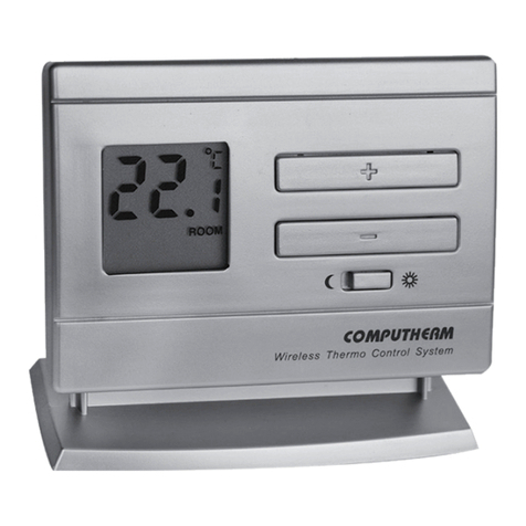
Below the temperature adjustment buttons ( and )
a switch is located. For both the economy (w
) and the comfort
(☼) positions of the switch a dierent temperature can be set
between 5 °C and 40 °C, in steps of 0.5 °C.
For energy eciency it is recommended that the comfort temperature is only
used those times, when the room or building is in use, because every 1 °C de-
crease of temperature saves approximately 6% energy during a heating season.
The factory default temperature is 18 °C for the economy (w
) position and 20
°C for the comfort (☼) position. These default temperatures can be changed as
follows:
• Move the switch according to the temperature you would like to change
(economy (w) or comfort (☼)).
• Press the or button, after which the notice “ROOM” disappears,
the notice “SET” (adjusted value) appears in the bottom right corner of the
display. Meanwhile, the temperature value shown on the display switches
from room temperature to the default temperature (18.0 °C/20.0 °C) or to
the last set temperature (this temperature is blinking on the display). By
pressing the buttons repeatedly or continuously (the change in values is
accelerated), the desired temperature to be maintained at the place where
the thermostat has been installed can be set in steps of 0.5 °C.
• Approximately 6 seconds after setting the room temperature to be main-
tained, the device automatically switches to normal mode. The notice “SET”
disappears from the bottom right corner of the display, and once again the
current room temperature and the notice “ROOM” are displayed.
• The previously set temperature can be freely changed any time using the
and buttons. Always the last set temperatures are in eect.
5. OPERATION OF THE INSTALLED THERMOSTAT
The thermostat controls the device connected to it (e.g. gas boiler or pump)
based on the temperature measured by it and the currently set temperature,
taking into account the switching sensitivity of the thermostat (factory default
±0.2 °C). This means that if the thermostat is set to heating mode and 22 °C,
then with a switching sensitivity of ±0.2 °C the connection points NO and COM
of the receiver output relay are closed below 21.8 °C (heating is turned on) and
230 V AC is displayed on the output for that zone and NO and COM opened at
temperatures above 22.2 °C (heating is turned o) and the 230 V AC voltage at
