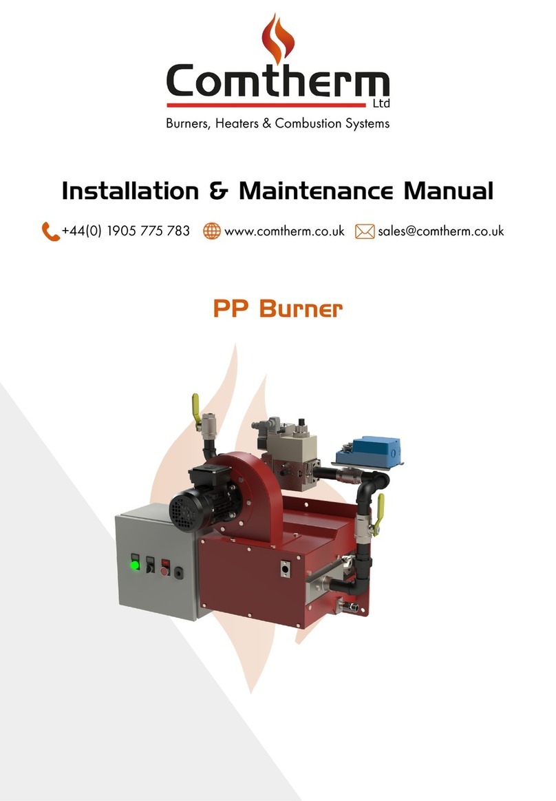
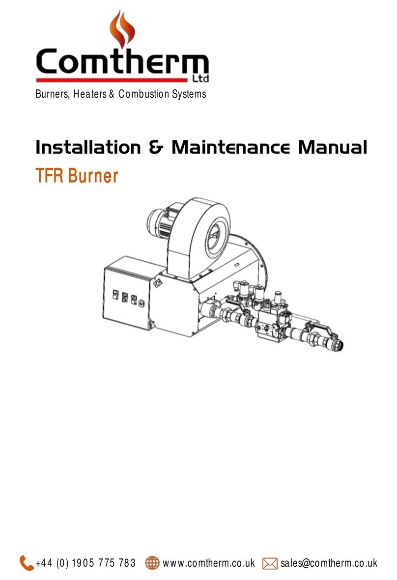
The burner consists of a gas manifold assembly having fuel and air jets designed to produce
effective mixing of the fuel and combustion air hence providinggood flame stability.
The manifold assembly is fitted with integral ignition and flame sensor facilities.
The unit comes complete with all the valves and controls required; forming a fully packed, safe
burner assembly.
The valves and controls are pre-piped and mounted on the burner side plate, as illustrated
diagrammatically in document M4. Pressure test points are fitted between valves where
necessary.
The physical arrangement of the burner is shown in diagram form in document M3 (where
applicable).
All the electrical equipment on the unit is pre-wired to a terminal enclosure on the assembly,
as detailed in the burner wiring diagram (document M5).
The electrical operation of the burner is as follows:
When the electrical supply is switched on to the burner and all the control circuits are closed,
the burner light up sequence is initiated.
The burner flame safety sequence control unit (unit A1) receives the electrical start signal and
begins to cycle through an air pre-purgeand light up sequence.
The air pre-purge is for a specified, preset time and allows for dilution of any fuel leakage; to
safeguard against the possibility of explosive fuel/air mixture being present in the burner duct
when the ignition is energized.
After the completion of the pre-purge,the ignition and flame proving periodtake place.
When the flame signal is proven, the burner sequence control remains in the operating
position until any of the control circuit interlocks are broken or a flame failure (lockout)
condition occurs.
Complete details of the burner light-up sequence including the flame safety control unit (item
A1) will be found in the component data sheet, enclosed.
For details on installation and commissioning, refer to pageM6-1-2-3.
NOTE: -
Refer to M9-1 and M9-2 for key to items referredto throughout this manual.
Refer to M9-3 for specific component manufacturersused on this equipment
General Description
Comtherm Ltd
Installation & Maintenance Manual Page 02
Burners, Heaters & Combustion Systems


