Connective Peripherals ES-U-2001-STB User manual

Connective Peripherals Pte Ltd
178 Paya Lebar Road, #07-03 Singapore 409030
Tel.: +65 67430980 Fax: +65 68416071
E-Mail (Support): support@connectiveperipherals.com Web: www.connectiveperipherals.com/products
Neither the whole nor any part of the information contained in, or the product described in this manual, may be adapted, or reproduced in any material
or electronic form without the prior written consent of the copyright holder. This product and its documentation are supplied on an as-is basis and no
warranty as to their suitability for any particular purpose is either made or implied. Connective Peripherals Pte Ltd will not accept any claim for damages
howsoever arising as a result of use or failure of this product. Your statutory rights are not affected. This product or any variant of it is not intended for
use in any medical appliance, device, or system in which the failure of the product might reasonably be expected to result in personal injury. This
document provides preliminary information that may be subject to change without notice. No freedom to use patents or other intellectual property
rights is implied by the publication of this document. Connective Peripherals Pte Ltd, 178 Paya Lebar Road, #07-03 Singapore 409030. Registered
Number: 201617872E
Copyright © Connective Peripherals Pte Ltd
ES-U-2001-STB
USB to Industrial Single RS-422/485
Adapter Installation Guide
Document Reference No.: CP_000075
Version 1.1
Issue Date: 01-04-2022

ES-U-2001-STB Installation Guide
Version 1.1
Document Reference No.: CP_000075 Clearance No.: CP#063
Copyright © Connective Peripherals Pte Ltd 2
Table of Contents
1Introduction ............................................................3
2Specifications & Features ........................................4
3Hardware Setup.......................................................5
3.1 General notes ................................................................ 5
3.2 RS422/RS485 Mode Switch ........................................... 6
3.3 Termination and Biasing Configuration.......................... 7
4Driver Installation & Verification .............................9
5Pin Layouts / Pinout information...........................10
5.1 RS-422 Signal Pin-outs of Terminal Block.................... 10
5.2 RS-422 Signal Wiring................................................... 10
5.2.1 Point-to-Point 4 Wire Full Duplex...................................................... 10
5.3 RS-485 4-Wire (Full duplex) Signal Pin-outs of Terminal
Block 10
5.4 RS-485 2-Wire (Half duplex) Signal Pin-outs of Terminal
Block 10
5.5 RS-485 Signal Wiring................................................... 11
5.5.1 Point-to-Point 4-Wire Full Duplex...................................................... 11
5.5.2 Multi-drop RS-485 2-Wire Half-duplex............................................... 11
6Contact Information ..............................................12
Appendix A - List of Figures & Tables .........................13
List of Figures........................................................................ 13
List of Tables ......................................................................... 13
Appendix B - Revision History ....................................14

ES-U-2001-STB Installation Guide
Version 1.1
Document Reference No.: CP_000075 Clearance No.: CP#063
Copyright © Connective Peripherals Pte Ltd 3
1Introduction
The ES-U-2001-STB USB to Industrial Single RS-422/485 Adapter is designed to make serial port
expansion quick and simple. Connecting to a USB port on your computer or USB hub, the USB Serial
Adapter instantly adds one industrial RS-422/485 interface serial communication port to your system.
By taking advantage of the USB bus, the USB Serial Adapter makes it easier than ever to add one
RS-422/485 port and serial devices to your system with easy plug and play and hot plug features.
Plugging the ES-U-2001-STB into the USB port, the adapter is automatically detected and installed.
There are no IRQ & COM port conflicts, since the port doesn't require any additional IRQ, DMA,
memory as resources on the system. The RS-422/485 port functions as native Windows COM port,
and it is compatible with Windows serial communication applications. The adapter is designed with
external switches to set the unit to the RS-422 or RS-485 modes. The upper-case slides open easily
for configuration and mode setting.
The USB Serial Adapter provides instant connectivity to RS-422/485 communication devices for
factory automation equipment, multi-drop data collection devices, barcode readers, time clocks,
scales, data entry terminals, ATMs, and serial communication in harsh environment. The USB to Serial
Adapter is suitable for remote access, retail and industrial applications, data collection and other
applications requiring high speed RS-422/485 communication ports.

ES-U-2001-STB Installation Guide
Version 1.1
Document Reference No.: CP_000075 Clearance No.: CP#063
Copyright © Connective Peripherals Pte Ltd 4
2Specifications & Features
•FTDI USB-Serial chipset and drivers
•Adds one RS-422 / 485 serial ports via USB connection.
•256 bytes receive buffer.
•128 bytes transmit buffer for high-speed data throughput.
•Requires no IRQ, DMA, I/O port.
•Data rates: 300 bps to 1M bps.
•Connector: one 5-pin terminal block.
•Auto transmit buffer control for 2-wire RS-485 half-duplex operation.
•Termination resistors installed on-board.
•RS-422 data signals: Tx-, Tx+, Rx+, Rx-, GND.
•RS-485 data signals: Tx-, Tx+, Rx+, Rx-(4 wire) and data-, data+ (2 wire).
•Indication LEDs for TxD and RxD port status.
•Easy operating mode configuration and setting
•Virtual COM port drivers for Windows, Linux and macOS

ES-U-2001-STB Installation Guide
Version 1.1
Document Reference No.: CP_000075 Clearance No.: CP#063
Copyright © Connective Peripherals Pte Ltd 5
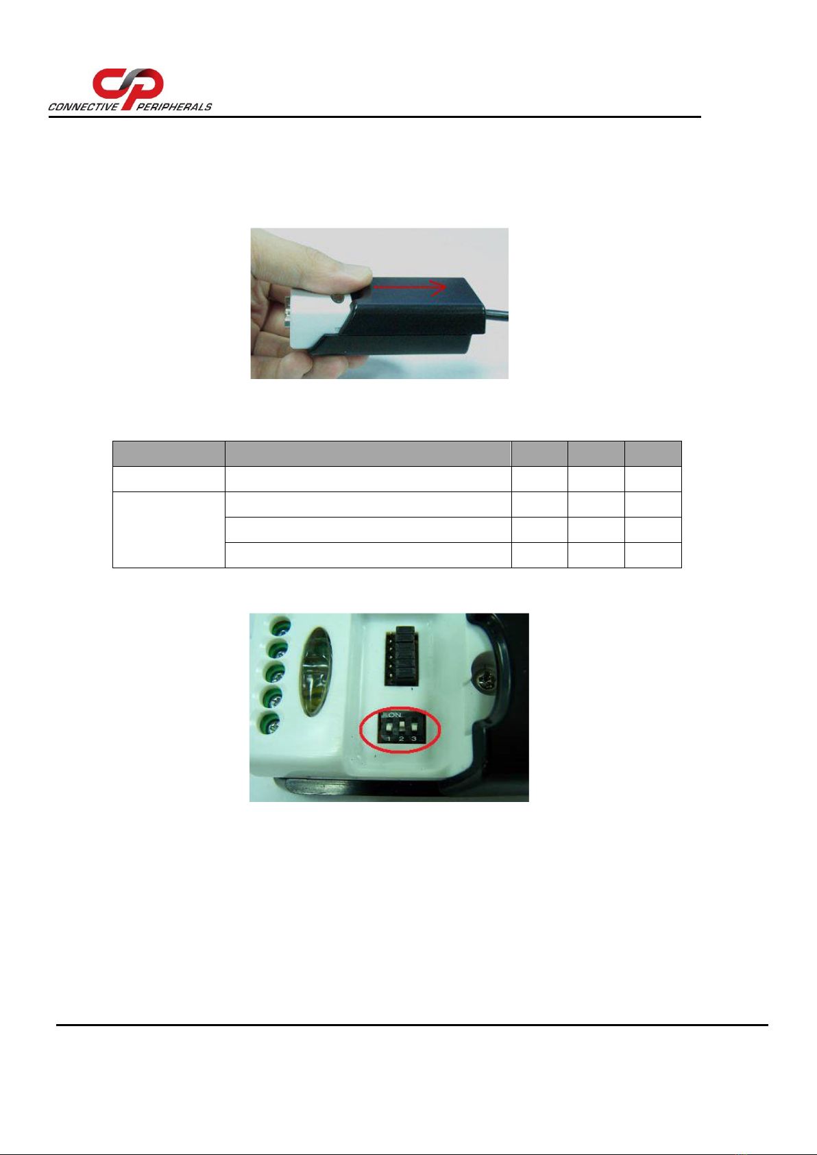
3Hardware Setup
Before connecting the unit to the RS422/RS485 bus or to the computers USB port, you should set up
the hardware switches and jumpers.
3.1 General notes
Serial Bus Configuration
It is important to configure the DIP switches and jumpers to select the correct type of serial bus (RS-
422 or RS-485) for your application before connecting the converter to your serial bus. Otherwise,
damage can occur to the converter or other equipment on the RS-422/RS-485 bus.
To avoid damage, the serial cables and USB cable should be disconnected from your converter before
changing DIP switch settings and before opening the case to change jumper settings.
Termination
For RS-422 or RS-485, it may be necessary to enable termination of the data transmission lines. This
depends on the way in which your network is connected and if termination is already provided by
other devices on the network. Before applying the termination, check your cable specification for
proper impedance matching. The termination option connects a 120 Ohm resistor between the data
+ and - lines.
Termination is normally used in the node at each end of the bus, but nodes in the middle of the bus
should not have termination enabled. Enabling termination resistors on additional nodes which are
not at the ends of the bus may cause overloading of the line drivers leading to unreliable operation
of the unit and the overall system.
ES-U-2001-STB converters have jumpers to allow the internal termination resistors to be enabled if
required. This avoids the need to provide an external resistor at the ES-U-2001-STB end of the bus.
There are separate jumpers for Tx+/Tx- termination and Rx+/Rx- termination allowing termination
to be enabled for either or both if required. When using RS-485 half-duplex, the Tx and Rx pairs are
combined into a single bi-directional pair and so only the Tx+/Tx- termination should be enabled. The
Rx+/Rx- termination should be disabled.
Biasing
In some cases, the RS-485 lines may float to undefined levels when no transmitter is active, and this
can cause additional unexpected characters to appear at the start or end of a message. Biasing
resistors are used to set a defined logic level on the serial lines when no node is transmitting. 750
Ohm resistors pull up the Data + line and pull down the Data –line.
ES-U-2001-STB converters feature internal biasing resistors with jumpers to enable/disable them.
These should be disabled if another device on your serial bus already provides biasing as biasing of
data lines must only occur at a single point in the cabling. Fitting more than one set of bias resistors
can cause overloading of the line drivers leading to unreliable operation of the unit and the overall
system.
There are four jumpers to select biasing on Tx+, Tx-, Rx+ and Rx-. When using RS-485 half-duplex,
the Tx and Rx pairs are combined into a single bi-directional pair and so only the jumpers for Tx
biasing (Pull up of Tx+ and Pull down of Tx-) should be fitted. The Rx biasing should be disabled.

ES-U-2001-STB Installation Guide
Version 1.1
Document Reference No.: CP_000075 Clearance No.: CP#063
Copyright © Connective Peripherals Pte Ltd 6
3.2 RS422/RS485 Mode Switch
Inside the unit, there is a 3-way DIP switch which is set to select the mode of operation. You will
need to push down the upper case (refer to the picture) and set the switch settings to RS-422 or RS-
485 mode as per the requirements of your application. After setting of switches, you then plug the
adapter to USB port to start driver installation. The modes are shown in Table 1.
Figure 1 –Push down the upper case and slide it to open
The RS-422 and RS-485 Mode block configuration settings are listed below -
Operation Mode
S1
S2
S3
RS-422
4 wires with Handshaking
OFF
ON
OFF
RS-485
Full Duplex (4 wire)
ON
ON
OFF
Half Duplex (2 wire) - with Echo
ON
OFF
OFF
Half Duplex (2 wire) - without Echo
ON
OFF
ON
Table 1 - RS-422 & RS-485 Mode Block Configuration SW (External DIP Switch) for
Mode Setting
Figure 2 - 3-way DIP Switch for Operating Mode Selection

ES-U-2001-STB Installation Guide
Version 1.1
Document Reference No.: CP_000075 Clearance No.: CP#063
Copyright © Connective Peripherals Pte Ltd 7
3.3 Termination and Biasing Configuration
Inside the unit, there is a 6 x 3 header block. This allows jumpers to be fitted to enable Tx and Rx
120 Ohm termination resistors and to enable the Tx and Rx 750 Ohm biasing resistors.
Figure 3 –6 x 3 Header Block to enable Termination & Biasing Resistors
You will need to open the upper case and set the jumpers as per the requirements of your application.
The jumpers control the following settings. Please refer to the notes on the following page before
setting the jumpers.
Jumper
Function
1-2 enable
Tx+/- Termination of 120 Ohm (see notes below table)
2-3 disable
4-5 enable
Pull-up Tx+ to VCC via 750 Ohm Bias resistor (see notes below table)
5-6 disable
7-8 enable
Pull-down Tx- to GND via 750 Ohm Bias resistor (see notes below table)
8-9 disable
10-11 enable
Rx+/- Termination of 120 Ohm (see notes below table)
11-12 disable
13-14 enable
Pull-up Rx+ to VCC via 750 Ohm Bias resistor (see notes below table)
14-15 disable
16-17 enable
Pull-down Rx- to GND via 750 Ohm Bias resistor (see notes below table)
17-18 disable
Table 2 - Termination and Biasing Jumpers
Note on Termination:
For RS485 half-duplex, if termination is required, only Tx Termination should be enabled as the
Tx and Rx lines are linked. Enable Tx+/- termination (jumper 1-2) and disable Rx+/- termination
(jumper 11-12)
For RS485 full-duplex and RS422, termination can be enabled/disabled for Tx+/- and Rx+/- pairs
independently using the jumpers as required.
See the notes on Termination in section 3.1 before setting these options.

ES-U-2001-STB Installation Guide
Version 1.1
Document Reference No.: CP_000075 Clearance No.: CP#063
Copyright © Connective Peripherals Pte Ltd 8
Note on Biasing:
For RS485 half-duplex, if biasing is required, enable Tx+/- biasing only (jumper 4-5 and 7-8) and
disable Rx+/- biasing (jumper 14-15 and 17-18)
For RS485 full-duplex and RS422, biasing can be enabled/disabled for Tx+/- and Rx+/- pairs
independently as required.
See the notes on Biasing in section 3.1 before setting these options.

ES-U-2001-STB Installation Guide
Version 1.1
Document Reference No.: CP_000075 Clearance No.: CP#063
Copyright © Connective Peripherals Pte Ltd 9
4Driver Installation & Verification
Once the jumpers and switches have been configured using the previous sections in this guide, the
driver can be installed.
For information on driver installation and connecting the converter to your computer, please refer to
the Connective Peripherals USB to Serial Converters Driver Installation Guide (Document CP_000084)
which is available from www.connectiveperipherals.com

ES-U-2001-STB Installation Guide
Version 1.1
Document Reference No.: CP_000075 Clearance No.: CP#063
Copyright © Connective Peripherals Pte Ltd 10
5Pin Layouts / Pinout information
5.1 RS-422 Signal Pin-outs of Terminal Block
Pin 1
TxD- (A)
Pin 2
TxD+(B)
Pin 3
RxD+(B)
Pin 4
RxD-(A)
Pin 5
GND
5.2 RS-422 Signal Wiring
5.2.1 Point-to-Point 4 Wire Full Duplex
5.3 RS-485 4-Wire (Full duplex) Signal Pin-outs of Terminal
Block
Pin 1
TxD- (A)
Pin 2
TxD+(B)
Pin 3
RxD+(B)
Pin 4
RxD-(A)
Pin 5
GND
5.4 RS-485 2-Wire (Half duplex) Signal Pin-outs of Terminal
Block
Pin 1
Data- (A)
Pin 2
Data+(B)
Pin 5
GND

ES-U-2001-STB Installation Guide
Version 1.1
Document Reference No.: CP_000075 Clearance No.: CP#063
Copyright © Connective Peripherals Pte Ltd 11
5.5 RS-485 Signal Wiring
5.5.1 Point-to-Point 4-Wire Full Duplex
5.5.2 Multi-drop RS-485 2-Wire Half-duplex

ES-U-2001-STB Installation Guide
Version 1.1
Document Reference No.: CP_000075 Clearance No.: CP#063
Copyright © Connective Peripherals Pte Ltd 12
6Contact Information
Global Headquarters –Singapore
Connective Peripherals Pte Ltd
178 Paya Lebar Road
#07-03
Singapore 409030
Tel: +65 67430980
Fax: +65 68416071
Web Site URL http://www.connectiveperipherals.com
Web Shop URL http://www.connectiveperipherals.com

ES-U-2001-STB Installation Guide
Version 1.1
Document Reference No.: CP_000075 Clearance No.: CP#063
Copyright © Connective Peripherals Pte Ltd 13
Appendix A - List of Figures & Tables
List of Figures
Figure 1 –Push down the upper case and slide it to open .............................................6
Figure 2 - 3-way DIP Switch for Operating Mode Selection ...........................................6
Figure 3 –6 x 3 Header Block to enable Termination & Biasing Resistors .....................7
List of Tables
Table 1 - RS-422 & RS-485 Mode Block Configuration SW (External DIP Switch) for
Mode Setting .................................................................................................................6
Table 2 - Termination and Biasing Jumpers ...................................................................7

ES-U-2001-STB Installation Guide
Version 1.1
Document Reference No.: CP_000075 Clearance No.: CP#063
Copyright © Connective Peripherals Pte Ltd 14
Appendix B - Revision History
Revision
Changes
Date
1.0
Initial release
29-12-2020
1.1
Updated biasing/termination section to provide
better description. Moved driver install section to
USB to Serial Converters Driver Installation Guide
available from www.connectiveperipherals.com
01-04-2022
Table of contents
Other Connective Peripherals Adapter manuals

Connective Peripherals
Connective Peripherals USB2-F-1001 User manual

Connective Peripherals
Connective Peripherals USB2-F-5001 User manual

Connective Peripherals
Connective Peripherals ES-U-2001-S User manual

Connective Peripherals
Connective Peripherals USB2-H-6002 User manual

Connective Peripherals
Connective Peripherals USB2-H-5002 User manual

Connective Peripherals
Connective Peripherals USB2-H-9004-M User manual

Connective Peripherals
Connective Peripherals USB2-H-1004 User manual

Connective Peripherals
Connective Peripherals USB2-H-5004 User manual

Connective Peripherals
Connective Peripherals USB2-F-6001 User manual

Connective Peripherals
Connective Peripherals USB2-H-1001 User manual