manuals.online logo
Brands
  1. Home
  2. •
  3. Brands
  4. •
  5. Connectix
  6. •
  7. Cables And Connectors
  8. •
  9. Connectix XP Fit Plus SC 900 mm User manual

Connectix XP Fit Plus SC 900 mm User manual

Popular Cables And Connectors manuals by other brands

StarTech.com ST124HD20 quick start guide

StarTech.com

StarTech.com ST124HD20 quick start guide

Philips SWV4543S/10 Features

Philips

Philips SWV4543S/10 Features

Larson Electronics 10-50C instruction manual

Larson Electronics

Larson Electronics 10-50C instruction manual

Grip MEK-PM Assembly and operating manual

Grip

Grip MEK-PM Assembly and operating manual

Ultra Products Travel Pack #3 ULT31436 Specifications

Ultra Products

Ultra Products Travel Pack #3 ULT31436 Specifications

Surpass QCH-F Operation manual

Surpass

Surpass QCH-F Operation manual

Philips SWA6310 Specifications

Philips

Philips SWA6310 Specifications

StarTech.com CRJ4550PK quick start guide

StarTech.com

StarTech.com CRJ4550PK quick start guide

Nohau EMUL-IP2K-PC user guide

Nohau

Nohau EMUL-IP2K-PC user guide

Foxun SX-SP144E-HD4K2K operating instructions

Foxun

Foxun SX-SP144E-HD4K2K operating instructions

Philips SWA3305W Specifications

Philips

Philips SWA3305W Specifications

opticis Stretch DVIM1-1P0x user manual

opticis

opticis Stretch DVIM1-1P0x user manual

Volkswagen VAS 6558A operating manual

Volkswagen

Volkswagen VAS 6558A operating manual

NEXIBO N-13 user manual

NEXIBO

NEXIBO N-13 user manual

CYP PU-1H3HBTL Operation manual

CYP

CYP PU-1H3HBTL Operation manual

Allen-Bradley 1784-u2dhp installation instructions

Allen-Bradley

Allen-Bradley 1784-u2dhp installation instructions

Global Caché Flex Link Blaster quick start

Global Caché

Global Caché Flex Link Blaster quick start

Hauppauge USB-Live2 Quick installation guide

Hauppauge

Hauppauge USB-Live2 Quick installation guide

manuals.online logo
manuals.online logoBrands
  • About & Mission
  • Contact us
  • Privacy Policy
  • Terms and Conditions

Copyright 2025 Manuals.Online. All Rights Reserved.

Assembling tools example
For your safety operation
This product has been designed and manufactured to
assure personal safety. Improper use can result in bodily
injury and serious damage to the product. Please read
and observe all warnings and instructions given in this
operation manual.
Improper assembly will result in a loss of performance.
Please read instructions given in this operation manual.
The product is sensitive to dirt and dust.
The performance will be influenced by the fiber cutting
surface condition. Use a cutter with a sharp blade for the
best results.
Please insert the fiber into the connector slowly. If the
fiber is roughly inserted, it might be damaged or broken,
leading to failure of connector installation. Broken fiber
could scatter in all directions.
Do not remove the dust cap until the connector has
been completely assembled in order not to cause a high
insertion loss.
A proper amount of index matching gel is applied in the
connector. Do not insert fiber more than once into
connector.
1.
2.
3.
4.
5.
6.
XP Fit Plus SC 900 μm
Field Installable Connector
Instruction Manual
Wear safety glasses before handling optical fiber to
protect the eyes. Small pieces of glass fibers are sharp
and can cause damage if they get in the eyes or
puncture skin if handled wrong.
Never look into the end of a connector or an optical fiber
which may have a laser coupled to it. Laser light might
damage your eyes. Please note that laser light is not
visible.
When working off of the ground, please be careful not to
drop an assembling tool.
Connector (with wedge): 10pcs
Boot: 10pcs
Fiber holder for 0.9 wire: 1pc
Assembling Jig:1pc
Following tools shall be required adding above parts,
 1. Fiber Cleaver
 2. Jacket Remover
For your safety operation Precautions
Precautions
Composition
Composition
(Please use a wrist strap etc.)
Fiber cleaver
Jacket remover
Boot
XP Fit plus SC 900μm
Assembling Jig
Fiber Holder for
0.9 wire
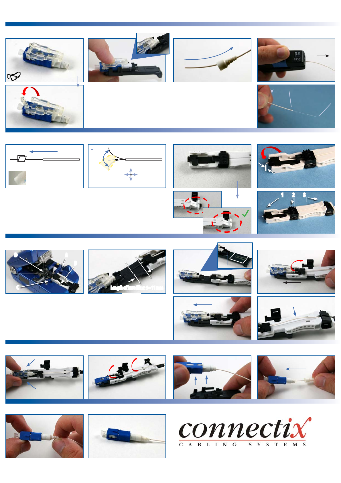
7- Setting Fiber on the Fiber Holder
A C
Close the front cover
B D
11 - Remove the Wedge 12 - Open the Front and Back Cover 13 - Take out Connector 14 - Fitting Boot
8- The Fiber Cleaver 9- Checking Cut Dimension
5- Cleaning Bare Fiber 6- Screening Fiber
2- Setting Connector 3- Install boot onto ber as shown 4- Removing 0.9 Wire Coating
AGrip
B
15 - Completion
1- Preparing Connector
A
B Open the lock lever
10 - Inserting Fiber
A C 1. Open the middle cover
B D
Small amount of bending is normal
Be sure to wear Safety Glasses
2 - Set circular groove of connector
tightly onto semicircular ridge “U”
shaped shelf of Jig.
Make sure there is no space between the
wedge and the connector, if there is, re-
align the products before proceeding.
Approximately 30 mm
4 A - Remove 0.25 mm or 0.9 mm ber
jacket remover. coating, using
appropriate ber jacket remover.
4 B - Removing appropriate length of
the ber jacket
Pull
5 - DO NO T USE DIRTY GAUZE!
6  Bend ber several times by moving it
with your nger back and fourth.
IF FIBER BRAKES, START WITH A
NEW FIBER FROM THE BEGINNING.
7B - When fully pushed forward guide
member should not be visible from the
back end of the ber holder
7D- SETTHE FIBER ALONG THE GROOVE
TIGHTLY BEFORE CLOSING THE BACK COVER.
8 - A - Insert slider
B - Set the ber holder to the Cleaver
C - Set the ber holder tightly
D - Push the cover of the Cleaver
SET THE FIBER HOLDERTIGHTLY!
A
B
C
D
10A -
Set the ber holder to the guiding rail
10 B - Slide holder slowly until it is stopped.
BE CAREFUL NOTTO HIT THE EDGE OF FIBER!
10C  See diagram
10D  CHECKING WHETHERTHE FIBER IS
BENDING OR NOT IMPORTANT!
Guiding Rail
Length of bare ber: 9~11 mm
CLICK!
Push the arm to remove the wedge PULL OUT WEDGE AND OPEN COVER.
CLICK!
IF OUT OF TOLERANCE,
REWORK FROM
PROCEDURE4!
Close the cover in the order of above
LENGTH OF 0.9 BUFFER IS WITHIN 2 MM!
<2mm
1 2 3
X
Clean bare ber with a lint-
free Gauze Pad moistened
with pure Alcohol
X
up
down
left right
30o
degree
GUIDE MEMBER MUST BE PUSHED AS
FAR FORWARD AS POSSIBLE.
2. Insert until sounding click