3
Yellow
spring is standard,
but
to increase engagement A.P.M. you
c
ould
install
a green spring
which
is stronger.
Part
Number
Color S
pr
ing
Compress
ion
Rate
050760 Y
ellow
50 Ibs. @in.
050786 Green 64 Ibs. @in.
NOTE : New
springs
will
have a
higher
ten
sion
than a used
spr
ing.
Norm
ally
, a
spring
will
"se
at"
afte
r approx
imate
ly 50
mil
es. Be sure to install a used
spring
when
adju
sting
your
drive
system
s
ince
spring
change
s
could
later alter y
our
ad-
ju
stments
.
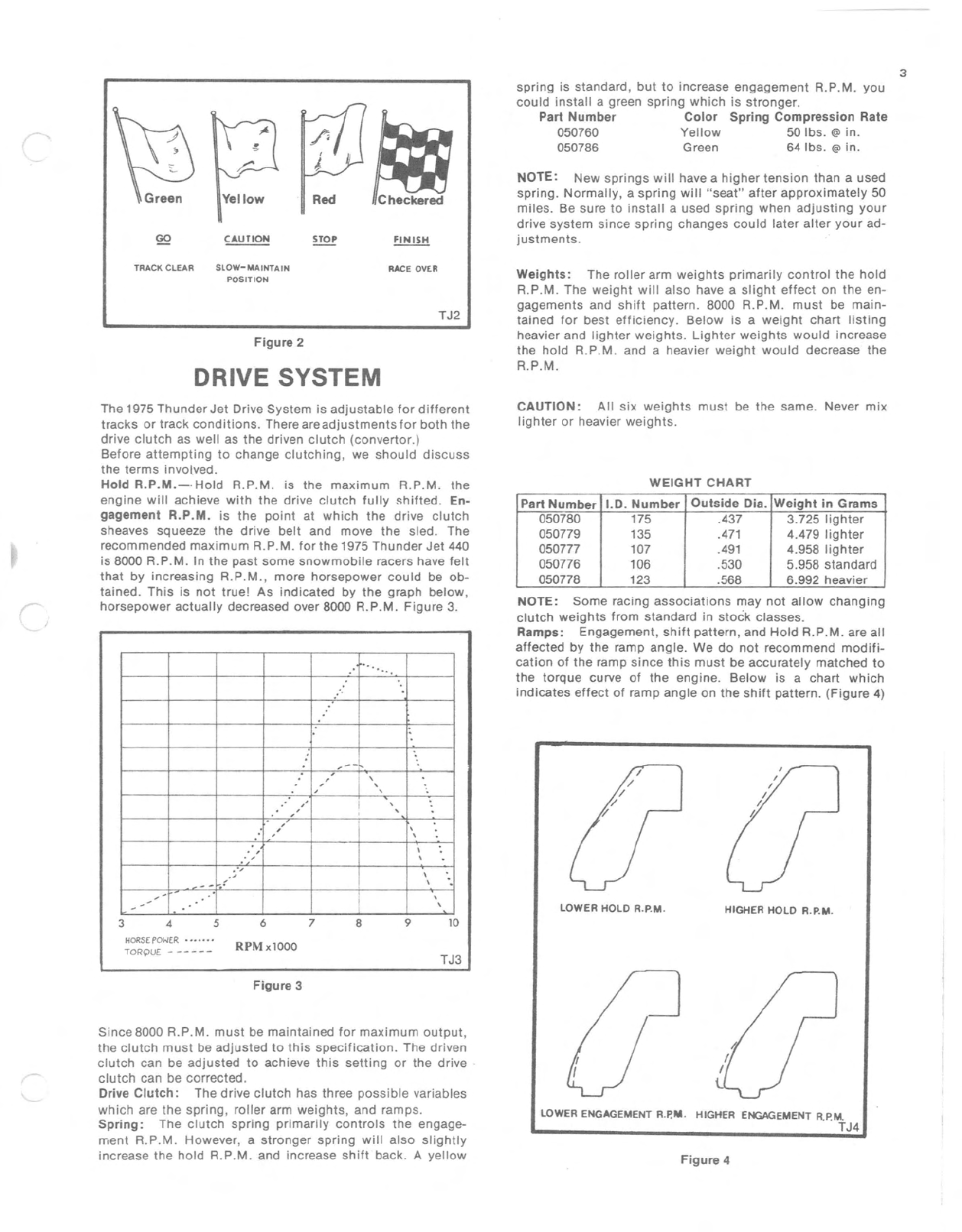
TRACK CLEAR
SLOW-MAINTA
IN RACE OVER
POSITION
TJ2
Figure 2
DRIVE SYSTEM
Weights: The
roller
arm
weights
primari
ly
control
the
hold
A.P.M. The
weight
will
also
have a
slight
effect
on the en-
gagements and
shift
pattern. 8000 A.P.M. must be
main
-
t
aine
d
for
best
efficiency.
Below
is a
weight
chart
li
sting
heavier and
lighter
weights.
Lighter
wei
ghts
would
incr
ease
the
hold
A
.P.M
. and a heavier
weight
would
decrease the
A.P.M .
WEIGHT
CHART
CAUTI
ON:
All six
weights
must
be the same. Never
mix
lighter
or heavier
weights
.
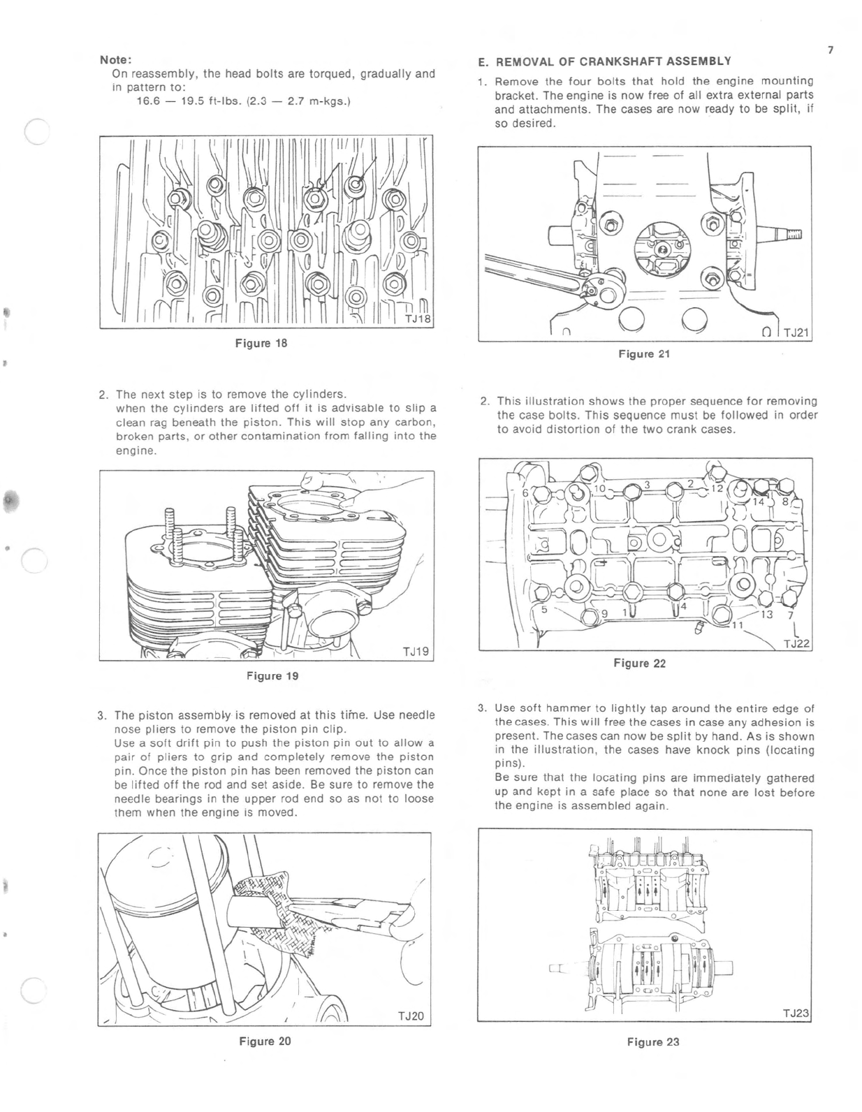
HIGHER HOLD R.P.M.
LOWER HOLD R.P.M.
NOTE: Some ra
cing
as
sociations
may not allow changing
clutch wei
ght
s
from
standard in stock classes.
Ramps:
Engagement, shift p
att
ern, and Hold A.P.M. are all
affected by the r
amp
angl
e. We do
not
re
com
mend
mod
ifi-
cation of the ramp
since
this
must be accurately matched to
the torque curve of the
engi
ne. Below is a chart which
indi
cates e
ffe
ct of ramp angle on the shift pattern. (
Fig
ure 4)
Part Number 1.0.
Num
ber
Out
side
Dia. Wei
ght
in
Grams
050780 175 .437 3.725 li
ght
er
050779 135 .471 4.479
ligh
ter
050777 107 .491 4.958
light
er
050776 106 .530 5.958 standard
050778 123 .568 6.992 heavier
'.'."
:
,
--
,\
,,\
,-,
,,,
,,,
:
,/
,
,,
,\
,\
."
\
.'
--r\.
,-\
-,,
-
The 1975
Thunder
Jet
Drive
System
is ad
justable
for
different
tracks
or track cond
itions
. There are
adjustments
for
both
the
drive c
lutch
as well as the driven
clutch
(convertor.)
Before
attempt
ing to
change
clutch
ing , we
should
d
iscuss
the
terms
involved.
Hold
R.P.M.-
·Hold
A.P
.M.
is the
maximum
A.P.M . the
eng ine
will
achieve
with
the drive
clutch
fully
shifted
. En-
gagement
R.P.M
. is the po
int
at
which
the
drive
clutch
sheaves squeeze the
drive
b
elt
and move the sled . The
recommended
maximum
A.P.M.
for
the 1975
Thunder
Jet
440
is 8000 A.P
.M.
In the
past
some
snowmobile racers have
felt
that
by increa
sing
A.P.M ., more
hors
epow
er
could
be ob-
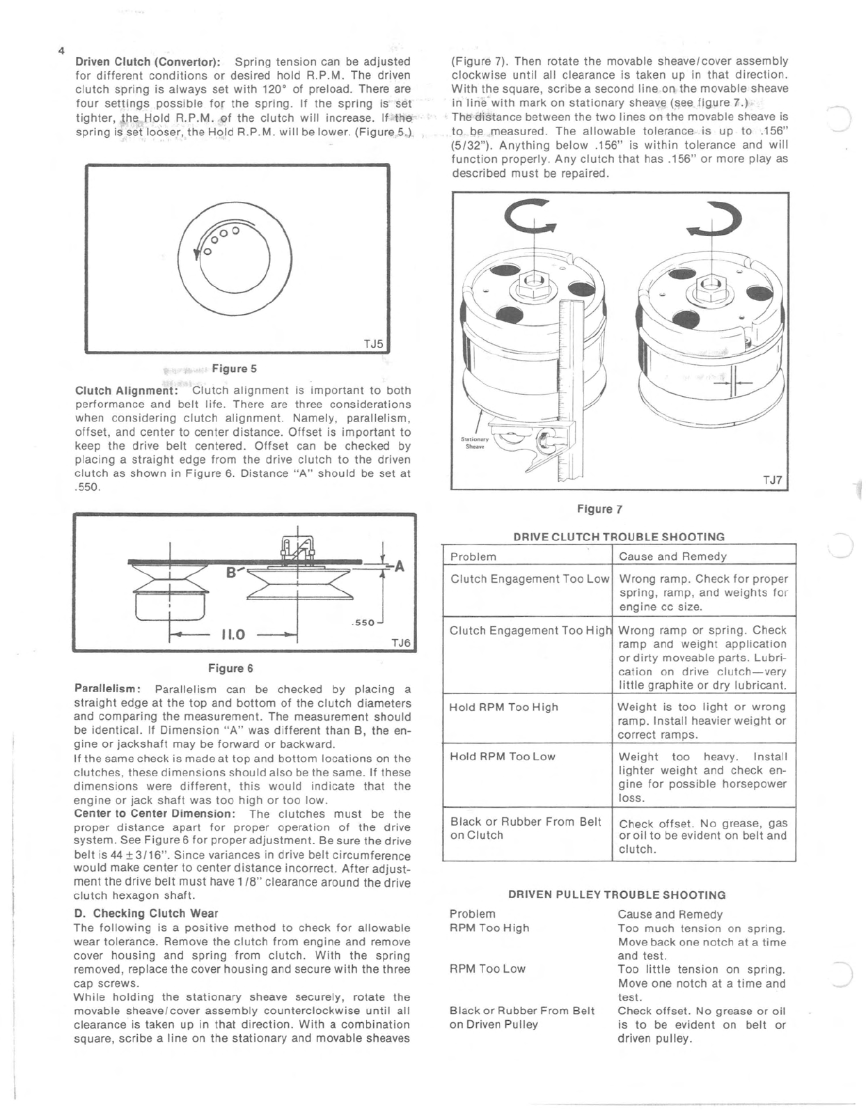
tained. This is not tru e! As
indic
ated by the graph
below
,
hors
epower
a
ctually
d
ecr
eased over 8000 A.P.M .
Figure
3.
345678910
HoRSE
POWER
....
.
..
RPMxl000
TORQ
UE -
--
---
TJ3
Figure 3
Since
8000 A.P.M.
must
be
maintained
for
maximum
output
,
the
clutch
must
be
adjusted
to th is
specification
. The driven
clutch
can be
adjusted
to achieve
this
setting
or the drive ·
clutch
can be corrected.
Drive
Clutch:
The drive
clutch
has three
possible
variables
which
are the
spring
,
roller
arm
weights,
and ramps.
Sprin
g:
The c
lutch
spr
ing
primarily
controls
the engage-
ment A
.P.M.
However, a
stronger
spring
will
also
slightly
increase the hold A.P.M. and increase shift back . A
yellow
LOWER ENGAGEMENT R.p,M. HIGHER ENGAGEMENT R.P.M.
TJ4
Figure
4