CONTINENTAL EDISON BANDEAU HP F1 User manual

SECHE LINGE
MANUEL DE SERVICE
HP F1
BANDEAU

CONTENTS
1. OVERVIEW AND WORKING PRINCIPLE................................................................................................ 4
1.2. Working Principle: ........................................................................................................................ 4
2. TECHNICAL SPECIFICATIONS................................................................................................................ 5
3. INSTALLATION ..................................................................................................................................... 5
3.1. Issues that should be informed to customer ............................................................................... 5
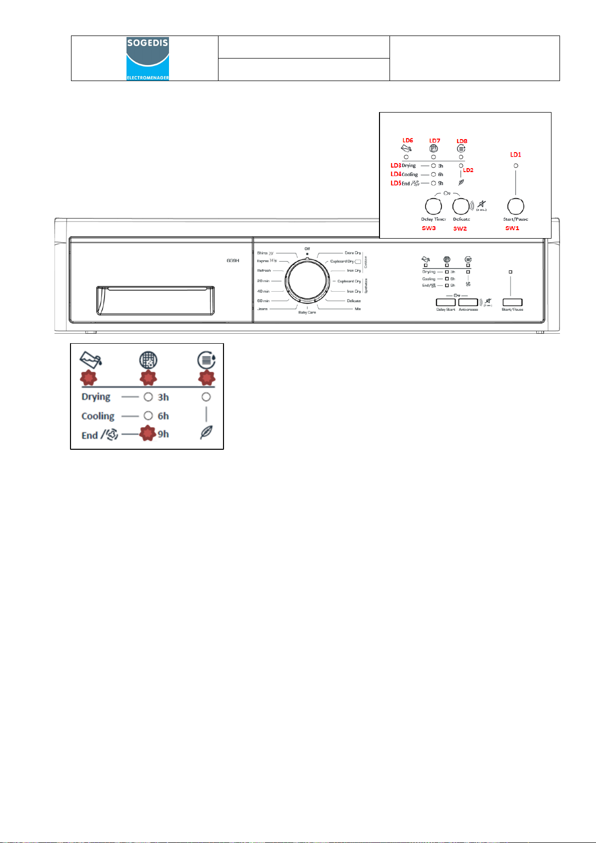
4. CONTROL PANEL AND PROGRAM SELECTION TABLE.......................................................................... 6
4.1. Control Panel................................................................................................................................ 6
4.2.Program List .................................................................................................................................. 6
5.FAILURE MODES AND SERVICE AUTOTEST........................................................................................... 8
5.1. Failure Modes and Warning Leds................................................................................................. 9
5.2.Service Auto Test Steps............................................................................................................... 10
6. DISASSEMBLY..................................................................................................................................... 11
6.1. Top Plate..................................................................................................................................... 11
6.2. Control Panel.............................................................................................................................. 12
6.3. Electronic Card ........................................................................................................................... 15
6.4. Side Panel ................................................................................................................................... 18
6.5. Supply Cable ............................................................................................................................... 20
6.6. Emi Filter..................................................................................................................................... 21
6.7. Rear Cover.................................................................................................................................. 22
6.8.Pump ........................................................................................................................................... 23
6.9.Process Fan.................................................................................................................................. 25
6.10. Rear Panel................................................................................................................................. 26
6.11. Rear Isolation Group ................................................................................................................ 28
6.12. Rear Bearing Group .................................................................................................................. 29
6.13. Water Tank Housing................................................................................................................. 30
6.14. Drum......................................................................................................................................... 31
6.15. Motor ....................................................................................................................................... 32
6.16. Capacitors................................................................................................................................. 34
6.17. Belt ........................................................................................................................................... 35
6.18. Humidity Sensor ....................................................................................................................... 36
6.19. Door latch................................................................................................................................. 37
6.20. Plinth ........................................................................................................................................ 38
6.21. Cooling Fan............................................................................................................................... 39

6.22. Plinth Cover .............................................................................................................................. 40
6.23. Door.......................................................................................................................................... 41
6.24. Drum Bearing Wheel ................................................................................................................ 42
6.25. Drumlight.................................................................................................................................. 43
6.26. Front Panel ............................................................................................................................... 44
6.27. Door NTC .................................................................................................................................. 45
6.28. Side Bracket.............................................................................................................................. 46
6.29. Front Shield .............................................................................................................................. 47
6.30. Front Isolation Foam ................................................................................................................ 48
6.31. Cable Group.............................................................................................................................. 49
7. 7. COMPONENT SPECIFICATIONS AND MEASUREMENTS................................................................. 51
7.1. Motor ......................................................................................................................................... 51
7.1.1. Motor Measurements ............................................................................................................. 52
7.2. Pump .......................................................................................................................................... 53
7.2.1 Pump Measurements............................................................................................................... 54
7.3. Electronic Card ........................................................................................................................... 55
7.4. Door/Compressor NTC Sensor ................................................................................................... 55
7.4.1. Door NTC Sensor Measurements............................................................................................ 56
7.5. Compressor ................................................................................................................................ 56
7.5.1. Compressor Measurements.................................................................................................... 58
7.6. Door Latch .................................................................................................................................. 59
7.6.1 Door Latch Measurements....................................................................................................... 59
7.7. Humidity Sensor ......................................................................................................................... 60
7.7.1 Humidity Sensor Measurements.............................................................................................. 60
7.8. Cooling Fan................................................................................................................................. 61
7.8.1. Cooling Fan Measurements..................................................................................................... 62
7.9. Drumlight.................................................................................................................................... 62
8. TROUBLESHOOTING .......................................................................................................................... 63

HP F1 PANEL
CUSTOMER
SUPPORT
SERVICE MANUAL
1. OVERVIEW AND WORKING PRINCIPLE
1. Top Plate
2. Control Panel
3. Loading Door
4. Plinth
5. Plinth opening slot
6. Ventilation grills
7. Adjustable feet
8. Plinth cover
9. Type plate
10. Lint filter
11. Drawer Cover
1.2. Working Principle:
In the heat pump dryer machine, heated air is sent to the wet laundry in the drum from the
heater side of the coil which called by condenser. The humidity of the laundry is taken and
reaches the cold side of the coil which called by evaporator via filter. With a compressor,
refrigerant is passed through inside of the tubes of coils both condenser and evaporator. A
capillary causes resistance against to refrigerant flow. By this way, the evaporator surface is
cooled and condenser surface is heated. The hot and humid air from the drum is reached cold
evaporator surface and the humidity on it is left as water. The condensing water in the
evaporator is pumped to the water tank by the pump.

HP F1 PANEL
CUSTOMER
SUPPORT
SERVICE MANUAL
2. TECHNICAL SPECIFICATIONS
Manufacturer
Vestel White Goods
Capacity (max)
7 kg-8 kg-9 kg
Height
Min: 845mm Max: 855 mm
Depth
563 mm
Width
596 mm
Net weight (with plastic door)
45,4 kg
Net weight (with glass door)
47,4 kg
Voltage
220-240 V
Working Temp.
+5°C -+35°C
Power
1000 W
3. INSTALLATION
3.1. Issues that should be informed to customer
1. Drying machine must be grounded.
2. Lint filter must be cleaned after each use
3. Water tank must be unloaded after each use
4. Even if the heat exchanger cleaning warning les is not on : clean the heat exchanger
after every 30 drying processes or once a month
5. The amount of laundry should be appropriate to program.
6. Use this product only for laundry with a label that indicates it is suitable for drying.
7. Children should not play with appliance.
8. This product contains environmental friendly but flammable R290 gas. Keep open
flame and fire sources away from the product.
9. Ventilation grills should not be closed.
10. The service life time of tumble dryer is 10 years.
11. Adjustable feet should not be removed.
12. There should not be lockable or sliding door in the installation area
13. Never spray or pour water onto the dryer to wash it. There is a risk of electric shock.
Please ensure that customer reads the user manual
1. Check the environmental conditions. (Voltage, current etc.)
2. Ensure that product is used correctly
3. If the system displays failure code, find the corresponding code in the failure code list
then act according to this.
4. Check the electronic connections

HP F1 PANEL
CUSTOMER
SUPPORT
SERVICE MANUAL
4. CONTROL PANEL AND PROGRAM SELECTION TABLE
4.1. Control Panel
Display Symbols Drying Stages Indicator
4.2.Program List
KNOB POSITION
PROGRAM
1
Cotton Extra Dry
2
Cotton Cupboard Dry
3
Cotton Iron Dry
4
Synthetics Cupboard Dry
5
Synthetics Iron Dry
6
Delicate
7
Mix
8
Baby Care
9
Jeans
10
60 min
11
40 min
12
20 min
13
Refresh
14
Express 34 ’
15
Shirts 20 ‘
16
OFF

HP F1 PANEL
CUSTOMER
SUPPORT
SERVICE MANUAL
***The machine has humidity sensor that detects whether the laundry dry or not. At the programs
that work with humidity sensor laundry does not dry in fixed time. Duration is constantly updates
according to humidity data taking from laundry
***Time Drying Program: 60min /40min / 20min Humidity sensor is deactivated. The program ends
when the time is up, without checking the humidity of the laundry.
***Express 34’/ Shirts 20 ‘: Humidity sensor is activated. The program time may extend, if the
customer use different laundry according to the load in the program description.
Express 34' :1 kg of synthetics shirts shirts at a high speed in the washing machine are dried in 34
minutes.
Shirts 20' : 2 to 3 shirts are ready for to be ironed in 30 minutes.
***Delicate: Delicate fabrics are dried for a longer time at a low temperature.
4.3. Children’s Safety
There is a child lock option to avoid changes in the program flow
when keys are pressed during the program.
There is a child lock option to avoid changes in the programme
flow when keys are pressed during the programme. To activate the
child lock, press and hold the "Anti-Crease" and "Delicate Drying"
keys simultaneously for 3 seconds. When the child lock is active, all keys will be deactivated. Child
lock will be deactivated automatically at the end of the programme.
When activating/deactivating the child lock, the LEDs of the "Anti-Crease" and "Delicate Drying"
options will flash and an audible warning will be heard.

HP F1 PANEL
CUSTOMER
SUPPORT
SERVICE MANUAL
5.FAILURE MODES AND SERVICE AUTOTEST
***Service auto test must be run for every service call.
The case in the photo don’t show us a failure code. Normally, when the drying program ends, the
filter, water tank and end led are flashing. In addition, heat exchanger cleaning warning led is on
every 30 cycles.

HP F1 PANEL
CUSTOMER
SUPPORT
SERVICE MANUAL
5.1. Failure Modes and Warning Leds
Notes For Service autotest:
*Service can not pass the current step before completing the minimum duration
*When minimum duration for each step (5 sec) is completed, filter led makes slow blink to indicate
that service can pass the next step
*For error codes, leds must make fast blink
ERROR CODE REASON
E03
Aquaswitch connector is disconnected
E04 Compressor connector is disconnected
E05 Compressor NTC connector is disconnected
E06 Door NTC connector is disconnected
E07 Motor connector is disconnected, motor is locked
E08
Voltage fluctuation
F1 HEAT PUMP MODEL ERROR CODES

HP F1 PANEL
CUSTOMER
SUPPORT
SERVICE MANUAL
5.2.Service Auto Test Steps
STEPS
Control
Possible Errors
While pushing SW2 button for 5 sec, position knob to
Program 1. Then press Start/Pause button. Machine enters
to service autotest.
F2: All warning leds makes fast blink for 2 sec and then
becomes fix off.
Machine shows the last error saved by machine. When
knob positioned to program 2, control steps starts.
The
Routine to
Enter
Servis
Autotest
Step 2
Dryer check Aquaswitch, if aquaswitch ON go
*Aquaswitch connector is taken out
(Knob
to next step (pump activation), if aquaswitch
LD6
*Aquaswitch connector is short circuit
Position 2)
OFF give water tank full error
*Styrofoam is borken or not
Step 3
Service must pour water to pump reservoir and
check whether water is pumped to tank.
(Knob
Pump is on
-
If water is not pumped to water tank;
Position 3)
*Pump connector is taken out
Service must check whether tumble is moving to CW.
Step 4
If not;
(Knob
Motor CCW (Tumble CW)-Motor stops
-
*Motor connector is taken out
Position 4)
*Motor might be locked
*Motor belt might be dislocated
Step 5
Service must check whether tumble is moving to
CCW
(Knob
Motor CW (Tumble CCW) -Motor stops
-
*If tumble is moving to CW again, then motor relay
Position 5)
short circuit CCW
Step 6
Check Compressor NTC if heater NTC
*Compressor NTC connector is taken out or short
(Knob
LD3
Position 6)
T=255
LD5
circuit
Step 7
(Knob
Check Door NTC if heater NTC T=255
LD2
*Door NTC connector is taken out or short circuit
Position 7)
LD3
Step 8
Compressor OFF- Motor CCW (Tumble
Service must check power of at the home voltage
(Knob
-
and fan will be controlled manually by technical
CW) OFF- Cooling fan ON
Position 8)
service.
Step 9
Compressor ON- Motor CCW (Tumble CW)
(Knob
-
Service must check power of at the home voltage.
Motor OFF
Position 9)
Step 10
Service puts his hand on the humidity sensor plates
Check conductivity sensor when door is
and software checks sensor data
(Knob
LD2
opened and motor is off
*If sensor data=0, humidity sensor connector is taken
Position 10)
LD5
out

HP F1 PANEL
CUSTOMER
SUPPORT
SERVICE MANUAL
6. DISASSEMBLY
6.1. Top Plate
1. Remove two screws that fix the top plate at the back.
2. Remove by pulling the top plate to yourself.

HP F1 PANEL
CUSTOMER
SUPPORT
SERVICE MANUAL
6.2. Control Panel
1. Remove 2 screws from the top
2. After the water tank removed, the plastic screw in the center of the control panel should
be removed.

HP F1 PANEL
CUSTOMER
SUPPORT
SERVICE MANUAL
6.2. Control Panel
1. After removing the screws on the control panel, the control panel is removed as shown in the
photo from the upper support bracket.
2. The cables on the control panel are carefully removed from the cable paths.

HP F1 PANEL
CUSTOMER
SUPPORT
SERVICE MANUAL
6.2. Control Panel
1. All sockets which is connected with electronic card must be removed carefully as shown in the
photo.

HP F1 PANEL
CUSTOMER
SUPPORT
SERVICE MANUAL
6.3. Electronic Card
1. To remove the electronic card box (PCB box) from the control panel, it is necessary to remove 6
tabs. As shown in the photo, you can take off the snap fits with thin screwdriver.
2. The PCB box is separated from the control panel.
v

HP F1 PANEL
CUSTOMER
SUPPORT
SERVICE MANUAL
6.3. Electronic Card
1. Separate electronic card cover from box by opening the snap fits as shown in the photo.

HP F1 PANEL
CUSTOMER
SUPPORT
SERVICE MANUAL
6.3. Electronic Card
1. Remove the electronic card from pcb box as shown in the photo

HP F1 PANEL
CUSTOMER
SUPPORT
SERVICE MANUAL
6.4. Side Panel
1. Remove 10 screws on side panels

HP F1 PANEL
CUSTOMER
SUPPORT
SERVICE MANUAL
6.4. Side Panel
2. Remove 2 screws from front
3. It should not be forgotten to take bottom screw ( 2 screws)
4. Remove the side plate which is pulled out screws , by pushing up

HP F1 PANEL
CUSTOMER
SUPPORT
SERVICE MANUAL
6.5. Supply Cable
1. Remove the supply cable brown and blue cable socket.
2. Remove the terminals with tool as shown in the photo
3. Remove supply cord by pushing up
3
2
1
Table of contents