Continental Hydraulics CEM-AA-B User manual

Continental Hydraulics Installation Manual
Page 1 of 33 CEM-AA-B CHI 1020611 01/2016
CEM-AA-B
Description:
This adaptable power amplifier is configurable to drive either single or dual solenoid, or two
independent proportional valve coils up to 2.6A. A wide range of analog or digital signals are
accepted dependent on the configuration. User may select either voltage, current or digital input
mode. These inputs are easily scaled to match system requirements.
The CEM-AA-B module has three selectable function modes:
Function mode AA for operating one single or dual solenoid Proportional Control Valve
Function mode A-B for operating independently two single solenoid Proportional Control
Valves
Function mode RA, This mode accepts 3 independent switch inputs, each which has
independently adjustable speed and ramp controls. Inputs are additive, for up to 8 unique
preset speed and ramp profiles.
Independent Ramp of acceleration and deceleration, IMIN and IMAX, PWM, DITHER settings are
programmable. In addition the valve characteristics can also be linearized via 10 X-Y points per
solenoid output.
The module is disabled if the coil outputs are shorted or open. If command current signal is
outside of the proper range, the module is disabled.
This module is easily adapted to a variety of system requirements. All variables are user adjusted
with easy to use CHI-PC software on your Microsoft Windows laptop. Control variables are
stored in non-volatile memory internal to the module. All variables can be read by the laptop, and
reproduced exactly on other modules.

Continental Hydraulics Installation Manual
Page 2 of 33 CEM-AA-B CHI 1020611 01/2016
Table of Contents
Information Description Page #
Technical Data - All Function Modes for CEM-AA-B …………………….………..…………… 3
LED Indications - All Function Modes …………………………………………………………… 4
Steps to install and configure a new application ……………………….………………………. 5
Module Mounting Location ………………………………………….……………………………..6
Power Supply ………………………………………………………………………………….…… 6
Wiring to Valve …………………………………………………………………………………….. 6
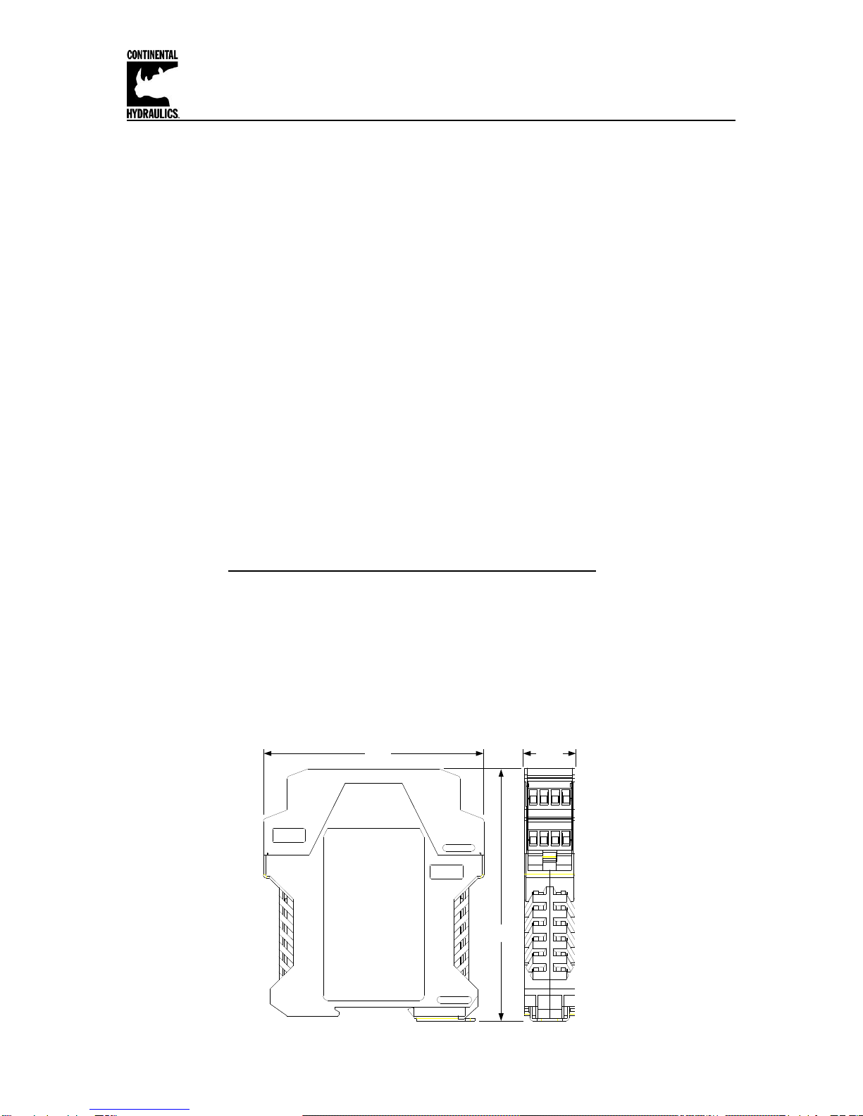
Dimensions …………………………………………….…………………………………………… 6
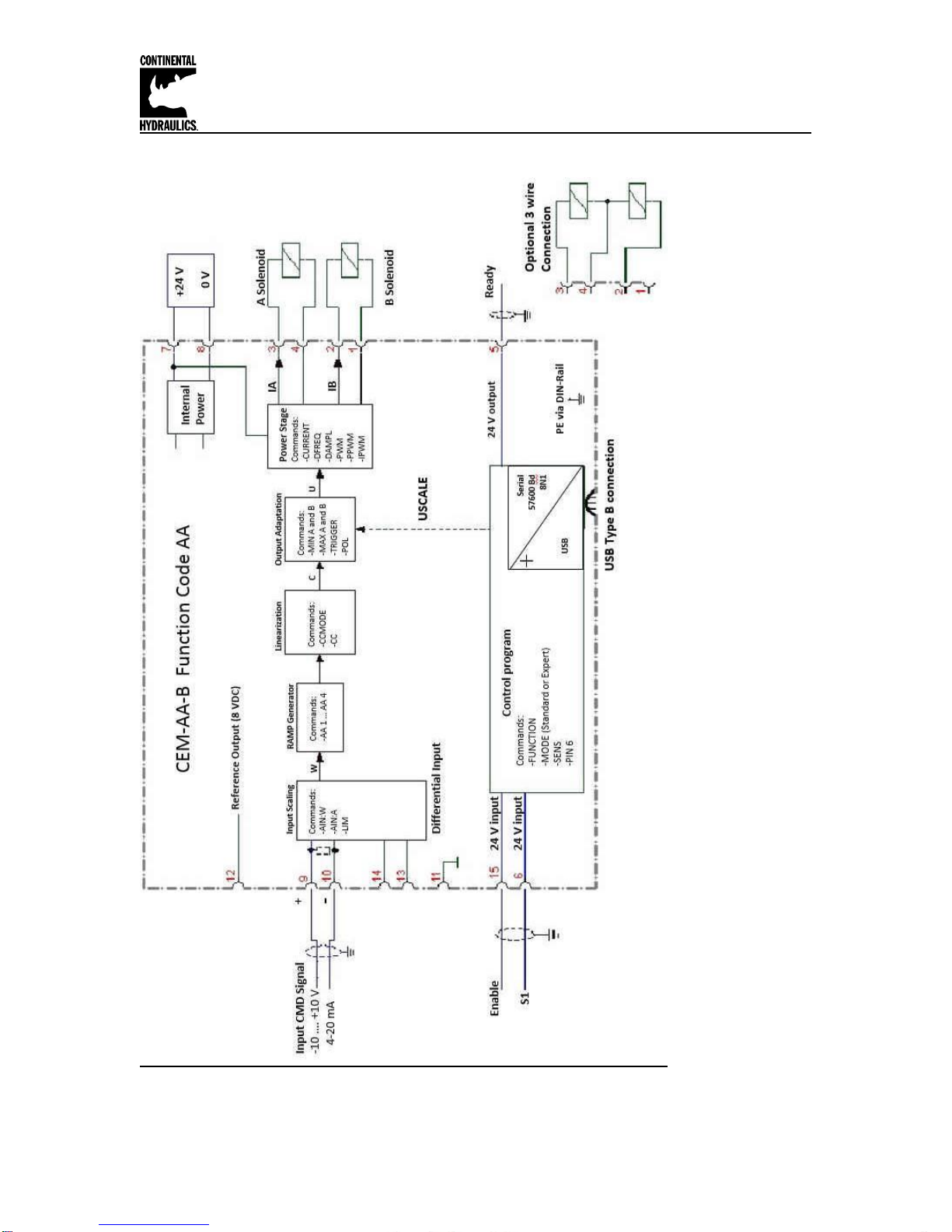
Circuit Diagram Function AA …………………………………………………………………... 7
Terminal Identification AA Function …………………………………………………………….. 8
Parameter List Function AA …………………………………………….………………….… 9
Circuit Diagram Function A-B …………………………………………………………………… 10
Terminal Identification A-B Function …………………………………………………………….. 11
Parameter List Function A-B ………………………………………………….……………… 12
Circuit Diagram Function RA …………………………………………………………………… 13
Terminal Identification RA Function …………………………………………………………….. 14
Parameter List Function RA ……………………………………………………….…………… 15
Command Parameter Descriptions
FUNCTION……………………………………………………………………………..… 16
LG (Language)…………………………………………………………………………… 16
MODE……………………………………………………………………………………... 16
SENS ……………………..……………………………………………………. ………... 17
CCMODE………………………………………………………………………………… 17
SOLENOIDS……………………………………………………………………………... 17
PIN:6………………………………………………………………………………………. 18
USCALE………………………………………………………………………………….. 18
ENABLE_B……………………………………………………………………………….. 18
LIM………………………………………………………………………………………… 19
POL……………………………………………………………………………………….. 20
AINA / AINB………………………………………………………………………………. 20
AIN………………………………………………………………………………………….21
AA:I / AB:I (RAMP Time)…………………………………………..………………….... 22
RMODE…………………………………………………………………………………… 23
S:0 –S:7………………………………………………………………………………….. 23
RA:0 –RA:7………………………………………………………………………………. 24
CCA / CCB……………………………………………………………………………..… 25
CC (Characteristics Linearization)…………………………………………………….. 26
MIN………………………………………………………………………………………... 27
MAX……………………………………………………………………………………... 27
TRIGGER………………………………………………………………………………... 27
CURRENT……………………………………………………………………………….. 29
DFREQ…………………………………………………………………………………… 29
DAMPL…………………………………………………………………………………… 29
PWM……………………………………………………………………………………… 30
ACC………………………………………………………………………………………. 30
PPWM / IPWM…………………………………………………………………………… 31
PROCESS DATA (Monitoring)…………………………………………………………………… 32
Failure Monitoring………………………………………………………………………………….. 33
Troubleshooting…………………………………………………………………………………….. 33

Continental Hydraulics Installation Manual
Page 3 of 33 CEM-AA-B CHI 1020611 01/2016
Technical Data - All Function Modes:
Power supply
[VDC]
12… 30 (incl. ripple)
Power consumption max.
[W]
60 (depending on type of solenoid, two solenoids are
active)
External fuse
[A]
3 medium time lag
Reference voltage
[V]
8 (maximum 25 mA)
Digital inputs
[V]
logic 0: < 2
[V]
logic 1: > 10
Input resistance
[kΩ]
25
Digital outputs
[V]
logic 0: < 2
[V]
logic 1: > 12 (50 mA)
Analogue inputs
[V]
±10 / 0… 10; 90 kΩ
[mA]
4...20; 390 Ω
Resolution
[%]
< 0.01
Nominal PWM output current
[mA]
500… 2600; broken wire monitored and short circuit
proof.
PWM frequency
[Hz]
61...2604; adjustable in steps
Sample time (process control)
[ms]
1
Sample time (solenoid current
control)
[ms]
0.125
Interface
USB type B
Virtual COM port driver (CHI-PC):
9600… 57600 Baud (Default = 57600),
1 Stop bit, No parity, No handshake
Housing
Snap On Module EN 50022
Polyamide PA 6.6
Combustibility class V0 (UL94)
Weight
[kg]
0.190
Protection class
IP20
Temperature range
[°C]
-20… 60
Storage temperature
[°C]
-20 …70
Humidity
[%]
<95 (not condensing)
Vibration
-
IEC 60068-2-6 (category C)
Connections
USB type B
4 x 4 pol. screw terminals
PE: direct via DIN rail
EMC
EN 61000-6-2: 8/2005
EN 61000-6-4: 6/2007 ; A1:2011

Continental Hydraulics Installation Manual
Page 4 of 33 CEM-AA-B CHI 1020611 01/2016
LED Indications - All Function Modes:
LED's Description of the LED function
1. Chasing light (over all LEDs): The bootloader is active.
No normal functions are possible.
2. All LEDs flash shortly every 6 s: An internal data error was
detected and corrected automatically! The module still works
regularly. To acknowledge the error the module has to have
power cycled.
Yellow + Yellow
Both yellow LEDs flash oppositely every 1 s: The nonvolatile
stored parameters are inconsistent! To acknowledge the error
the data has to be saved with the SAVE command or the
corresponding Function button in the CHI-PC program. If one of
the FUNCTION parameter is changed to an incorrect value, that
parameter value is deleted purposely, and set to default
values. In this case the LEDs indicate no error.
Identical to the READY output.
OFF: No power supply or ENABLE is not activated
ON: System is ready for operation
Flashing: Error detected (e. g. valve solenoid or 4… 20 mA).
Not active when SENS = OFF.
LED in the middle position = Current, Channel A; the intensity
is proportional to the output current
LED in the right position = Current, Channel B; the intensity is
proportional to the output current
GREEN + YELLOW
GREEN
YELLOW

Continental Hydraulics Installation Manual
Page 5 of 33 CEM-AA-B CHI 1020611 01/2016
Steps to install and configure a new application:
All parameters are adjusted using VEA-BUSB programming cable and CHI-PC Microsoft
Windows application.
1. Mount the module in a suitable location
2. Connect the power supply and valve solenoids
3. Down load and open the GUI program (www.continentalhydraulics.com/wp-
content/uploads/2015/01/setup-CEWMPC-10-v3.5.0.zip )
4. Connect to Laptop via USB to USB Type B communication cable.
5. Open the Options Tab and in setting, verify that the correct com port, full-Duplex and
57.6K Baud rates are selected.
6. Select Desired Function (AA / A-B / RA) for your application as desired, Click the ID
button to update the Parameter list.
7. Adjust current range to match valve
8. Adjust PWM / Dither to optimize performance of the valve
9. Adjust analog input to voltage or current, and scale input if required.
10. Adjust ramping (if desired)
11. Adjust internal monitor functions (if desired)
12. Adjust current output to the valve for the flow / pressure required (if desired)

Continental Hydraulics Installation Manual
Page 6 of 33 CEM-AA-B CHI 1020611 01/2016
Module Mounting Location:
This module is to be mounted in a cabinet for protection from the local environment.
Ensure there is adequate free space around the module to allow for cooling air flow.
This module is designed to snap onto an industry standard 35mm DIN rail.
Do not mount near other modules that emit high power electrical interference, such as motor
controllers and high power contactors.
Power Supply:
This module is designed to operate on DC power from a regulated power supply ranging from 12
to 30 volts. Match valve solenoid voltage rating to power supply, typically 12 or 24 volts.
A 3 amp medium action fuse is recommended in the “+” power supply line.
Wiring to Valve:
Two conductors are required for each solenoid. There is no need for shielding on these power
conductors.
Wire size is chosen to provide an acceptable voltage drop between the module and the valve
solenoid. The following chart is based on 5% drop for 12v and 24v applications. The listed cable
length is distance from module to valve, and includes the voltage drop of the return conductor.
Wire size 2.6A 12v 1.6A 24v 0.86A 24v
12 gauge 66 ft max 215 ft max 400 ft max
14 gauge 49 ft max 159 ft max 295 ft max
16 gauge 31 ft max 100 ft max 186 ft max
18 gauge 19 ft max 63 ft max 117 ft max
20 gauge 13 ft max 39 ft max 73 ft max
22 gauge 8 ft max 25 ft max 46 ft max
Dimensions:
4.5"
3.9" 0.9"

Continental Hydraulics Installation Manual
Page 7 of 33 CEM-AA-B CHI 1020611 01/2016
Circuit Diagram Function AA

Continental Hydraulics Installation Manual
Page 8 of 33 CEM-AA-B CHI 1020611 01/2016
Connection Supply
PIN 7 Power supply(see technical data)
0 V(GND) Power supply(ground).
Attention,PIN 8 and PIN 11 are connected internally. PIN 11 is used
as the GND potential for the command and feedback signals..
Connection Reference voltages output
PIN 12 Reference output voltage (8 V).
Connection PWM output
PIN 3 / 4 Current controlled PWMoutputs for solenoid A.
PIN 1 / 2 Current controlled PWMoutputs for solenoid B.
Connection Analogue input signals
PIN 9 / 10
Command (input) signal (W), range -100…100 % corresponds with -
10…10 V or 4…20 mA
0 Vreference for the signal inputs.
Attention,PIN 8 and PIN 11 are connected internally
Connection Digital inputs and outputs
Enable Input:
This digital input signal initializes the application.
The output and the READYsignal will be activated.
Bydeactivating, error signals are reset.
S1 input:
Function depends on parameter PIN:6 (USCALE/RAMP).
OFF: Output current depends on parameter USCALE; ramp
function is deactivated.
ON:Output current is not scaled byUSCALE, ramp function is
activated.
READYoutput:
ON: Module is ready,no errors are detected
OFF: ENABLE (PIN 15) is deactivated or an error is detected.
CEM-AA-B Function AA Input and Output Terminals
PIN 8
PIN 11
PIN 15
PIN 6
PIN 5

Continental Hydraulics Installation Manual
Page 9 of 33 CEM-AA-B CHI 1020611 01/2016
Parameter List Function AA
Ref Page
Command Parameter Help / Description STD EXP
16 FUNCTION AA Function mode (AA / A-B / RA) Press ID button after selection X X
16 LG EN EN English X X
16 MODE EXP Standard / Expert mode X X
17 SENS AUTO Malfunction monitoring [ON / OFF /AUTO] X X
17 CCMODE OFF Characteristics linearization [ON / OFF] X
18 PIN:6 USCALE Function of PIN 6 [USCALE / RAMP] X
18 USCALE 10000 Output current scale in 0.01% X
19 LIM 0 Range control input signal in 0.01% X
20 POL + Output polarity (+/-) X X
20 AINA V Input switching, voltage or current [V/C] (Voltage default) X
20 AIN:A 1000 1000 0 V Input scaling via linear equation X
22 AA:1 100 Ramptime acceleration A in ms X X
22 AA:2 100 Ramptime deceleration A in ms X X
22 AA:3 100 Ramptime acceleration B in ms X X
22 AA:4 100 Ramptime deceleration B in ms X X
26 CC characteristic curve Free definable characteristic linearization
27 MIN:A 0 Compensation of the Deadband in 0.01% X X
27 MIN:B 0 Compensation of the Deadband in 0.01% X X
27 MAX:A 10000 Output Scaling in 0.01% X X
27 MAX:B 10000 Output Scaling in 0.01% X X
27 TRIGGER 200 Trigger point of the MIN function in 0.01% X X
29 CURRENT 1000 Rated solenoid current 500…. 2600 mA X X
29 DAMPL 500 Dither amplitude in 0.01% of rated current X X
29 DFREQ 121 Dither frequency in Hz X X
30 PWM 2604 PWM frequency in Hz X
30 ACC ON Auto Adjustment of the current loop [OFF / ON] X
31 PPWM 7 P-Gain of the current loop X
31 IPWM 40 I-Gain of the current loop X
MODE

Continental Hydraulics Installation Manual
Page 10 of 33 CEM-AA-B CHI 1020611 01/2016
Circuit Diagram Function A-B

Continental Hydraulics Installation Manual
Page 11 of 33 CEM-AA-B CHI 1020611 01/2016
Connection Supply
PIN 7 Power supply(see technical data)
0 V(GND) Power supply(ground).
Attention,PIN 8 and PIN 11 are connected internally. PIN 11 is used
as the GND potential for the command and feedback signals.
Connection Reference voltages output
PIN 12 Reference output voltage (8 V)
Connection PWM output
PIN 3 / 4 Current controlled PWMoutputs for solenoid A
PIN 1 / 2 Current controlled PWMoutputs for solenoid B
Connection Analogue input signals
PIN 9 / 10
Command (input) signal A, range 0…100 % corresponds with 0…10 V
or 4…20 mA
PIN 13 / 14
Command (input) signal B, range 0…100 % corresponds with 0…10 V
or 4…20 mA
0 Vreference for the signal inputs.
Attention, PIN 8 and PIN 11 are connected internally
Connection Digital inputs and outputs
Enable Input Channel A/Bor Channel A (dependent on ENABLE_B):
This digital input signal initializes the application.
The output and the READYsignal will be activated.
Bydeactivating error signals are reset.
Enable Input Channel B (dependent on ENABLE_B):
This digital input signal initializes the application.
The output and the READYsignal will be activated.
Bydeactivating error signals are reset.
READYoutput:
ON:No internal or external errors are detected.
OFF:Both power stages are deactivated or an error is detected.
PIN 5
CEM-AA-B Function A-B Input and Output Terminals
PIN 8
PIN 11
PIN 15
PIN 6

Continental Hydraulics Installation Manual
Page 12 of 33 CEM-AA-B CHI 1020611 01/2016
Parameter List Function A-B
Ref Page
Command Parameter Help / Description STD EXP
16 FUNCTION A-B Function mode (AA / A-B / RA) Press ID button after selection X X
16 LG EN EN English X X
16 MODE EXP Standard / Expert mode X X
17 SENS AUTO Malfunction monitoring [ON / OFF /AUTO] X X
17 CCMODE OFF Characteristics linearization [ON / OFF] X
18 ENABLE-B OFF Separate enable signals [OFF / ON] x
19 LIM:A 0 Range control input signal in 0.01% X
19 LIM:B 0 Range control input signal in 0.01% X
20 POL:A 0 Output polarity (+/-) X X
20 POL:B + Output polarity (+/-) X X
20 AINA V Input switching, voltage or current [V/C] (Voltage default) X
22 AINB V Input switching, voltage or current [V/C] (Voltage default) X
21 AIN:A 1000 1000 0 V Input scaling via linear equation X
21 AIN:B 1000 1000 0 V Input scaling via linear equation X
22 AA:UP 100 Ramptime acceleration A in ms X X
22 AA:DOWN 100 Ramptime deceleration A in ms X X
22 AB:UP 100 Ramptime acceleration B in ms X X
22 AB:DOWN 100 Ramptime deceleration B in ms X X
25 CCA characteristic curve Free definable characteristic linearization X
25 CCB characteristic curve Free definable characteristic linearization X
27 MIN:A 0 Compensation of the Deadband in 0.01% X X
27 MIN:B 0 Compensation of the Deadband in 0.01% X X
27 MAX:A 10000 Output Scaling in 0.01% X X
27 MAX:B 10000 Output Scaling in 0.01% X X
27 TRIGGER 200 Trigger point of the MIN function in 0.01% X X
29 CURRENT:A 1000 Rated solenoid current 500…. 2600 mA X X
29 CURRENT:B 1000 Rated solenoid current 500…. 2600 mA X X
29 DAMPL:A 500 Dither amplitude in 0.01% of rated current X X
29 DAMPL:B 500 Dither amplitude in 0.01% of rated current X X
29 DFREQ:A 121 Dither frequency in Hz X X
29 DFREQ:B 121 Dither frequency in Hz X X
30 PWM:A 2604 PWM frequency in Hz X
30 PWM:B 2604 PWM frequency in Hz X
30 ACC ON Auto Adjustment of the current loop [OFF / ON] X
31 PPWM:A 7 P-Gain of the current loop X
31 PPWM:B 7 P-Gain of the current loop X
31 IPWM:A 40 I-Gain of the current loop X
31 IPWM:B 40 I-Gain of the current loop X
MODE

Continental Hydraulics Installation Manual
Page 13 of 33 CEM-AA-B CHI 1020611 01/2016
Circuit Diagram Function RA

Continental Hydraulics Installation Manual
Page 14 of 33 CEM-AA-B CHI 1020611 01/2016
Connection Supply
PIN 7 Power supply(see technical data)
0 V(GND) Power supply(ground).
Attention,PIN 8 and PIN 11 are connected internally. PIN 11 is used as
the GND potential for the command and feedback signals.
Connection Reference voltages output
PIN 12 Reference output voltage (8 V).
Connection PWM output
PIN 3 / 4 Current controlled PWMoutputs for solenoid A
PIN 1 / 2 Current controlled PWMoutputs for solenoid B.
Connection Analogue input signals
Digital gate inputs for selecting the command value:
PIN 6: S1 PIN 9: S2 PIN 14: S4
The whole range of set points can be chosen bybinarycoding of these
inputs.
0 Vreference for the signal inputs.
Attention,PIN 8 and PIN 11 are connected internally.
Connection Digital inputs and outputs
Enable Input:
This digital input signal initializes the application.
The output and the READYsignal will be activated.
Bydeactivating error signals are reset.
READYoutput:
ON:No internal or external errors are detected
OFF:ENABLE (PIN 15) is deactivated or an error is detected
PIN 15
PIN 5
CEM-AA-B Function RA Input and Output Terminals
PIN 8
PIN 6 / 9 / 14
PIN 11

Continental Hydraulics Installation Manual
Page 15 of 33 CEM-AA-B CHI 1020611 01/2016
Parameter List Function RA
Ref Page
Command Parameter Help / Description STD EXP-SD EXP-4Q
16 FUNCTION RA Function mode (AA / A-B / RA) Press ID button after selection X X X
16 LG EN EN English X X X
16 MODE EXP Standard / Expert mode X X X
17 SENS AUTO Malfunction monitoring [ON / OFF /AUTO] X X X
17 SOLENOIDS 2 Number of Solenoids X X X
23 RMODE SD Rampmode SD or 4Q X X X
23 S:0 0 Demand value related to the digital inputs in 0.01% X X X
23 S:1 0 Demand value related to the digital inputs in 0.01% X X X
23 S:2 0 Demand value related to the digital inputs in 0.01% X X X
23 S:3 0 Demand value related to the digital inputs in 0.01% X X X
23 S:4 0 Demand value related to the digital inputs in 0.01% X X X
23 S:5 0 Demand value related to the digital inputs in 0.01% X X X
23 S:6 0 Demand value related to the digital inputs in 0.01% X X X
23 S:7 0 Demand value related to the digital inputs in 0.01% X X X
24 RA:0 100 Ramptime related to the digital inputs in ms X X
24 RA:1 100 Ramptime related to the digital inputs in ms X X
24 RA:2 100 Ramptime related to the digital inputs in ms X X
24 RA:3 100 Ramptime related to the digital inputs in ms X X
24 RA:4 100 Ramptime related to the digital inputs in ms X X
24 RA:5 100 Ramptime related to the digital inputs in ms X X
24 RA:6 100 Ramptime related to the digital inputs in ms X X
24 RA:7 100 Ramptime related to the digital inputs in ms X X
22 AA:1 100 Ramptime acceleration A in ms X
22 AA:2 100 Ramptime deceleration A in ms X
22 AA:3 100 Ramptime acceleration B in ms X
22 AA:4 100 Ramptime deceleration B in ms X
26 CC characteristic curve Free definable characteristic linearization X X
27 MIN:A 0 Compensation of the Deadband in 0.01% X X X
27 MIN:B 0 Compensation of the Deadband in 0.01% X X X
27 MAX:A 10000 Output Scaling in 0.01% X X X
27 MAX:B 10000 Output Scaling in 0.01% X X X
27 TRIGGER 200 Trigger point of the MIN function in 0.01% X X X
29 CURRENT 1000 Rated solenoid current 500…. 2600 mA X X X
29 DAMPL 500 Dither amplitude in 0.01% of rated current X X X
29 DFREQ 121 Dither frequency in Hz X X X
30 PWM 2604 PWM frequency in Hz X X
30 ACC ON Auto Adjustment of the current loop [OFF / ON] X X
31 PPWM 7 P-Gain of the current loop X X
31 IPWM 40 I-Gain of the current loop X X
MODE

Continental Hydraulics Installation Manual
Page 16 of 33 CEM-AA-B CHI 1020611 01/2016
Parameter Descriptions
FUNCTION (Function mode)
Command
Parameters
Unit
Group
FUNCTION X
x= AA|A-B|RA
-
STD
The general Operating function of the module will be defined by this command.
AA: Functionality for directional valves with two solenoids and analogue input signals
A-B: Functionality for two pressure/throttle valves with analogue input signals
RA: Functionality for directional, pressure and throttle valves with pre-programmed values,
selectable by digital inputs.
After changing this parameter the ID-button has to be pressed in order to rebuild the parameter
table and a SAVE button has to be conducted.
LG (Changing the language for the help texts)
Command
Parameters
Unit
Group
LG X
x= EN English
DE German
-
STD
Either English or German can be selected for the help texts in the CHI-PC Microsoft Windows
application.
After making a change to the language settings, the parameter list has to be updated by pressing
the “ID” button.
MODE (Switching between parameter groups)
Command
Parameters
Unit
Group
MODE X
x= STD|EXP
-
STD
This command changes the parameter mode. Various commands (defined via STD/EXP) are
blanked out in standard mode. The several commands in expert mode have more significant
influence on the system performance. Therefore they should be changed with care.

Continental Hydraulics Installation Manual
Page 17 of 33 CEM-AA-B CHI 1020611 01/2016
SENS (Failure monitoring)
Command
Parameters
Unit
Group
SENS X
x= ON|OFF|AUTO
-
STD
This command is used to activate/deactivate the monitoring functions (4… 20 mA sensors, output
current, signal range and internal failures) of the module.
ON: All monitoring functions are active. Detected failures can be reset by deactivating the
ENABLE input. This mode should be used in case of active enabling and monitoring by
a PLC (READY signal).
OFF: No monitoring function is active.
AUTO: (Default Setting) Auto reset mode. All monitoring functions are active. If the failure
does not exist anymore, the module automatically resumes to work.
Normally the monitoring functions are always active because otherwise no errors are detectable
via the READY output. Deactivating is possible especially for troubleshooting.
AUTO MODE: The module checks each second the actual failure status, which will (in case of a
persistent error) trigger the LED and the READY output for a short time.
CCMODE (Activation of the characteristic linearization)
Command
Parameters
Unit
Group
FUNCTION
CCMODE X
x= ON|OFF
-
EXP
AA
A-B
This command will be used for activation or deactivation of the characteristics linearization (CC,
CCA and CCB). Through activating this parameter a simple and quick estimation of the
linearization is possible. (See pages 22 –23 for more details)
SOLENOIDS (One or two solenoids)
Command
Parameters
Unit
Group
FUNCTION
SOLENOIDS X
x= 1|2
-
STD
RA
This parameter allows you to adapt the amplifier to valves with one solenoid (e.g. pressure
valves) or with two solenoids (directional valves).

Continental Hydraulics Installation Manual
Page 18 of 33 CEM-AA-B CHI 1020611 01/2016
PIN:6 (Choice of the additional function of S1/PIN 6)
Command
Parameters
Unit
Group
FUNCTION
PIN:6 x
x= USCALE | RAMP
-
EXP
AA
This parameter defines the functionality of digital input PIN:6
USCALE: PIN 6 = active, USCALE will not scale the output.
PIN 6 = inactive, the output may be scaled by the USCALE parameter.
Ramps are active.
RAMP: PIN 6 = active, the internal ramp generator is activated.
PIN 6 = inactive, the internal ramp generator is deactivated.
USCALE is inactive.
USCALE (Output current scaling depending on PIN:6)
Command
Parameters
Unit
Group
FUNCTION
USCALE x
x= -10000… 10000
0.01 %
EXP
AA
If the parameter PIN:6 is set to USCALE and the digital input S1 (PIN 6) is off, this parameter
scales the output current. The default setting is 10000 (100 %) which does not change the output.
If USCALE is set to -10000 the polarity of the output will be flipped by switching the digital input
S1, which allows for controlling the module with a unipolar analogue signal.
If USCALE is set to 5000 the output of the Minimum and Maximum value will be reduced by 50%
with the same input command values.
ENABLE_B (Switching of the ENABLE Function)
Command
Parameters
Unit
Group
FUNCTION
ENABLE_B x
x= ON|OFF
-
EXP
A-B
The setting of this parameter activates independent enable signals for channel A and B. If set to
OFF, digital input PIN 15 enables both output channels. If set to ON, digital input PIN 15 enables
only channel A and digital input PIN 6 enables channel B. If only one solenoid is to be controlled,
ENABLE_B has to be set to ON and only the corresponding digital input has to be switched on.

Continental Hydraulics Installation Manual
Page 19 of 33 CEM-AA-B CHI 1020611 01/2016
LIM (Signal monitoring)
Command
Parameters
Unit
Group
FUNCTION
LIM:I X
i= A|B
x= 0… 2000
0.01%
EXP
A-B
LIM X
x= 0… 2000
0.01%
EXP
AA
The signal monitoring deactivates the output current and the READY output if the input signal
leaves the permitted range after scaling. This function makes it possible to detect a short circuit or
cable break of a joystick or potentiometer.
Example: LIM 500 (5% lower/upper limitation) If the input signal gets higher than 95 % or
lower than 5%, it leaves the permitted range and the outputs will switch off.
-100%
working
range
error range for
unipolar signals
error range for
bipolar signals
100%

Continental Hydraulics Installation Manual
Page 20 of 33 CEM-AA-B CHI 1020611 01/2016
POL (Output polarity)
Command
Parameters
Unit
Group
FUNCTION
POL:I X
i= A|B
x= +|-
-
STD
A-B
POL X
x= +|-
-
STD
AA
Valves with one solenoid:
This command allows a switch over of the output signal direction (after the MIN-MAX function).
Example: POL:A + Input signal 0… 100 %, nominal output current 0… 100 %.
POL:A - Input signal 0… 100 % nominal output current 100… 0 %.
Directional valves:
This command allows a switch over of the output polarity.
AINA (Current- / Voltage input)
AINB (Current- / Voltage input)
Command
Parameters
Unit
Group
FUNCTION
AINA X
AINB X
x=V|C
-
STD
AA
A-B
By the use of this command, the type of input signal may be chosen between voltage (0...10 V or
+/- 10 V) or current (4…20mA). If current is chosen, the shunt will be activated automatically.
AIN (Analogue input scaling)
Command
Parameters
Unit
Group
FUNCTION
AIN:I a b c x
i = A|B
a= -10000… 10000
b= -10000… 10000
c= -10000… 10000
x= V|C
-
-
-
0.01%
-
EXP
AA
A-B
Table of contents
Other Continental Hydraulics Amplifier manuals
Popular Amplifier manuals by other brands

Unison Research
Unison Research Unico 90 instruction manual

Pure Resonance Audio
Pure Resonance Audio DA2240 Installation and operation manual

Tektronix
Tektronix 7A18A instruction manual

Rocktron
Rocktron Velocity 100LTD user manual

Catalinbread
Catalinbread Epoch Pre EP-3 manual

Franklin
Franklin RA-10 Setup and user guide