Continental Hydraulics Installation Manual
Page 5 of 24 CEM-PA-B CHI 1020688 01/2016
14. Set the N_RANGE:X to the maximum pressure rating of the pressure sensor. For a 0-
210 bar pressure transducer, set N_RANGE:X to 210 bar. This setting should be the
same or greater than the SYS_RANGE value.
15. Use the OFFSET:X to compensate for the pressure transducer reading at actual 0bar
pressure.
16. Adjust RAMP as required.
17. Set internal monitor function, SENS, as required.
18. Adjust PID error correction parameters, (C:P, C:I, C:D, C:D_TI, C:FF), to tune the
system performance.
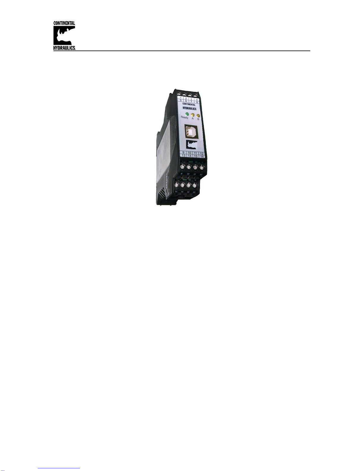
Module Mounting Location:
This module is to be mounted in a cabinet for protection from the local environment.
Ensure there is adequate free space around the module to allow for cooling air flow.
This module is designed to snap onto an industry standard 35mm DIN rail.
Do not mount near other modules that emit high power electrical interference, such as
motor controllers and high power contactors.
Power Supply:
This module is designed to operate on DC power from a regulated power supply ranging
from 12 to 30 volts. Match valve solenoid voltage rating to power supply, typically 12 or
24 volts. A 3 amp medium action fuse is recommended in the “+” power supply line.
Wiring to Valve:
Two conductors are required for each solenoid. There is no need for shielding on these
power conductors.
Wire size is chosen to provide an acceptable voltage drop between the module and the
valve solenoid. The following chart is based on 5% drop for 12v and 24v applications.
The listed cable length is distance from module to valve, and includes the voltage drop
of the return conductor.
Wire size 2.6A 12v 1.6A 24v 0.86A 24v
12 gauge 66 ft. max 215 ft. max 400 ft. max
14 gauge 49 ft. max 159 ft. max 295 ft. max
16 gauge 31 ft. max 100 ft. max 186 ft. max
18 gauge 19 ft. max 63 ft. max 117 ft. max
20 gauge 13 ft. max 39 ft. max 73 ft. max
22 gauge 8 ft. max 25 ft. max 46 ft. max
All analog input signal cables must be shielded!
Good analog system design requires that all analog signals in an electrically noisy
environment be shielded. Long wires act like antennas that pick up analog noise. The
wire connecting the analog command source to command this module must be shielded!
Shielding a noise sensitive wire is accomplished by wrapping a noise blocking foil or
braided shield around the signal wire. This shield must be grounded at only one end,
usually the end that sends the signal. A control cable may have many individual
conductors. The conductors may be shielded individually, or may be shielded as a
group. Short signal wires in electrically quiet environments may not need to be shielded.
The CEM family of modules all have an internal ground connection to the DIN rail. For
this module ground to be effective, please insure the DIN rail is properly grounded.