5935 W. 84th St. Suite A Indianapolis, Indiana 46278 (855) 423-2181 www.continu.us
With the CA-1000WIFI upgrade kit, the baseplate will come pre-installed on the RV.1)
Note: The CA-1000WIFI uses the same baseplate as the CA-1000 antenna that is installed by
the factory. If your RV does not have a CA-1000 antenna, please refer to the instructions on page
2 for installing a new CA-1000WIFI antenna baseplate.
U K I I
1) Detach the screws in the CA-1000 antenna, and disconnect all attached cables.
2) Take the CA-1000WIFI antenna head, and align it with the original baseplate.
Note: Dipole antenna’s need to face the back of the vehicle.
The CA-1000WIFI includes an additional CAT5 ethernet cable, and a 20 AWG Wi-Fi
reset cable. Insure that all cables are long enough to reach their destination points
inside the vehicle.
a)
3)
The optional ethernet connection will connect directly into the CWP-2000B
wall plate, for wired connections.
a) Option 1: (Recommended) Run the 20 AWG wire from the CA-1000WIFI to the
CWP-2000B Wall Plate inside the RV.
b) Option 2: The CA-1000WIFI-RS reset switch is an independent switch that can
be installed inside the RV, or placed in the opening between the CA-1000WIFI
antenna head and the baseplate.
5) Use the provided #8, 1/2” screws to secure the Antenna head to the base.
6) Re-apply sealant around the base mount if necessary.
4) The CA-1000WIFI Reset switch has two installation options.
With the CA-1000 baseplate already installed. You will begin by removing the old antenna.
U CA-1000WIFI
U K M I
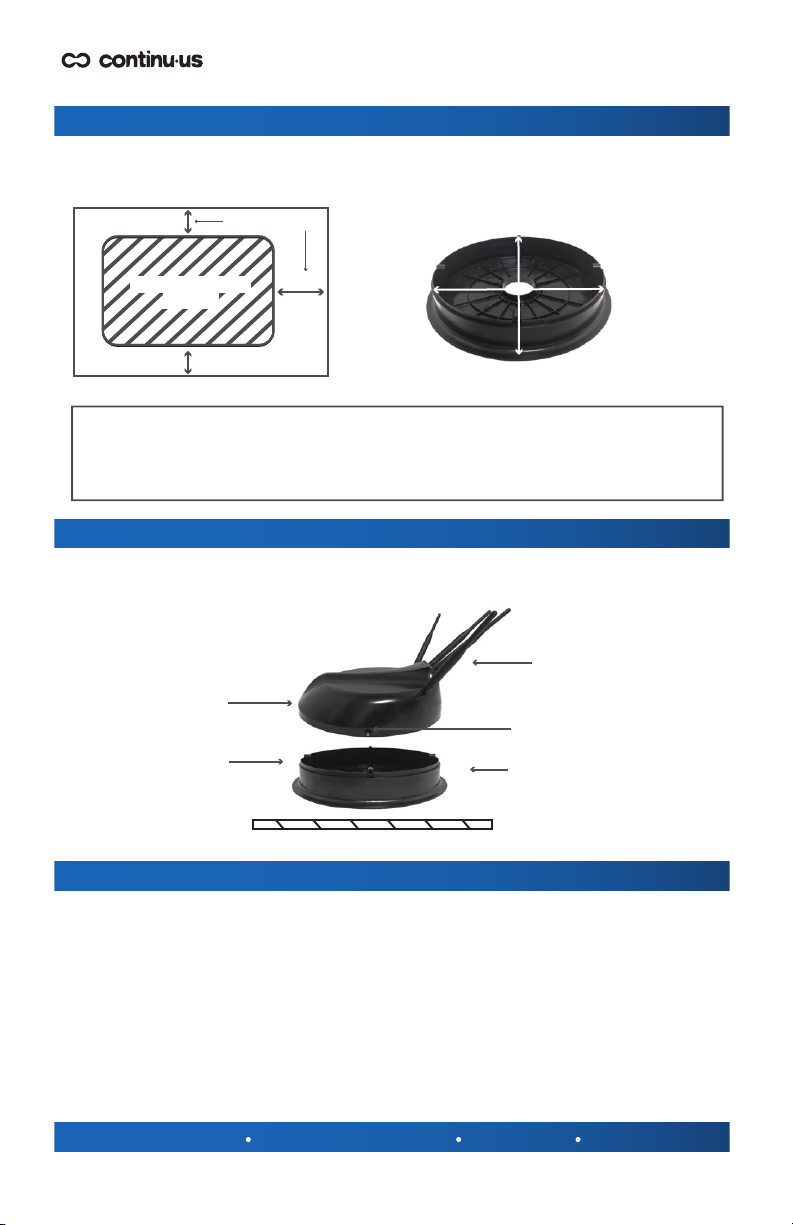
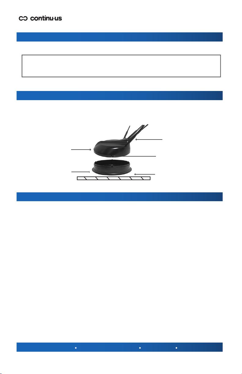
Antenna Head
Roof / Ceiling
Reapply Sealant if Necessary.
Existing Base Mount
Dipole antenna
#8, 1/2” Screws
Before installing CA-1000WIFI, it is recommended that you check with your vehicle
manufacturer for any special screw or installation requirements. Follow the assembly
diagram below (FIG 4.) to install your CA-1000WIFI.
FIG 4.