vii
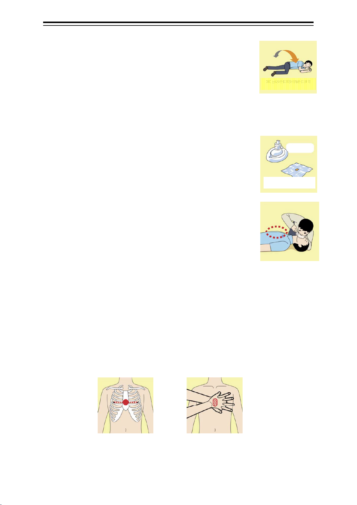
2) Perform chest compressions
• Perform uninterrupted chest compressions of 30
at the rate of about 100 times per minute.
While locking your elbows positioning yourself
vertically above your hands.
• With each compression, depress the chest wall to a depth of approximately 4 to 5 cm.
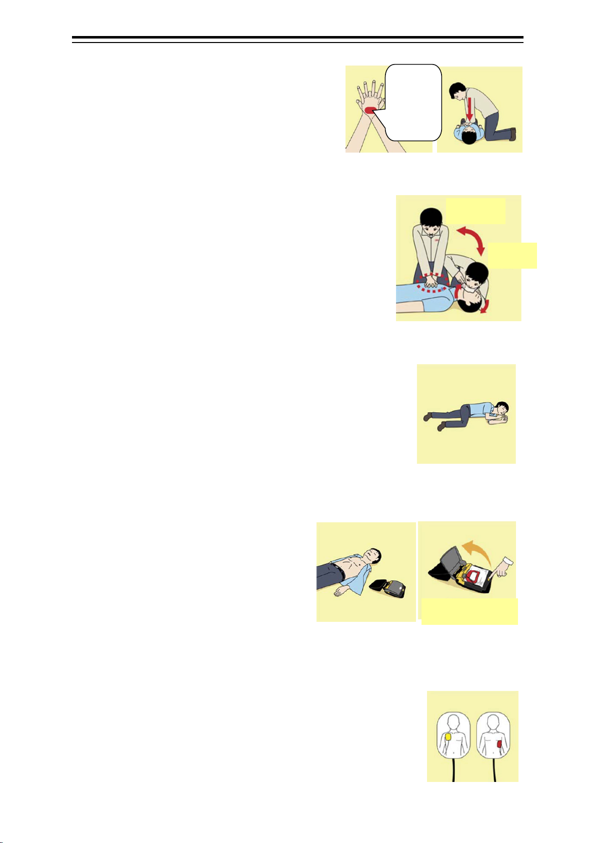
b) Combination of 30 chest compressions and 2rescue breaths
1) After performing 30 chest compressions, give 2rescue
breaths. If rescue breathing is omitted, perform only chest
compressions.
2) Continuously perform the combination of 30 chest
compressions and 2rescue breaths without interruption.
3) If there are two or more first-aiders, alternate with each other
approximately every two minutes (five cycles of
compressions and ventilations at a ratio of 30:2) without interruption.
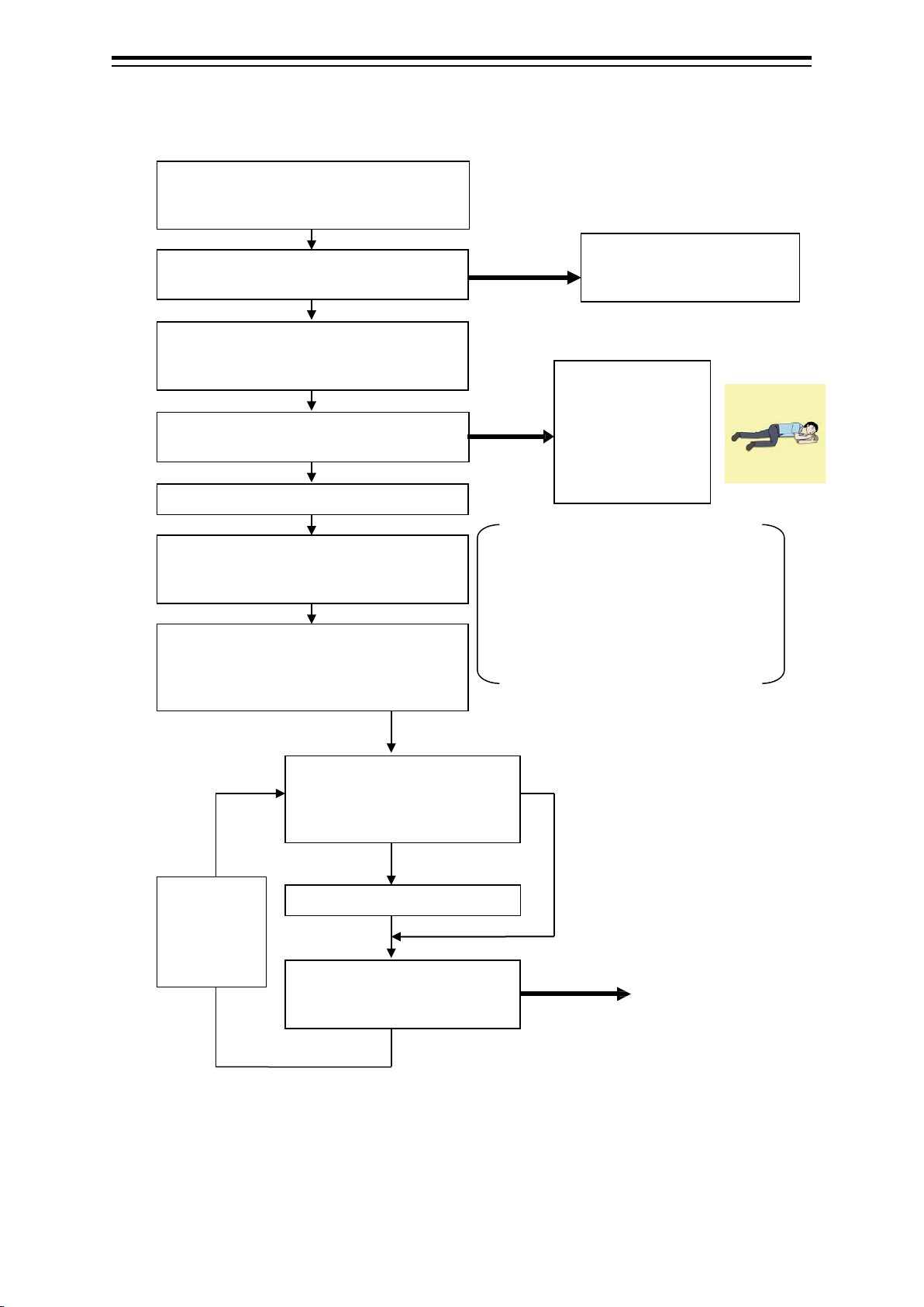
9. When to stop cardiopulmonary resuscitation (CPR)
a) When the injured or ill person has been handed over to the
emergency services
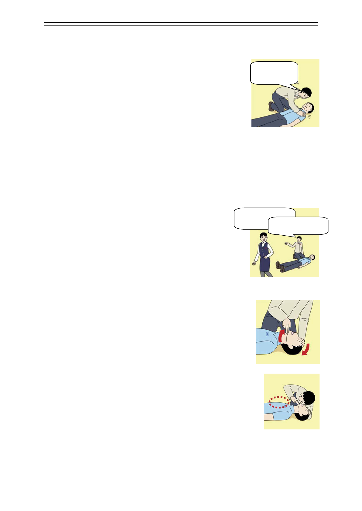
b) When the injured or ill person has started moaning or breathing
normally, lay him/her on his/her side in a recovery position and wait
for the arrival of emergency services.
10. Arrival and preparation of an AED
a) Place the AED at an easy-to-use position. If
there are multiple first-aiders, continue CPR
until the AED becomes ready.
b) Turn on the power to the AED unit.
Depending on the model of the AED, you
may have to push the power on button, or
the AED automatically turns on when you open the cover.
c) Follow the voice prompts of the AED.
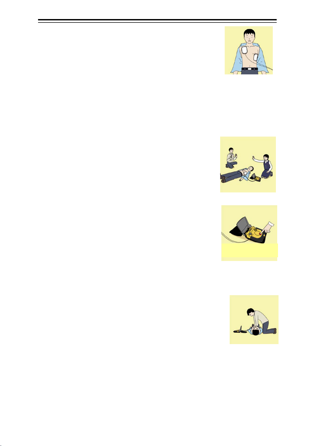
11. Attach the electrode pads to the injured or ill person's bare chest
a) Remove all clothing from the chest, abdomen, and arms.
b) Open the package of electrode pads, peel the pads off and securely
place them on the chest of the injured or ill person, with the adhesive
side facing the chest. If the pads are not securely attached to the chest,
the AED may not function. Paste the pads exactly at the positions
indicated on the pads, If the chest is wet with water, wipe dry with a dry towel and the like, and
30 times
with these
parts (the
heels of
both
hands).
2 times
Turn on the power.