CONTRASTECH PLU Series User manual

PLU Series Controller
USER’S MANUAL FOR VT-LT2-PLU2460-4
Version: 1707 Language: 000 (English)
Release Date: February 2017

2
Introduction
Please read the manual carefully before using the controller. And please keep it for future use.
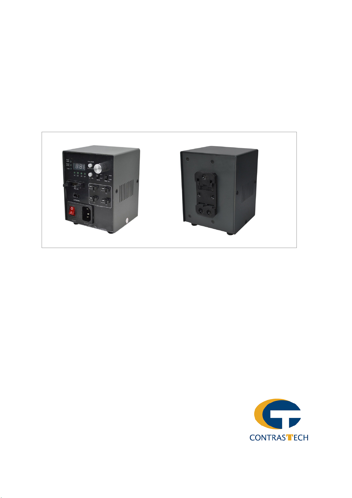
This controller can increase the brightness of normal 24V LED light by 3-4 times. It’s mainly used to control ma-
chine vision and industrial inspection LED light source.
1Features:
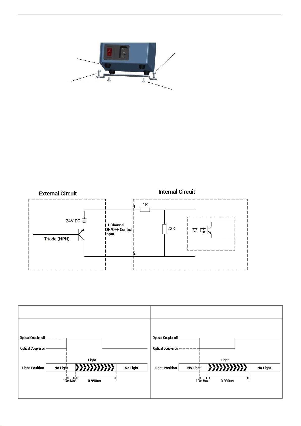
• Internal and external trigger input. High and low electrical levels can be used flexibly.
• For circuits control by individual, can set the lighting time from 10 to 990uS.
• Power cut memory, setting loch, fault detection, warning function.
• The lighting time and percentage can be manually controller by the knob on the front panel, and can also
be externally controller by PLC or machine vision devices.
• Control the lighting time precisely.
• Fast trigger response time.
• Be applicable to every 24V power input LED light source, 48V output, 60W total power consumption.
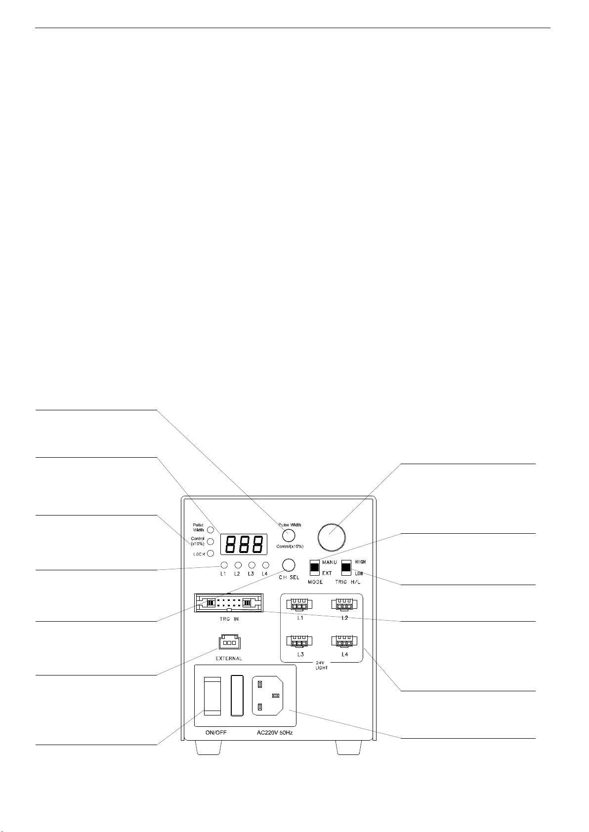
2 Panel Description
Mode switch
Digital display
Function indicators
Channel Indicators
Channel switch
RS232-port
AC power input switch
Pulse width: Lighting time adjust mode
Control (X%): Pulse width adjust mode
Lighting time display(10-990uS)
Pulse width display(10-100%)
Pulse width: light time adjust mode
Control (x10%): Pulse width set mode
LOCK: interface control locked
L1-L4 channel setting switch display
Function 1: L1~L4 setting select switch
Function 2: Long press 2S, Manual setting
interface locked
PC control communication port
Adjust Knob
Function 1: Light time adjust(10-990uS)
Function 2: Pulse width adjust(10~100%)
INT: Internal trigger mode
EXT: External trigger mode
Internal/External trigger switch
Trigger signal high and low level switch
External trigger connecting port(10-pin)
Output DC48V(1pin positive, 3Pins negative)
Trigger signal mode switch
Output port
AC power input receptacle
AC100~240V/50~60Hz
USER’S MANUAL FOR VT-LT2-PLU2460-4

3
3 Specification
Model VT-LT2-PLU2460-4
Channels 4
Error Detected Display Front digital display
Input Voltage (Rated) AC100V~240V
Trigger Function Yes
Trigger Input Voltage 5~24V DC
Output Power (Rated) 4 channels in total: 60W Max
Output Voltage (Rated) DC 48V
Output Current (Rated) One Channel: 5A Max
Lighting Delay 10 us Max
Operating Environment Temperature: 0 to 40°C, Humidity: 20% to 85% RH (with no condensation)
Storage Environment Temperature:-20 to 40°C, Humidity: 20% to 85% RH (with no condensation)
Cooling Method Air cooling
Surface Treatment SPCC surface spray treatment
Weight 1KG
Standard Accessories Trigger cable/ AC cable
Optional Accessories RS-232 communication cable(3m), RS232 to USB cable
Over-current Protection Activated when output current overload 7% or higher (OCP displayed), reset by reopen-
ing the power supply.
Trigger I/O MIL connector 10PIN
External Control Connector
Pulse width/ Lighting time setting E-CON connector
4Serial Port Communication Protocol
4.1 Communication Arguments
Protocol Working Mode Rate Transport Format
RS-232 Half-duplex Start Bit Data Bits Check Bit Stop Bit
19200bps 1801
4.2 Communication Format
Identifier
(0x40)
Length
LEN
Device
CODE
Device
ID Command 1 Command... Check
CHKSUM
4.3 Note
• The control pack is made up of identifier, device Code, device ID, Command group and check SUM in turn.
• A command group can be made up of one or several commands, but at least one.
• One command is usually made by command code, channel No. and command data, but to some com-
mand, it may not have channel No. or command data.
• The control pack length is the bytes of device Code, device ID and all the commands, that is the bytes be-
tween length and check SUM.
USER’S MANUAL FOR VT-LT2-PLU2460-4

4
4.4 Command Group
Device Code:
0x02
Command
Code
Channel
No. Command Data Notes
1ID Setting 0x09 0~99
2Time Setting 0x1A 0~3 0~99 N*10us
3% Setting 0x22 0~3 1~10 N*10%
4Read PARM 0x31x 0~3
5
Device reply 1
Channel PARM 0x5A Time % Device reply 1 channel parameter.
Device reply 4
Channels PARM 0x60 Time % Device reply all 4 channels parameter..
6Reply correct 0x00 All commands of the control pack is correct.
7Reply incorrect 0x01 Exist incorrect commands or parameters.Error Code
4.5 Output Channels
Channel L1 L2 L3 L4
Setting 00 01 02 03
4.6 Examples
●Set time of L1 as 10 μs
Identifier Length Device
CODE
Device
ID
Commands
Checksum
Time
Setting
Channel
No. Time
(0x40) 0x05 0x02 0x00 0x1A 0x00 0x01 0x62
Command Rollback: 0x40, 0x03, 0x03, 0x00, 0x00, 0x44
• The check SUM is the sum of the bytes of identifier, length, device Code, device ID and all the commands.
• If the device ID of the control pack is 0xFF, it means that the command works on all the devices of all the
device ID. Or it only works on the device with the same device ID.
• If the Channel No. of the command is 0xFF, it means that the command works on all the channels of that
device. Or it only works on the specific channel.
• Only when the device receives the complete control pack and the check SUM is correct, will the device
deal with its command and make corresponding reply.
• Device will only make one reply even though there is number of commands in a control pack.
• Device reply correctly when all the commands of the control pack is correct; Reply incorrect for wrong
commands or data; No treatment for unrecognized commands.
• When the device ID is 0xFF, it means that this control pack is broadcast control pack. The device will
make corresponding treatment but no reply.
• The above device refers to every series control unit, for example this series is 02.
USER’S MANUAL FOR VT-LT2-PLU2460-4

5
●Set L1 as10%, time of L2 50 μs, L3 30%
Identifier Length Device
CODE
Device
ID
Command
Checksum
%
Setting
Channel
No. %
(0x40) 0x05 0x02 0x00 0x22 0x00 0x0A 0x73
●Set L1 is 100%
Identifier Length Device
CODE
Device
ID
Commands
Check-
sum
%
Setting
Channel
No. %Time
Setting
Channel
No. Time %
Setting
Channel
No. %
(0x40) 0x0B 0x02 0x00 0x22 0x00 0x01 0x1A 0x01 0x05 0x22 0x02 0x03 0xB7
●Set all channels as 10%, time as 50 μs
Identifier Length Device
CODE
Device
ID
Commands
Checksum
%
Setting
Channel
No. %Time
Setting
Channel
No. Time
(0x40) 0x08 0x02 0x00 0x22 0xFF 0x01 0x1A 0xFF 0x05 0x8A
●Read device parameters of all channels ●Read device parameter of L1 Channel
Identifier Length Device
CODE
Device
ID
Command
Check-
sum
Read
PAPM
Channel
No.
(0x40) 0x04 0x02 0x00 0x31 0xFF 0x76
Identifier Length Device
CODE
Device
ID
Command
Check-
sum
Read
PAPM
Channel
No.
(0x40) 0x04 0x02 0x00 0x31 0x00 0x77
●Change the Controller ID to 01
Identifier Length Device
CODE
Device
ID
Command
Check-
sum
Read
PAPM
Channel
No.
(0x40) 0x04 0x02 0x00 0x09 0x01 0x50
Identifier Length Device
CODE
Device
ID
Commands
Check-
sum
Time
Setting
Channel
No. Time Time
Setting
Channel
No. Time Time
Setting
Channel
No. Time Time
Setting
Channel
No. Time
(0x40) 0x0E 0x02 0x00 0x1A 0x00 0x01 0x1A 0x01 0x02 0x1A 0x02 0x03 0x1A 0x03 0x04 0xC8
●Set time of L1 as 10 μs, L2 as 20 μs,L3 as 30 μs,L4 as 40 μs
USER’S MANUAL FOR VT-LT2-PLU2460-4

6
NO Signal Color
1Channel 1 Anode Brown
Cathode Orange
2Channel 1 Anode Yellow
Cathode Black
3Channel 1 Anode Blue
Cathode Green
4Channel 1 Anode Purple
Cathode Grey
Output
5V/200mA
Anode White5
Cathode Red
3000
5 Dia
One end cut
3000mm
123
5 Accessories Dimension and User Munual
5.1 External Trigger — Standard
●External Trigger Input Connector
●External Trigger Input Wire Dimension (mm)
●Installation Method
Installation: Plug the connector into
the receptacle.
Uninstallation: Unlock and then pull
out the connector.
5.1 RS232 Communication Cable — Standard
●Controller Side RS232 Communication Connector Definition
●RS232 Communication Cable Dimension (mm)
USER’S MANUAL FOR VT-LT2-PLU2460-4

7
●Installation Method
Installation: Plug the connector into
the receptacle.
Uninstallation: Unlock and then pull
out the connector.
6 DIN Guide Rail Installation
Installation: Lock the panel of controller to the DIN
rail, and push down the controller as direction 1 and
2 at the same time.
Uninstallation: Push down the controller as direc-
tion 3 and then pull it out as direction4.
Mounting Bracket — Optional
●Dimension (mm)
USER’S MANUAL FOR VT-LT2-PLU2460-4

8
●Mount Bracket Installation
Screws for securing the bracket to the suface
(Choosing a right type screw by your own demands)
M3 Screws for mount bracket (included)
M4 screw for fixed MATS
Rubber Feet Pad
Installation:
1. Take down the rubber feet pat from the bottom of the controller, then take down the screws of the rubber feet pad by screw-
driver.
2. Fix the bracket to the base by four screws of the bracket.
3. Fix the controller to a right place by screws. (The screws are not provided.)
7Trigger Signal Application Guide
7.1 Schematic Diagram
7.2 Trigger Input Working Drawing
USER’S MANUAL FOR VT-LT2-PLU2460-4
Adjust the trigger signal mode to HIGH Adjust the trigger signal mode to LOW
Trigger signal rising edge light up
LED Lighting time = Setting Time * Percentage
Trigger signal falling edge light up
LED Lighting time = Setting Time * Percentage

9
DIN
Guide rail
88
(8) (13)
96
69 59
120
(7)
8 Shell Dimension (mm)
For more information please contact our sales or visit our website
at http://www.contrastech.com
Specifications subject to change without notice.
No.11, Xiyuan 8th Road West Lake District, Hangzhou 310030 China
USER’S MANUAL FOR VT-LT2-PLU2460-4
This manual suits for next models
1
Table of contents