Contrec 220 User manual

LEVEL MONITOR
MODEL 220
June 2017
220-M-V3.1


CONTENTS
1. Introduction 1
1.1 Model Number Designation 2
1.2 Intrinsic Safety Approvals 3
2. Specification 4
3. Operation 6
3.1 Display 6
3.1.1 Level Bar Graph 6
3.1.2 Contents 7
3.2 Front Panel Operation 8
3.2.1 Displaying Data 8
3.2.2 Changing Data 11
3.2.3 Timeout Condition 12
3.3 Test Mode 12
3.4 Alarms 13
3.4.1 Types of Alarms 14
3.4.2 Alarm Deadband 15
3.4.3 Alarm Action 15
3.4.4 Setting Alarms 17
3.5 Non-Linearity 18
3.6 Filtering 22
3.7 Density Correction 24
4. Programming 26
4.1 Program Steps 27
5. Signal Input 30
6. Alarm Outputs 31

7. Installation 33
7.1 Wall Mounting 33
7.2 Panel Mount Version 34
7.3 Removing the Front Panel 35
7.4 The Main Electronics 37
7.5 Wiring 38
7.6 Maintenance 38
7.7 Terminal Designations 39
8. Intrinsic Safety Connections 40
Index 42

Introduction 1
1. INTRODUCTION
The Model 220i Level Monitor is a microprocessor based instrument
which accepts a 4-20mA input and displays level and contents. It is
powered entirely from the 4-20mA loop and, therefore, does not require
an external power source.
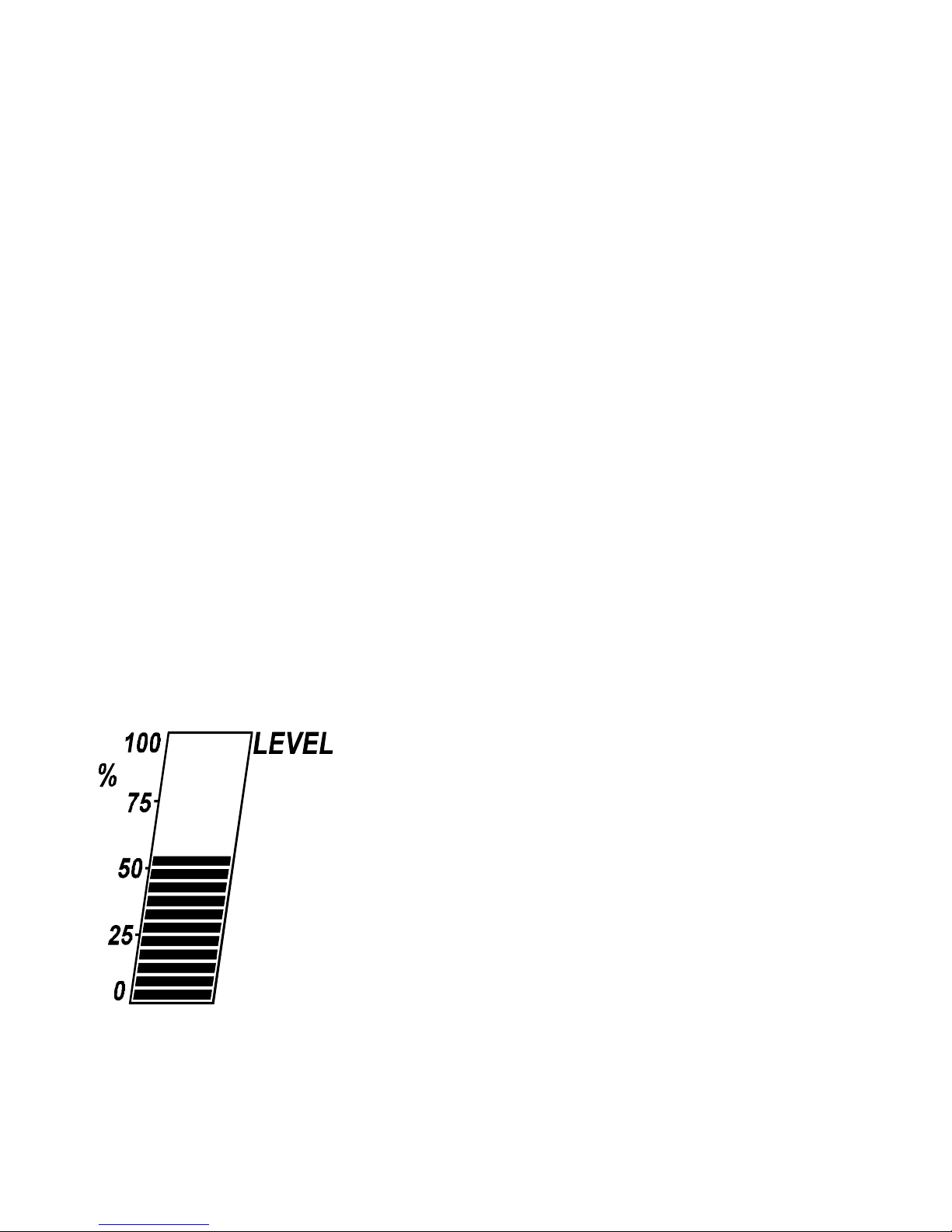
Level is displayed in a bar graph as 0...100%. The contents are a 7 digit
numeric display which can be spanned in any engineering units.
The instrument is fully programmable; the user can program alarm settings,
span & zero levels and non-linear correction points. Calculation constants are
also set from the front panel and are stored in a non-volatile memory which
retains data indefinitely.
The Model 220i Rate Totaliser conforms to the EMC-Directive of the Council of
European Communities 2004/108/EC, the LVD directive 2006/95/EC and the
following standards:
EN61326:2013 Electrical equipment for measurement, control
and laboratory use – EMC requirements :
Residential, Commercial & Light Industry
Environment & Industrial Environment.
EN61010:2010 Safety requirements for electrical equipment
for measurement, control, and laboratory use.
In order to comply with these standards, the wiring instructions in Section 7.5
must be adhered to.

Introduction
2
1.1 MODEL NUMBER DESIGNATION
The Model Number of the 220i describes the input and output options installed
and the mounting options.
220 i . 2 M
Model Mounting
220i Intrinsically Safe 1Panel mount
version 2Wall mount
62" pipe bracket
Approvals
CCSA USA/Canada approval
MATEX/IECEx approval
Tank Conversion Software
220CSW

Introduction 3
1.2 INTRINSIC SAFETY APPROVALS
The Model 220i is certified for use in hazardous areas and has IECEx, ATEX
and CSA US/C approvals.
The Model 220i certification details are:
IECEx Approval IECEx BVS 15.0099X
Rating Ex ia IIB T4 Gb
ATEX Approval BVS 15 ATEX E 106 X
Rating II 2G EX ia IIB T4 Gb
Ambient Temperature: Maximum ambient temperature of 60°C.
CSA US/C Approval LR 104 840-5.
Type: Class 1, Groups C and D.
When installing in hazardous areas, the instrument will have to be
installed according to the guidelines given in Section 9 and in
accordance with standards for wiring and installation in hazardous
areas.
4-20mA Input
The input can be connected to IS circuits with the following maximum
values:
Ui = 28V
Ii = 93mA
Pi = 653mW
Relay Outputs
The outputs can be connected to IS circuits with the following
maximum
values:
Ui = 28V
Ii = 93mA
Pi = 653mW

Specification
4
2. SPECIFICATION
General
Display: Continuously powered LCD.
Level: 30mm bar graph.
Level Span: 0...100% per full scale.
Contents: 7 digit with 4½ digit resolution, 12mm (0.5") high.
Contents Span: The units of measure (eg. litres) at full scale
of input signal. The contents span is
programmable in the range of 0.000...9,999,999.
Volume: Either "Volume" or "Contents" can be
displayed.
This is user programmable.
Decimal Points: Decimal point positions for contents
is programmable in range of 0...3
decimal points.
Signal Type: 4-20mA.
4-20mA
Resolution and Linearity: 0.05% of span.
Accuracy: 0.05% of span @ 25°C.
0.1% (typically) of span full temperature range.
Update Time: 0.5 second.
Connection: 2 wire.
Voltage Drop: 2.5V maximum.
Outputs
Type: 4 open collector output alarms suitable for
driving dc solenoids or external relays. The
outputs
provide:
1. high-high.
2. high.
3. low.
4. low-low.
Switching Power: 200mA. 30Vdc maximum.
Saturation Voltage: 0.8Vdc across the output in the "on" state.
Isolation: All outputs are separately opto-isolated.

Specification 5
Physical
Operating Temperature: -20°C to 60°C.
Dimensions: 97mm (3.8") high x 150mm (5.9") wide x
41mm (1.6") deep (not including cable glands).
Protection: Nema 4X or IP67 standards.
Cable Entry: Cable glands.
Mounting: Universal mounting bracket is supplied as
standard.
Pipe Mounting: A galvanised metal bracket is available which
enables the instrument to be mounted on a
2"horizontal or vertical pipe.

Operation
6
3. OPERATION
The Model 220i Level Monitor accepts a 4-20mA input signal from a level
sensor such as a pressure transmitter, ultrasonic sensor or capacitance probe.
The instrument is powered entirely from the loop and, therefore, requires no
external power or internal batteries.
The instrument is fully programmable with all operating parameters
and calculation constants programmable from the front panel (see
Section 4.1). The setup parameters are stored in a non-volatile
memory and are retained for at least 10 years in the event of a
power loss.
3.1 DISPLAY
The display of the Model 220i comprises of:
Level Bar Graph
Contents
3.1.1 Level Bar Graph
The level bar graph displays the vertical level
of liquid as a percentage.
Inputs of 4mA and 20mA can be programmed
to correspond to 0% and 100% respectively, or
can be inverted so that 4mA will correspond to
100% and 20mA will correspond to 0%.
Note that the level is corrected for density
(if applicable) as described in Section 3.7.

Operation 7
3.1.2 Contents
The contents is a 7 digit numeric display where the span can be
programmed during setup to read in any engineering units. The contents
are displayed with 4½ resolution in respect to the maximum contents.
For example, if the maximum contents is 1234567, the display will show up
to 5 digits plus trailing zeros. At different inputs the following will be
displayed:
1234567 will be displayed as 1234500; 234567 will be displayed as 2345000.
However, if the first digit is greater than 1, then up to 4 digits only will
be displayed with trailing zeros. For example, if the maximum contents is
2345678, then at different inputs:
2345678 will be displayed as 2345000; 345678 will be displayed as 345000.
CALCULATION OF CONTENTS
For a linear tank the contents is calculated as follows:
Contents = (Span) x (% Level) + Offset
Transmitter
OFFSET
% LEVEL
SPAN
Zero
Contents

Operation
8
3.2 FRONT PANEL OPERATION
3.2.1 Displaying Data
The alarm setpoints and density correction factor can be viewed by pressing
the DISPLAY key.
Key action What you will see What this means
If there are flashing alarms on
the display they will stop
flashing.
Acknowledges alarms if
alarms are flashing on
the display.
High-high alarm.
The value of the high-high
alarm.
The high-high alarm
setpoint as a % of
maximum level or
contents value.
High alarm.
AL-HH
AL-HI
DISPLAY
DISPLAY
DISPLAY
DISPLAY

Operation 9
Key action What you will see What this
The value of the high alarm.
The high alarm setpoint
as a % of maximum level
or contents value.
Low alarm.
The value of the low alarm.
The low alarm setpoint
as a % of maximum level
of contents value.
Low-low alarm.
The value of the low-low
alarm.
The low alarm setpoint
as a % of maximum level
or contents value.
AL-LO
AL-LL
DISPLAY
DISPLAY
DISPLAY
DISPLAY
DISPLAY

Operation
10
Key action What you will see What this
Density correction
The value of the density
correction factor.
A factor for those
applications where the
density of the fluid in
the tank is likely to
change (default of
1.000).
Returns to contents display.
DISPLAY
DISPLAY
DISPLAY
dc

Operation 11
3.2.2 Changing Data
Each of the above parameters can be changed as follows:
1. Pressing the DISPLAY key consecutively until the numeric value of the
parameter to be changed appears (as described in the previous diagram).
2. This value can then be changed using the following keys:
This key steps from digit to digit, causing the
digit to flash. Only flashing digits can be
changed.
This key increments the flashing digit.
Example.
To change the high alarm setpoint to 75:
1. Press DISPLAY until the value of the high alarm appears. This will be
the value after AL-HI.
2. The first digit is flashing, this means it can be changed. Using
the key, this digit is changed to 7.
3. The key is pressed so that the second digit flashes.
4. Using the key, this digit is changed to 5.
Note that the Model 220i can be programmed so that the above parameters
cannot be changed, see Section 4.1.

Operation
12
3.2.3 Timeout Condition
Upon entering the display mode, if no key is pressed for 10 seconds, the
display returns to the contents display with alarm acknowledgment cleared.
3.3 TEST MODE
The 220i has a test mode which can be entered by simultaneously pressing
all 3 front panel keys. There are 3 tests:
Low Test By pressing the key, the low and low-low
alarms outputs will be energised.
High Test By pressing the key, the high and high-high
alarm outputs will be energised.
Display Test By pressing the DISPLAY key, all segments of the
display will flash.
To exit the test mode all three keys are pressed simultaneously.

Operation 13
3.4 ALARMS
The Model 220i has 4 alarm outputs:
The alarms can be assigned to level or contents which is done
during programming (see Section 4.1). Each alarm is individually
programmed as a percentage (0-100%) of level or contents.
All of the alarms have open collector outputs and are separately isolated via
opto-isolators. The outputs are internally protected against voltage spikes
caused by relays and coils.
High-High (HH)
High (H)
Low (L)
Low-Low (LL)

Operation
14
3.4.1 Types of Alarms
3.4.1.1 Alarm Output
The Model 220i can be programmed for the alarm outputs to operate in one of
two ways:
1. the alarm outputs can energise (switch on) during an alarm condition, or
2. the alarm outputs can de-energise (switch off) during an alarm condition.
3.4.1.2 High Alarms
The high alarms will be activated when the contents or level in the tank
increase above the high alarm setpoints. These alarms will be deactivated
when the contents or level falls below these programmed setpoints.
When setting the alarms, the high-high alarm should be set higher than the
high alarm.
3.4.1.3 Low Alarms
The low alarms will be activated when the level or contents in the tank falls
below the low alarm setpoints. These alarms will be deactivated when the
level exceeds the programmed setpoint.
Similarly, when setting the low alarms, the low-low alarm should be set below
the low alarm.

Operation 15
3.4.2 Alarm Deadband
To prevent an alarm toggling on and off when the level is close to the
setpoint, a user programmable deadband is provided. The deadband is a
percentage (0-100%) of the maximum level or contents.
Example 1.
If the low alarm is set to 20% and the deadband is set to 5%, the alarm will
be activated when the level reaches 20%. The alarm will then stay
activated until the level increases above 25%.
Example 2.
If the high alarm and deadband are set at 80% and 5% respectively, the
alarm will be activated at 80% and will stay activated until the level falls
below 75%.
3.4.3 Alarm Action
When an alarm condition exists the Model 220i will act in the following way:
1. The appropriate alarm output will be activated.
2. The display will flash the name of the alarm.
3. In some cases these alarms may be acknowledged from the front
panel.
This will depend on whether they are programmed as continuous
or acknowledgeable alarms. This is set up during programming
(see Section 4.1).
The differences between acknowledging continuous and acknowledgeable
alarms are described in table on the following page.

Operation
16
Acknowledgeable Alarms Continuous Alarms
1. These alarms are acknowledged
by pressing the DISPLAY key.
1. A continuous alarm cannot be
acknowledged.
2. Once the alarm is acknowledged
the flashing on the LCD will
cease, with the alarm message
remaining solid. The message
will remain on the screen until
the alarm condition no longer
exists.
2. The flashing on the LCD cannot
be stopped and will keep
flashing until the alarm
condition no longer exists.
3. Once the alarm is
acknowledged,the alarm
output will be deactivated.
3. The alarms will only be
deactivated when the level
(or contents) is outside
alarm conditions.
Note that acknowledging the
LL alarm will also acknowledge
(and deactivate) the L alarm.
Similarly, acknowledging the HH
alarm will also acknowledge
(and deactivate) the H alarm.
Table of contents
Other Contrec Monitor manuals