manuals.online logo
Brands
  1. Home
  2. •
  3. Brands
  4. •
  5. Contro l4
  6. •
  7. Controllers
  8. •
  9. Contro l4 HC-300 User manual

Contro l4 HC-300 User manual

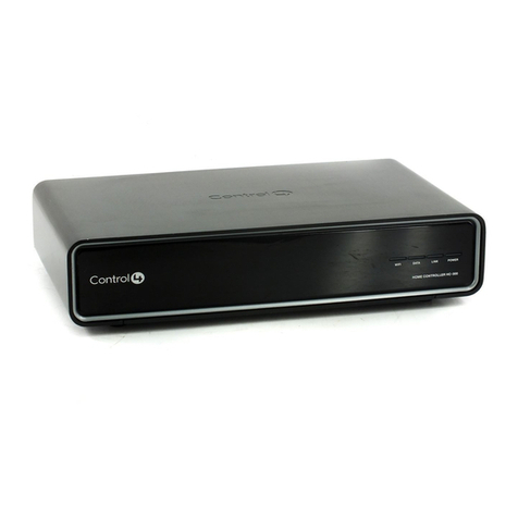
Home Controller HC-300
Installation Guide
Supported Model
C4-HC300C-E-B Home Controller HC-300
Important Safety Instructions
1. Read these instructions.
2. Keep these instructions.
3. Heed all warnings.
4. Follow all instructions.
5. Do not use this apparatus near water.
6. Clean only with dry cloth.
7. Install in accordance with the manufacturer’s instructions.
8. Do not install near any heat sources such as radiators, heat registers,
stoves, or other apparatus (including amplifiers) that produce heat.
9. Do not defeat the safety purpose of the polarized or grounding-type plug. A
polarized plug has two blades with one wider than the other. A grounding
type plug has two blades and a third grounding prong. The wide blade or the
third prong are provided for your safety. If the provided plug does not fit into
your outlet, consult an electrician for replacement of the obsolete outlet.
10.Protect the power cord from being walked on or pinched particularly at
plugs, convenience receptacles, and the point where they exit from the
apparatus.
11.Only use attachments/accessories specified by the manufacturer.
12.Unplug this apparatus during lighting storms or when unused for long peri-
ods of time.
13.Refer all servicing to qualified service personnel. Servicing is required when
the apparatus has been damaged in any way, such as power-supply cord or
plug is damaged, liquid has been spilled or objects have fallen into the
apparatus, the apparatus has been exposed to rain or moisture, does not
operate normally, or has been dropped.
14.This apparatus has no AC mains power switch. The power cable is the AC
mains disconnect device.
WARNING! To reduce the risk of electrical shock, do not expose this
apparatus to rain or moisture.
WARNING! This CLASS I apparatus must be connected to an AC
mains socket outlet that has a protective earthing connection (i.e., third-
prong ground conductor). DO NOT DEFEAT THE PROTECTIVE
EARTHING CONNECTION!
Introduction to Home Controller HC-300
The Control4® Home Controller HC-300 provides options for controlling lights,
home theaters, distributed audio systems, and other devices controlled using
various protocols, such as Infra Red (IR), Serial, Contact, and Relay. It
provides extensive media management services for audio sources, such as
CDs and DVDs stored in connected devices. It allows you to use an external
storage device with USB support for media storage, and it has multi-zone audio
capabilities that can send music to rooms throughout the home.
Once the controller and other system components are installed and configured
(using Control4 Composer software or another Control4 setup program), your
users can control the system using one of the two (2) user interfaces included
with this controller: On-screen Navigator or System Remote Control or any
other Control4 user interface device (available separately).
Control4 Supported Devices
Control4® devices that can be controlled by this controller include:
For a more information see Support > Product Information in the Dealer portal
at http://www.control4.com.
Requirements and Specifications
Prior to installing this product, ensure that: Ethernet network wiring is in place.
The Home Controller HC-300 specifications include:
What’s in the Box
The following are included in your Home Controller box:
• Home Controller HC-300
• Pluggable terminal block connector (1)
• System Remote Control with LCD Navigator display and 4 AAA batteries
• IEC 320 power cord
• IR emitters (6)
• Home Controller HC-300 Installation Guide (this document). Note: You can
find this and other documents online also at the Dealer portal: http://
www.control4.com/dealer/dealer-login/ under Support > Product Informa-
tion.
Accessories Available for Purchase
• USB WiFi Adapter for HC-300 (C4-NWA-11G-USB)
Additional Resources
The following resources are available to provide you with additional support.
• HC-300 Wall Template, part # 851-00001, available at:
http://www.control4.com/dealer/support/pid.htm
• Your Control4 Reseller
• Control4 Web Site: http://www.control4.com
• Composer online help
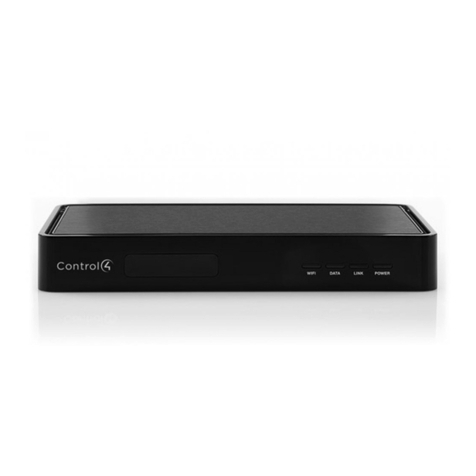
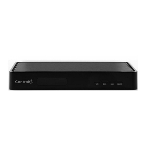
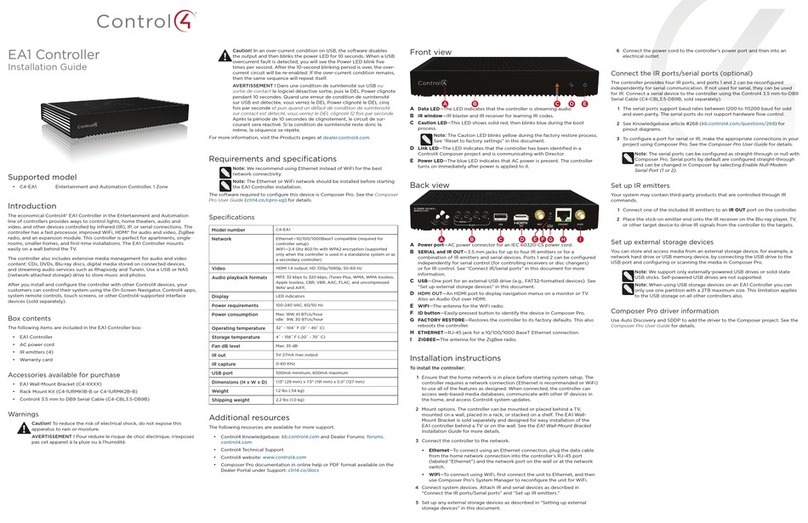
Front View
1. WiFi LED—This LED blinks first red, then orange, and finally blue during
the boot process. Once the operating system is running, the WiFi driver
changes the LED color depending on the signal strength of its connection to
its associated access point. Colors and signal strength are as follows:
orange = Fair to Good, blue = Excellent, and no light = No connection.
2. Data LED—This blue LED indicates streaming audio is received.
3. Link LED—Blue LED light indicates Home Controller has been identified in
a Control4 Composer project.
4. Power LED—Blue LED light indicates AC power is present. It turns on
immediately after the power is applied to the device.
5. IR Window / IR Blaster—For capturing third-party IR codes from hand-held
devices (such as remote controls) or blasting IR codes.
Back View
1. Power plug port—AC power receptacle for an IEC 320 power cord.
2. Video Out—Composite RCA, S-VIDEO mini-DIN, and Component RCA
jacks.
3. Audio Out (2 Left-Right pairs)—RCA jacks for stereo channel line output
(line level) for amplifiers or audio switches.
4. Audio In (1 Left-Right pair)—RCA jacks for stereo channel input (line
level) for one stereo analog source.
5. Video Sense In-Out (2 pairs)—Composite In-Out RCA jack pairs for moni-
toring the On/Off status of up to two video sources.
6. Ethernet—RJ-45 jack for a 10/100 BaseT Ethernet connection.
7. Factory Restore Button—Restores the controller to the factory defaults.
8. USB (1 port)—For external storage device with USB support (such as
FAT32 formatted devices) and WiFi adapter (C4-NWA-11G-USB).
9. Contact (1 set)—Pluggable terminal block connector for one dry contact
closure, logic input connection, door contact sensor, or motion sensor.
10.Relay (1 set)—Pluggable terminal block connector for one normally closed
or normally opened switchable connection.
11.Serial (2 sets, DB9)—Two serial devices, such as a receiver or disk
changer.
12.IR Out (6)—3.5 mm jacks for up to six IR output transmitters.
13. Identification button—Easily-pressed button used when identifying this
device in Composer.
Install the System
To install this controller:
1. Ensure that your home network is in place before starting your system
setup: The Home Controller HC-300 requires a network connection (wired
or WiFi) in order to use all features as designed. When connected, the
Home Controller can access Web-based media databases and Control4
system updates.
2. If mounting directly to a wall:
a. Obtain the HC-300 Wall Template, part # 851-00001, available at:
http://www.control4.com/dealer/support/pid.htm
b. Attach the template to the wall with tape, then level it.
c. Screw or nail 4 screws or nails into the wall where indicated.
d. Remove template from wall.
e. Pull to remove rubber strips from the feet of the HC-300 to expose
the prepared wholes (no need to remove the existing screws).
f. Hang the HC-300 on the wall.
3. Connect the HC-300 controller to the network: To connect using an
Ethernet connection, plug the data cable from the home network connection
into the Home Controller RJ-45 port (labeled “Ethernet”) and the network
port on the wall or at the network switch. To connect using the optional USB
WiFi adapter (C4-NWA-11G-USB), refer to the installation instructions
shipped with the adapter.
4. Power up the controller: Plug the HC-300 power cord (provided) into the
Home Controller power plug port and an electrical outlet.
NOTE: The HC-300 may take several minutes to boot up and become
operational. Please allow sufficient time for boot-up.
5. Connect system devices as described in the “Connect Devices” section
that follows.
6. Set up external storage devices as described in “Set up External Storage
Device” on page 2.
Connect Devices
NOTE: You can use Composer software to step through the connection
process before or after the physical connections are complete.
Connect all applicable devices to the Home Controller HC-300 using one of the
connection options described in the following table.
Table 1. Connection Options
Touch Screen (All types and sizes, such
as portable, tabletop, and wall-mounted,
or 10.5” and mini)
LCD Keypads
Wireless 2, 3, & 6 Button Keypads
Wireless Thermostat
Speaker Point™
Audio Matrix Switch
Supported Third-Party devices
Multi Channel Amplifier
4-Zone Amplifiers
Multi Tuners
Wireless Dimmers
Wireless Switches
Wireless Outlet Dimmers
Wireless Outlet Switches
Model Number • C4-HC300C-E-B
Network Support • Ethernet---required
• WiFi--optional, requires a WiFi adapter (sold
separately)
Media Recognition • Online CD/DVD recognition and media infor-
mation service
Audio Playback Formats • MP3: 32kbps to 320kbps, CBR and VBR
Display • LED indicators
Power Requirements • 100-240 VAC, 60/50 Hz, 0.26 A MAX
Dimensions • H x W x D: 2.80” (71 mm) x 11.98” (304 mm) x
7.24” (184 mm) (with feet and connectors)
Weight • 4.7 pounds
5
1 2 3 4
1 2 3 4 5 6
7 8 9 10 11 12 13
Power plug port—For use with the IEC 320 power connector
(provided).
Video Out Options—Composite, Component, or S-Video
port for displaying navigation menus on a monitor or TV.
The Component jack is only for displaying high-definition
video. To display standard definition video, use the Compos-
ite or S-Video ports. When available, use S-Video instead of
Composite for a higher quality display.
Audio Out (2 Left-Right pairs)—RCA jacks for stereo chan-
nel line output (line level) for amplifiers or audio switches.
Audio In (1 Left-Right pair)—RCA jacks for stereo channel
input (line level) for one stereo analog source.
The following section teaches more about other connection options.
Use Video Sense Loops
Video sensing can enhance the ability to sense the power state of a device,
such as whether the device is “on” or “off.” To add video signal sensing
capabilities for a video device (such as a VCR, DVD player, etc.), connect one
of the device’s composite Video Out ports to a HC-300 Video Sense In port.
Use the companion Video Sense Out port for the device’s video out as needed.
For Video Sense only (no loop-through), connect a device’s Composite Video
Out port to one of the two Video Sense In ports.
Use Pluggable Terminal Block Connectors
For the Contact and Relay ports, the HC-300 makes use of a pluggable
terminal block connector—a removable plastic part that locks in individual
wires, which is included. To connect a device to the Pluggable Terminal Block:
1. Insert one of the wires required for your device into the appropriate opening
in the Pluggable Terminal Block you reserved for that device (refer to
Figure 1 on page 2). For example, if you were adding a motion sensor, you
would connect its wires to the following Contact openings: power input to
+12V output signal to SIG, and ground connector to GND. See the sections
that follow for instruction on connecting the various protocols.
2. Lower the openings latch until it locks the wire in place.
3. Repeat Steps 1-2 for all wires required for your device.
NOTE: When you connect dry contact closure devices, such as door switches,
connect the switch between +12V (Power) and SIG (Signal).
Connect to the Contact Port
The HC-300 provides one contact port as a subset of the pluggable terminal
block provided. See the following figures to determine how to connect the
device to a contact port.
Figure 1: Contact Port for Voltage Source (i.e. Motion Sensor)
Figure 2: Contact for Dry Contact (i.e. Door Contact Sensor)
Figure 3: Contact for Self-Powered Voltage Source Device
Connect to the Relay Port
The HC-300 provides one relay port as a subset of the pluggable terminal block
provided. For most applications, attach one wire to the common terminal and
the other to the normally open terminal. The relay switches closes when the
relay is activated. The HC-300 can support applications that require a normally
closed contact.
Figure 4: Relay Port: Normally Open
Figure 5: Relay Port: Normally Closed
Connect the Serial Ports
The HC-300 provides two DB9-style serial ports. Connect a device to the HC-
300, like a receiver or disk changer, by aligning the pins and tightening the
screws. See the table below for serial communication values.
Set Up IR Emitters or IR Blaster
Your system may contain third-party products that are controlled with IR
commands (usually through remote controls). To provide a way for the Home
Controller to control a device that only recognizes IR commands, complete one
of the following setups: IR Emitters or IR Blaster.
IR Emitters
1. Plug the 3.5 mm connector end of one of the six IR stick-on emitters pro-
vided into an IR Out port on the HC-300.
2. Place the stick-on emitter end over the IR receiver on the media player, TV,
or other target device to reve IR signals from the HC-300 to the target.
IR Blaster
In addition to IR emitters, the HC-300 is also equipped with an IR blaster, which
is located under the front LEDs. To use the blaster instead of an IR emitter:
1. In Composer, connect IR Out #6 of the Home Controller to the IR In of the
device you want to control.
2. Do not physically connect anything to IR Out Port #6.
3. Test and verify that the HC-300 is positioned in such a way that the blaster
can reach the device you want to control.
Set up External Storage Device
You can store and access media from an external storage device, such as a
network hard drive or USB memory device by plugging the USB drive into one
of the USB ports and configure or scan the media from Composer.
Troubleshooting
Factory Restore Button
1. To restore the HC-300 for system recovery to the factory default image, on
the back of the device insert the end of a paper clip into the small hole (to
the right of the Audio In jacks).
2. Power cycle the device while pressing and holding the Factory Restore but-
ton. After about 5 to 7 seconds, the Status LED will start blinking orange to
indicate the start of the recovery process. After the Status LED starts blink-
ing orange, you can release the button.
Identification Button
1. To reset to the network defaults, on the front of the device power cycle the
HC-300 and hold the Identification button until the Data, Link, and Power
LEDs are solid blue; immediately release the button.
2. If during the boot sequence, the Status LED stays Orange, press and hold
the Identification button until the LED blinks Blue, and then release it.
Regulatory Compliance
FCC/Industry Canada
FCC ID: R33C4HC3002/Canadian ID IC:7848A-C4HC300E
This device complies with Part 15 of the FCC Rules. Operation is subject to the
following two conditions: (1) This device may not cause harmful interference,
and (2) this device must accept any interference received, including
interference that may cause undesired operation.
This equipment has been tested and found to comply with the limits for a Class
B digital device, pursuant to Part 15 of the FCC Rules. These limits are
designed to provide reasonable protection against harmful interference in a
residential installation. This equipment generates, uses, and can radiate radio
frequency energy and, if not installed and used in accordance with the
instructions, may cause harmful interference to radio communications.
However, there is no guarantee that interference will not occur in a particular
installation. If this equipment does cause harmful interference to radio or
television reception, which can be determined by turning the equipment off and
on, the user is encouraged to try to correct the interference by one of the
following measures:
• Reorient or relocate the receiving antenna.
• Increase the separation between the equipment and receiver.
• Connect the equipment into an outlet on a circuit different from that to which
the receiver is connected.
• Consult the dealer or an experienced radio/TV technician for help.
Australian / New Zealand
• AS/NZS 4268:2003 + A1:2005 & A2:2006
Recycling
For recycling information, please go to www.control4.com/recycling.
Limited Warranty
For complete warranty information, see http://www.control4.com/dealer/.
About This Document
© 2010 Control4. All Rights Reserved. Control4, the Control4 logo and
Everyday Easy are registered trademarks or trademarks of Control4
Corporation in the United States and/or other countries. All other names or
brands may be claimed as property by their respective owners. 6/22/2010.
Part Number: 200-00185 Rev D, 7/9/2010
Video Sense In-Out (2 pairs)—Composite In-Out port pairs
for monitoring up to two video In sources, such as DVD play-
ers or VCRs, that allow the system to determine the On/Off
status of devices. Each Out port allows the signal to loop
through the Controller and continue to its intended video con-
nection. See “Use Video Sense Loops” for information.
Ethernet—RJ-45 for a 10/100 BaseT Ethernet connection.
USB (1 port)—For external storage device with USB support (such
as FAT32 formatted devices). See “Set up External Storage Device”
for information or to connect the optional WiFi adapter C4-NWA-11G-USB.
Contact (1 set)—Pluggable terminal block connector for one dry
contact closure, logic input connection, door contact sensor, or
motion sensor. Provides power for small devices (12V), signal
input (SIG), and return path (GND).
Relay (1 set)—Pluggable terminal block connector for one nor-
mally closed or normally opened switchable connection, such as a
blind, a fireplace, or a projector screen. The set contains a con-
nection for Normally Opened (NO), Normally Closed (NC), and
Common (COM).
Serial (2 sets)—DB9 connector for a serial device, such as a
receiver or disk changer. See “Connect the Serial Ports” for
more information.
IR Out (6)—3.5 mm jacks for up to six IR output transmitters.
See “Set Up IR Emitters or IR Blaster” for more information.
Hardware
Flow Control Odd Parity Even Parity No Parity
Serial Port1 X X X
SerialPort2XXXX

Other Contro l4 Controllers manuals

Contro l4 C4-4SF120 Series User manual

Contro l4

Contro l4 C4-4SF120 Series User manual

Contro l4 CORE-3 User manual

Contro l4

Contro l4 CORE-3 User manual

Contro l4 CA-10 User manual

Contro l4

Contro l4 CA-10 User manual

Contro l4 HC-250 User manual

Contro l4

Contro l4 HC-250 User manual

Contro l4 CA-1 User manual

Contro l4

Contro l4 CA-1 User manual

Contro l4 C4-CORE-LITE User manual

Contro l4

Contro l4 C4-CORE-LITE User manual

Contro l4 AVM-MC1-B User manual

Contro l4

Contro l4 AVM-MC1-B User manual

Contro l4 C4-EA3-V2 User manual

Contro l4

Contro l4 C4-EA3-V2 User manual

Contro l4 CA-1 User manual

Contro l4

Contro l4 CA-1 User manual

Contro l4 HC-800 User manual

Contro l4

Contro l4 HC-800 User manual

Contro l4 C4-CORE1 User manual

Contro l4

Contro l4 C4-CORE1 User manual

Contro l4 HC-250 User manual

Contro l4

Contro l4 HC-250 User manual

Contro l4 HC-300 User manual

Contro l4

Contro l4 HC-300 User manual

Contro l4 HC-250 User manual

Contro l4

Contro l4 HC-250 User manual

Contro l4 EA-3 User manual

Contro l4

Contro l4 EA-3 User manual

Contro l4 HC-300 User manual

Contro l4

Contro l4 HC-300 User manual

Contro l4 AVM-HTC1-B User manual

Contro l4

Contro l4 AVM-HTC1-B User manual

Contro l4 CORE-5 User manual

Contro l4

Contro l4 CORE-5 User manual

Contro l4 C4-HC200-E-B User manual

Contro l4

Contro l4 C4-HC200-E-B User manual

Contro l4 C4-4SF120 User manual

Contro l4

Contro l4 C4-4SF120 User manual

Contro l4 C4-HC500-E-B User manual

Contro l4

Contro l4 C4-HC500-E-B User manual

Contro l4 EA-5 User manual

Contro l4

Contro l4 EA-5 User manual

Contro l4 C4-4SF120 Series User manual

Contro l4

Contro l4 C4-4SF120 Series User manual

Contro l4 HC-1000 V2 User manual

Contro l4

Contro l4 HC-1000 V2 User manual

Popular Controllers manuals by other brands

Telenot B&B F6 operating instructions

Telenot

Telenot B&B F6 operating instructions

Field Controls 46298500 manual

Field Controls

Field Controls 46298500 manual

dixell T66 Installing and operating instructions

dixell

dixell T66 Installing and operating instructions

Magnetek SBN Series instruction manual

Magnetek

Magnetek SBN Series instruction manual

ABB PLUTO Safety-PLC operating instructions

ABB

ABB PLUTO Safety-PLC operating instructions

Rosemount 54E instruction manual

Rosemount

Rosemount 54E instruction manual

Dungs DSLC px Vx Operation and assembly instructions

Dungs

Dungs DSLC px Vx Operation and assembly instructions

Holland Green Science Aeolus 10209001 user manual

Holland Green Science

Holland Green Science Aeolus 10209001 user manual

Furuno GC-001 user guide

Furuno

Furuno GC-001 user guide

SKYDANCE RGBW user guide

SKYDANCE

SKYDANCE RGBW user guide

Audio Linear M431PSv12 user guide

Audio Linear

Audio Linear M431PSv12 user guide

Atlas Copco EBL Drive Configuration manual

Atlas Copco

Atlas Copco EBL Drive Configuration manual

Danfoss EKA 183A installation guide

Danfoss

Danfoss EKA 183A installation guide

DreamGEAR Radium user guide

DreamGEAR

DreamGEAR Radium user guide

Danfoss VLTAutomationDrive FC 360 quick guide

Danfoss

Danfoss VLTAutomationDrive FC 360 quick guide

National Instruments PXI-8231 installation guide

National Instruments

National Instruments PXI-8231 installation guide

Omron R88A-MCW151 Series datasheet

Omron

Omron R88A-MCW151 Series datasheet

Rain Bird MDC2 instructions

Rain Bird

Rain Bird MDC2 instructions

manuals.online logo
manuals.online logoBrands
  • About & Mission
  • Contact us
  • Privacy Policy
  • Terms and Conditions

Copyright 2025 Manuals.Online. All Rights Reserved.