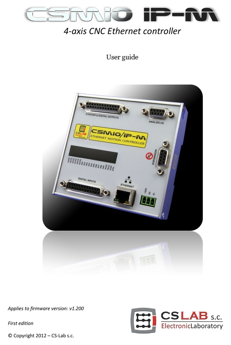
CS-Lab CSMIO/IP-M User manual

Applies to firmware version: v1.200
First edition Rev 1.2
© Copyright 2012 – CS-Lab s.c.

Index
1. General...........................................................................................................................................4
1.1 Signs used in this guide ............................................................................................................... 4
1.2 Contents ...................................................................................................................................... 5
1.3 Standards compliance.................................................................................................................. 6
1.4 Specification................................................................................................................................ 6
2. Safety ............................................................................................................................................7
2.1 Example of E-STOP signal connection .......................................................................................... 8
3. Recommendation for mechanical installation ...................................................................................9
4. Connectors, controls and electrical installation of the device ..........................................................10
4.1 Arrangement of the connectors on the device ............................................................................ 10
4.2 STEP/DIR controlling signals and digital outputs connector ....................................................... 11
4.3 Digital inputs connector............................................................................................................. 13
4.4 Analog I/O connector ................................................................................................................. 14
4.5 Expansion modules connector.................................................................................................... 14
4.6 Power connector........................................................................................................................ 15
4.7 Communication connector – Ethernet........................................................................................ 15
4.8 Recommended cables................................................................................................................ 16
4.9 Installation examples................................................................................................................. 17
4.9.1 The simplest connection of Inverter using a CSMIO IP-M analog output.......................... 17
4.9.2 Simplified diagram of a XYZ plotter................................................................................... 18
4.9.3 Automatic control of drives power supply (HV) ................................................................. 20
4.10 LED Status lights........................................................................................................................ 21
5. Recommendations and drive selection (motor drives).....................................................................22
6. Precise homing with use of the servo drive and the encoder INDEX signal........................................24
7. LAN connection and configuration .................................................................................................26
7.1 PC direct connection.................................................................................................................. 26
7.2 Local network with router and DHCP .......................................................................................... 28
8. Mach3 program – general information ...........................................................................................29
8.1 Recommended PC configuration ................................................................................................ 31
9. Software installation.....................................................................................................................32
9.1 Mach3 installation ..................................................................................................................... 32
9.2 Microsoft® .Net installation (older operating systems) .............................................................. 33
9.3 Installation of the plug-in for Mach3........................................................................................... 33
9.4 Administrator rights in Windows® Vista and Windows® 7.......................................................... 34
10.Mach3 program configuration........................................................................................................35
10.1 Configuration profile .................................................................................................................. 35
10.2 The first run ............................................................................................................................... 36
CS-Lab s.c. –CNC CSMIO/IP-M controller
Page 2

10.3 Configuration of axes used in the machine................................................................................. 37
10.4 Configuration of the digital input signals.................................................................................... 38
10.5 Configuration of digital output signals........................................................................................ 40
10.6 Configuration of spindle and cooling controlling......................................................................... 42
10.7 Configuration of the resolution, speed and acceleration of the axes............................................ 44
10.8 Configuration of motion directions, homing and software limits ................................................. 45
10.9 Additional configuration functions in the plug-in window ........................................................... 46
10.9.1 Servo drive fault signals.................................................................................................... 46
10.9.2 Override sources tab, feed rate correction speed and spindle revs .................................... 47
10.9.3 Spindle tab, selection of analog output that controls the spindle revs............................... 47
10.9.4 Special functions tab, HVEnable and ServoReset. ............................................................. 48
10.10 Selection of inch/mm units ........................................................................................................ 49
10.11 Parameters in the General Config window. ................................................................................. 49
11.First tests.....................................................................................................................................51
11.1 Checking the input signals ......................................................................................................... 51
11.2 Verification of axes scaling and motion directions...................................................................... 52
11.3 HOMING and software limit switches test................................................................................... 53
11.3.1 First homing...................................................................................................................... 53
11.3.2 SoftLimit switches. ........................................................................................................... 53
11.4 Test of spindle and cooling. ....................................................................................................... 54
12.Sample processing step by step.....................................................................................................55
12.1 Preparation of project and G-Code files...................................................................................... 55
12.2 Preparation of the machine and the Mach program .................................................................... 59
12.3 We begin the work...................................................................................................................... 61
13.A few practical notes about Mach3 program and CSMIO/ IP-M.........................................................63
14.VisualBasic® macros .....................................................................................................................65
14.1 Automatic tool-length measurement.......................................................................................... 65
14.1.1 Configuration .................................................................................................................... 66
14.2 Automatic tool change macro .................................................................................................... 67
15.Addition A – CSMIO/IP-M software updates ...................................................................................68
15.1 How to check your software version........................................................................................... 68
15.2 Updating application (uploader) ................................................................................................. 68
15.3 Plugins file update ..................................................................................................................... 69
15.4 Checking the update .................................................................................................................. 69
CS-Lab s.c. –CNC CSMIO/IP-M controller
Page 3

1. General
CSMIO/IP-M product was designed for customers, who are looking for a compromise between advanced
CSMIO/IP-S controller and a simple LPT based device. The biggest advantage of the CSMIO/IP-M
controller is its reasonable price.
The main designing assumption was working stability – hence the use of Controller to PC connection via
Ethernet (its physical layer is galvanically isolated and protocols we use ensure reliable and fast
transmission even in tough industrial environment). Practically any other interface does not provide the
continuity and reliability of transmission on such a high level as the ETHERNET. That is why it is currently
the worldwide standard for high-speed digital communication.
Another important assumption was simplicity of installation. CSMIO/IP-M does not require any external
electronics for proper operation. Inputs/outputs signals are inside optically isolated, filtered, protected
against short circuit, overheating etc. All signals are adjusted to industry standard 24V. The device is
enclosed in a compact cover, mounted on a DIN-rail, which makes the mechanical and electronic
installation in the control cabinet take less time due to its simplicity.
CSMIO/IP-M works with Mach3 program because of its low price, popularity and enormous ability to adapt
to specific requirements. As a drives control interface the choice was a popular step/direction (step / dir)
standard. It allows controlling both the stepper motor drives and the most modern servo drives. Max.
frequency of stop signal is 125 kHz so it is sufficient value for many uses. What is important the controller
is responsible for pulses generation, the same it ensures that the signal is stable in the frequency domain
and its duty cycle 50%. This enables greater culture of machine work than it is while using LPT based
controller.
1.1 Signs used in this guide
________________________________________________________________________________________________________
Potential danger, possible injury risk.
________________________________________________________________________________________________________
Useful information, tips.
________________________________________________________________________________________________________
Warning, failure to comply with these warnings may lead to inappropriate functioning or damage of
the device.
________________________________________________________________________________________________________
CS-Lab s.c. –CNC CSMIO/IP-M controller
Page 4

1.2 Content
The CSMIO/IP-M package includes DB->Terminal Block adapters for easier wires connection in the control
cabinet. Basic components supplied are:
•1xDB25 -> Terminal Block adapter
•1xDB25 + 1xDB9 -> Terminal Block adapter
•2xDB25 connection tape
•1xDB9 connection tape
In case of lack of any elements listed above, please contact your distributor.
CS-Lab s.c. –CNC CSMIO/IP-M controller
Page 5

1.3 Standards compliance
CSMIO/IP-M controllers were designed and made in accordance with the national and international
standards for industrial control systems based on electronic components:
•Detailed requirements for programmable controllers: working characteristics, shock resistance,
safety etc. EN61131-2 (IEC1131-2), CSA 22.2, UL508
•Compliance with European Guidelines (low voltage, the level of electromagnetic interference
Electromagnetic Compability), the CE marking.
•Electrical and non-combustible properties of insulation materials: UL 746C, UL 94, etc.
•The Product made in lead-free technology, RoHS compliant.
1.4 Specification
Parameter
Value
Digital inputs
12
Digital outputs
4
Relay outputs
2
Analog inputs
2
Analog outputs
2
Supply voltage
24VDC +/-10%
Power consumption
5W
Maximum I/O Voltage
30VDC
Maximum output line load
250mA
Analog Input Voltage
0-10VDC
Analog Output - Maximum Load
5mA
Axis Drives control type
(STEP/DIR)
Maximum frequency of the STEP signal
125kHz
STEP Signal Duty Cycle
50%
PC communications
Ethernet 10/100Mb
Ambient temperature range
0oC to +60oC
Relative Humidity (Non-Condensing)
10% to 95%
(without condensation)
The STEP outputs signal frequency is in no way limited by the „Kernel speed” settings in Mach3 program.
While using the CSMIO/IP-M controller this Mach3’s configuration parameter is unused and can be set at
any value.
CS-Lab s.c. –CNC CSMIO/IP-M controller
Page 6

2. Safety
The CSMIO / IP-M device is powered by 24V safe voltage. I / O control lines are optically isolated, also the
PC connection is galvanically isolated. The device does not constitute a direct threat to the health and life
of the user.
Designing a complete control system (control cabinet), you should draw attention to several issues, so
that the entire system does not pose any hazard during use.
Always use the NC contacts for limit switches and safety switch. Thanks to it - a wiring mistake or i.e.
plug-ins disconnection will stop the machine.
Pay special attention to the emergency stop circuit. The control system must be designed in such a way
that when you press the emergency stop mushroom, controlled machine stops immediately in all axes.
You should also take into account the possibility of failure of particular system components such as the
main controller, or axis drives.
For that purpose you can use (not required) a standard safety relay (i.e. from PILZ Company). The safety
switch mushroom, FAULT signals of the drives and inverter and eventually other alarm signals – you
should connect to the input circuits. The output or outputs should be connected to the CSMIO/IP-M
controller, and defined as the emergency stop. Outputs of the security module should be also connected to
the axis drives, inverters, etc. This way we get double protection – if, by inappropriate configuration or
CSMIO/IP-M controller failure - the emergency would not work, the information goes to the axis drives,
which can properly respond to it. It works both sides: if the drives would not react, you always have the
controller.
CSMIO-IP/M Controller in the active state on the input line - defined as E-Stop, blocks the STEP signals
within 0.0001 s. It happens autonomously, without Mach3 program and thus the machine stops very fast.
The same happens with reaction to signals from limit switches.
CS-Lab s.c. –CNC CSMIO/IP-M controller
Page 7

2.1 Example of E-STOP signal connection
The simple example above shows the E-Stop signal connection to the CSMIO/IP-M controller and to the
axis drives, using a Pilz company safety relay (PNOZ X7 24V). S1 is a reset button (safety relay switching
on), S2 is an emergency stop.
This module has one input with all the alarm sources connected to this input (A1). In addition to the
mentioned emergency stop (S2) there are NC contacts - NC1 and NC2, which may be, i.e. opening sensors
for the cover and the control cabinet. Moreover, there are drives’ FAULT signals connected in series. Two
outputs of the safety relay were used as an E-Stop signal for the CSMIO/IP-M controller and axis drives.
This combination assures the machine stops in case of failure on any axis (FAULT signals of the drives),
by pressing emergency stop mushroom and opening the cabinet or cover. Separation of the safety relay
output channels gives double protection for the system and significantly increases the reliability of the
entire system.
PILZ
PNOZ X7 24 V
CS-Lab s.c. –CNC CSMIO/IP-M controller
Page 8

3. Recommendation for mechanical installation
CSMIO/IP-M controller and DB->Terminal block - connection modules were designed to be installed on
standard DIN-rail. It is the quickest and best way of installation.
The Controller uses a small amount of energy and creates a negligible amount of heat.The aluminum
housing provides adequate cooling for the electronics inside, even if the ambient temperature reaches
40OC (104OF).
As for the controller, there are no special precautions for ventilation and the minimum clearance
distances. However, usually, next to the controller in the control cabinet, there are also inverters, power
supplies, motor drives - these components emit a lot of heat, so you should always remember about their
proper location and proper ventilation of the cabinet.
Here is an example of components arrangement in the control cabinet.
Caution is advised during the mechanical and electrical installation. Poorly tightened cable may cause
many problems; it is also very difficult to find such a defect while launching/using the system.
CS-Lab s.c. –CNC CSMIO/IP-M controller
Page 9

4. Connectors, controls and electrical installation of the device
4.1 Arrangement of the connectors on the device
Detailed description of signals on individual connectors is in the following section.
DB->Terminal block modules have the same pin numbers as DB connectors in CSMIO/IP-M device.
For example: the 15 pins of DB25 connector match with the 15 pins on the terminal block.
Signals that control the drives (STEP/DIR)
and digital outputs (relays etc.)
Analog inputs and outputs (0-10V)
Expansion module connector
Power connector
Digital inputs
Communication
connector (ETHERNET)
CS-Lab s.c. –CNC CSMIO/IP-M controller
Page 10

4.2 STEP/DIR controlling signals and digital outputs connector
While connecting the STEP/DIR signals to the motor drive (both servo and stepper drives) pay attention to
which STEP edge is active. The active edge in the CSMIO/IP-M is the leading edge – Change of the STEP+
signal from the logic “0” state (0V) to logic “1” (5V).
PIN number Description
1
DIR[0]+
2
STEP[0]+
3
DIR[1]+
4
STEP[1]+
5
DIR[2]+
6
STEP[2]+
7
DIR[3]+
8
STEP[3]+
9
24V power supply for 0..3 outputs
10
Output 0
11
Output 2
12
Output 4 (NO1 relays)
13
Output 5 (NO2 relays)
14
DIR[0]-
15
STEP[0]-
16
DIR[1]-
17
STEP[1]-
18
DIR[2]-
19
STEP[2]-
20
DIR[3]-
21
STEP[3]-
22
0V power supply for 0..3 outputs
23
Output 1
24
Output 3
25
Common PIN for relay outputs 4
and 5
The differential outputs on this
connector, have low permissible load
(50mA) and serves only to control the
LEDs in the optically isolated inputs
of motor controller.
Pay special attention during
connection because STEP/DIR signals
are not protected against short
circuit and voltage higher than 5V!
Digital outputs have 250mA
permissible load. Pay attention - if
you connect large inductance you
may need to use an additional surge
led, preferably as close to the coil as
possible.
CS-Lab s.c. –CNC CSMIO/IP-M controller
Page 11

During launching the machine it is worth checking to see if the step signal is polarized properly. The
easiest way is to mark a reference on the axis shaft of motor and on the cover. Now prepare and run a test
g-code, it should consist of short rides of the test axis. For X axis it will look like below:
G0 X0
G1 X5 F4000
G1 X0
G1 X5
…
G1 X0
M30
Run this test for several minutes then you should check if the marks line up on the motor shaft and the
cover. If the marks do not match it may mean improper polarization of the STEP signal. You should
change the polarization in the Mach3 program (menu Config/Ports & Pins/Motor Outputs - select/deselect
„STEP Low Active”) and run the test again. Of course, you can also use appropriate measurement tools
instead.
CS-Lab s.c. –CNC CSMIO/IP-M controller
Page 12

4.3 Digital inputs connector
PIN number
Description
1
0 (+) Input
2
1 (+) Input
3
2 (+) Input
4
3 (+) Input
5
4 (+) Input
6
5 (+) Input
7
6 (+) Input
8
7 (+) Input
9
8 (+) Input
10
9 (+) Input
11
10 (+) Input
12
11 (+) Input
13
GND
14
0 (-) Input
15
1 (-) Input
16
2 (-) Input
17
3 (-) Input
18
4 (-) Input
19
5 (-) Input
20
6 (-) Input
21
7 (-) Input
22
8 (-) Input
23
9 (-) Input
24
10 (-) Input
25
11 (-) Input
Pay special attention to not exceed
the permissible voltage (30VDC) on
the inputs lines. It may cause the
device damage.
GND is not used in this case and it
should not be connected.
CS-Lab s.c. –CNC CSMIO/IP-M controller
Page 13

4.4 Analog I/O connector
4.5 Expansion modules connector
PIN number
Description
1
Analog output 0
2
GND
3
Analog input 1
4
-
5
10V (max. 50mA)
6
Analog output 1
7
Analog input 0
8
GND
9
-
PIN number
Description
1
CAN H
2
RS232 RxD
3
RS232 TxD
4
-
5
GND
6
CAN L
7
RS485 B-
8
RS485 A+
9
-
Pay special attention to not exceed the permissible voltage (10VDC) on the inputs
lines. It may cause device damage.
10V output has 50mA load and serves only to supply the potentiometers, spindle
speed controllers or other low load devices.
Connector is only to be used to connect to CS-Lab s.c. expansion modules. Do not
plug it into any other devices, PC, etc.
CS-Lab s.c. –CNC CSMIO/IP-M controller
Page 14

4.6 Power connector
4.7 Communication connector – Ethernet
PIN number
Description
1
Power – 24V DC
2
GND
3
Ground
PIN number
Description
1
TX+
2
TX-
3
Rx+
4
-
5
-
6
RX-
7
-
8
-
View of the plug from the
side of connecting wires
Pay special attention to not exceed the permissible voltage (30VDC) on the inputs
lines. It may cause damage of the device.
If your system includes high inductive loads devices such as electromagnets,
solenoids, electromagnetic clutches – it’s recommended to use a separate 24V
power supply for these devices and a separate supply for the CSMIO / IP-M.
It’s recommended to use shielded FTP or STP cat.6 cable.
The network interface has no Auto MDI-MDIX function. So, if connecting the
CSMIO/IP-M directly to a computer you should use a crossover cable. If you
connect it to the network switch or router - use a non-crossover cable.
A crossover cable is supplied with the basic controller.
CS-Lab s.c. –CNC CSMIO/IP-M controller
Page 15

4.8 Recommended cables
Connections type
Recommended cable
Digital In/out
Minimum cross-section 0,25mm2
Analog In/out
Cross-section 0,25mm2 (Shielded or twisted pair
recommended)
Drives controlling (STEP/DIR)
Cross-section 0,25mm2; shielded–twisted. You can possibly
use the FTP computer cable.
Please note that for signals
(STEP + / STEP-) (Dir+ / Dir-
) you should always use twisted
pair cables.
Ethernet Communication wire
Standard Ethernet cable, shielded - FTP, cat. 6. See 4.7
Power
Min. Cross-section 0,5mm2
CAN expansion modules
If modules are mounted on the same DIN rail next to the
controller you can use DB9 plugs clenched on the 9-wire tape
(if further – use shielded twisted pair).
During mechanical and electrical mounting – particular caution is advised. Poorly tightened cable
may cause many trouble; it’s also very difficult to find such a defect while launching/using the
system.
CS-Lab s.c. –CNC CSMIO/IP-M controller
Page 16

4.9 Installation examples
4.9.1 The simplest connection of Inverter using a CSMIO IP-M analog output.
The example above shows the simplest connection of an inverter controlling the spindle in an engraving
plotter.
CSMIO/IP-M used outputs:
CSMIO/IP-M signal
Connector on CSMIO/IP-M
PIN number in CSMIO/IP-
M connector
Inverter function
Analog signal reference
DB9 – Analog I/O
2
Reference potential for analog speed command
0 analog output
DB9 – Analog I/O
1
Speed command signal -0-10VDC
Common PIN for relay
outputs 4 and 5
DB25 – Digital outputs
25
Output 24V for controlling signals
4 relay output
DB25 – Digital outputs
12
Motor Clockwise switching
5 relay output
DB25 – Digital outputs
13
Motor Counter-Clockwise switching
Do not forget to set the configuration parameters of the inverter properly. Incorrect settings may
cause - in the best case - an inverter error, at worst - the spindle motor would be permanently
damaged (such damage is not covered under warranty).
Mach3 program configuration, concerning use of the spindle with speed control was described in a
chapter 10 - "Mach3 Configuration".
Due to the variety of inverters, to facilitate the connection, in the CSMIO / IP-M controller there are
two relay outputs that can control both positive, negative potential and the potential brought by the
inverter.
In the example above the 24 VDC supplied by the inverter was used.
CS-Lab s.c. –CNC CSMIO/IP-M controller
Page 17

4.9.2 Simplified diagram of a XYZ plotter
CS-Lab s.c. –CNC CSMIO/IP-M controller
Page 18

The drawing presented in this section is the simplest implementation of a 3 axis plotter (XYZ).
Two power supplies are used: 24V to supply the CSMIO/IP-M controller and 80V for the stepper motors
drives. Switches used: NC switches for axis homing (HOME) and limit switches (LIMIT). In practice, it is
necessary to build more comprehensives systems; however the example above shows the minimum
connections.
CS-Lab s.c. –CNC CSMIO/IP-M controller
Page 19

4.9.3 Automatic control of drives power supply (HV)
CSMIO/IP-M controller allows for automatic control of drives power supply and some other devices.
Activating this function is described in Chapter 10. The “HV Enable” voltage is switched ON when “Reset”
is requested by Mach3. It stays ON until one of the following conditions exists:
•FAULT signal from any axis drive
•E-Stop signal
•Limit switch activation
•Loss of communication with the Mach3 program
•Error of inside position/speed regulators in CSMIO/IP-M
Here is an example of a digital output used as “HV Enable”. The output number is irrelevant; it is defined in
the configuration window of the Mach3 program.
When you use large contactors for switching off the power, check if the coil doesn’t take more than 250mA
If your contactor coil draws more than 250mA then activate the contactor with a small interposing relay.
With a large contactor it’s good to have a diode and noise-suppression condenser to eliminate the over
voltages generated when switching off the coil.
CSMIO/IP-M controller makes the "HV Enable" voltage control function automatically. Response time for
the events that cause the disconnection is less than 0,0001 second.
Do not forget that digital outputs of the CSMIO/IP-M are fully isolated so they need separate power supply
(9 and 22 PIN on a STEP/DIR & Digital Outputs connector).
CS-Lab s.c. –CNC CSMIO/IP-M controller
Page 20
Table of contents
Other CS-Lab Controllers manuals
Popular Controllers manuals by other brands
GESTRA
GESTRA TA 7 Installation and service instructions

Linear Technology
Linear Technology LT8570 Demo Manual

Hydrocom
Hydrocom Water Controller II user manual
Keysight Technologies
Keysight Technologies M9038A Startup guide
White Rodgers
White Rodgers UNIVERSAL INTEGRATED FURANCE CONTROL... installation instructions
FANOX
FANOX ES400-45 instructions
