COOK CA SWSI User manual

Handling
Lift the fan by the base or lifting eyes. NOTICE! Never lift
by the shaft, motor, or housing.
Storage
If the fan is stored for any length of time prior to
installation, completely fill the bearings with grease or
moisture-inhibiting oil (refer to Lubricants on page 6).
Rotate the wheel several revolutions every three to five
days to keep a coating of grease on all internal bearing
parts.
Store the fan in its original crate and protect it from dust,
debris and the weather.
To maintain good working condition of the fan when it is
stored outdoors, follow the additional instructions below.
• Coat the shaft with grease or a rust preventative
compound.
• Wrap bearings for weather protection.
• Cover the inlet and outlet to prevent the accumulation of
dirt and moisture in the housing.
• Periodically rotate the wheel and operate dampers (if
supplied).
• Periodically inspect the unit to prevent damaging
conditions.
Installation
Motor Installation
Most motors are shipped mounted on the fans with belts
and drives installed. However, extremely heavy motors and
drives are shipped separately. These motors and drives will
require field installation.
Centrifugal Blowers
INSTALLATION, OPERATION, AND MAINTENANCE MANUAL
CA/CF/CP
This publication contains the installation, operation and
maintenance instructions for standard units of the CA, CF,
and CP Centrifugal Blowers.
• CA / CF SWSI • CA DWDI
• CA-4 SWSI • CA-4 DWDI
• CPFD • CPFB
• CAF-DW
• CPA / CPA-A / CPS / CPS-A / CPV
Carefully read this publication and any
supplemental documents prior to any
installation or maintenance procedure.
Loren Cook Company’s catalogs CA/CF & CP provide
additional information describing the equipment, fan
performance, available accessories, and specification data.
For additional safety information, refer to AMCA
publication 410-96, Safety Practices for Users and Installers
of Industrial and Commercial Fans.
All of the publications listed above can be obtained from
Loren Cook Company by phoning (417)869-6474, extension
166; by FAX at (417)832-9431; or by e-mail at
For information on special equipment, contact Loren Cook
Company Customer Service Department at (417)869-6474.
Receiving and Inspection
Carefully inspect the fan and accessories for any damage
and shortage immediately upon receipt of the fan.
• Turn the wheel by hand to ensure it turns freely and
does not bind.
• Inspect dampers (if supplied) for free operation of all
moving parts.
• Record on the delivery receipt any visible sign of
damage.
Rotating Parts & Electrical Shock Hazard:
Disconnect electric power before working on unit.
Follow proper lockout / tagout procedures to ensure
the unit cannot be energized while being installed or
serviced.
A disconnect switch should be placed near the fan in
order that the power can be swiftly cut off, in case of
an emergency and in order that maintenance
personnel are provided complete control of the power
source.
Grounding is required. All field-installed wiring must
be completed by qualified personnel. All field-
installed wiring must comply with National Electric
Code (NFPA 70) and all applicable local codes.
Failure to follow these instructions could result in
death or serious injury.
CA SWSI shown

2
7. place adjusting nut and locking nut on threaded rod
near fan mounting bracket
8. alternately rotate adjusting nut at each mounting
location until the fan weight is uniformly transferred to
the isolators. Remove bracing.
Floor Mounted Spring Isolators
1. Mount fan and motor on isolation base or rails (if
supplied).
2. Elevate fan (or isolation base) to operating height and
insert blocks to hold in position.
3. Position isolators under the fan and vertically align by
inserting leveling bolt through mounting holes in the
fan or the base. The isolator must be installed on a
level surface.
4. Adjust the isolators by turning the leveling nut counter
clockwise several turns at a time alternately on each
isolator until the fan weight is transferred onto the
isolators and the fan raises uniformly off the blocks.
Then remove the blocks.
5. Turn lock nut onto leveling bolt and secure firmly in
place against the top of the mounting flange or frame.
6. Secure isolators to mounting surface.
Floor Mounted Rubber-In-Shear (RIS) Isolators
1. Mount fan and motor on an isolation base or rails (if
supplied).
2. Elevate fan to provide room to insert isolators between
the base and foundation and block in position.
3. Position isolators under fan and secure bolts.
4. Remove blocks and allow fan to rest on floor. Isolators
must be installed on a level surface (leveling should
not be required).
5. Secure isolators to mounting surface.
Rubber-In-Shear Ceiling Isolators
Ceiling Mounted Spring Isolator
Figure 1 - Ceiling Mount Isolators
Figure 2 -Floor Mount Isolators
Rubber-In-Shear Isolator
Spring Isolator
Foundation
This fan requires a strong, level foundation of reinforced
poured concrete. A correctly designed concrete foundation
provides the best means for mounting floor units. The
foundation’s size is determined by fan size and
arrangement, motor size and position, and the specific
location of the installation.
Use the following guidelines to calculate foundation size:
• The overall dimensions of the foundation should
extend at least 6 inches beyond the outline of the fan
and its motor.
• The weight of the foundation should be 2 to 3 times the
weight of the unit and its motor.
Isolation
NOTICE! Although a certain amount of vibration is
inherent in operating centrifugal fans, extreme
vibration is a serious problem that may cause
structural and mechanical failure.
Isolation Base
To prevent vibration and noise from being transferred to
the building isolators are recommended.Arrangement 1, 2,
& 3 (CA or CF) fans require an isolation base to effectively
isolate the fan system which includes the fan, base, motor,
drive, guards, etc. Bases must have sufficient rigidity to
resist belt pull and prevent drive distortion which can lead to
excessive belt and bearing wear; its perimeter should
contain all base angles and rotating parts. Arrangement 9
or 10 fans (CA, CF, and CP) above size 270 require
isolation rails. Please consult factory for isolation of
arrangement 9 fans due to the potential of uneven loading
caused by the motors and drives. Isolators should be
located between the fan system and the support structure.
Ceiling Mounted Spring and Rubber-in-Shear (RIS)
Isolators
1. Mount fan on isolation base or rails
2. Elevate fan to operating height and brace
3. Attach threaded rod to overhead support structure
directly above each mounting hole. Rod should extend
to within a few feet of fan.
4. Attach isolator to end of threaded rod using a nut on
each side of isolator bracket
5. Insert another section of threaded rod through the fan
mounting hole and isolator
6. Attach two nuts to threaded rod isolator
The attachment of roof mounted fans to the roof curb
as well as the attachment of roof curbs to the building
structure must exceed the structural requirements
based on the environmental loading derived from the
applicable building code for the site. The local code
official may require variations from the recognized
code based on local data. The licensed engineer of
record will be responsible for prescribing the correct
attachment based on construction materials, code
requirements and environmental effects specific to
the installation.
Failure to follow these instructions could result in
death or serious injury.

3
sealed with UL recognized fire caulk to both the curb cap
duct adapter and the bottom of the fan. A minimum of two
separate outlines of caulk is recommended at the outer
portion of the curb cap duct adapter.
Wheel-to-Inlet Clearance
The correct wheel-to-inlet clearance is critical to proper
fan performance. This clearance should be verified before
initial start-up since rough handling during shipment could
cause a shift in fan components. Refer to wheel/inlet draw-
ing for correct overlap.
Adjust the overlap by loosening the wheel hub and mov-
ing the wheel along the shaft to obtain the correct value.
A uniform radial gap (space between the edge of the
cone and the edge of the inlet) is obtained by loosening the
inlet cone bolts and repositioning the inlet cone.
CA, CF, & CP
CAF-DW
Size Overlap
60 - 165 3/16”
180 - 245 1/4”
270 - 300 5/16”
330 - 365 3/8”
402 7/16”
445 - 490 1/2”
540 - 730 13/16”
Size Overlap
120 1/8”
135 - 165 5/32”
180 1/4”
195 5/32”
210 1/4”
225 5/32”
245 9/32”
270 - 445 1/4”
490 17/32”
540 - 600 27/32”
660 - 730 25/32”
Duct Installation
Efficient fan performance relies on the proper installation
of inlet and discharge ducts. Be sure your fan conforms to
the following guidelines.
Non-Ducted Inlet Clearance: If your fan has an open
inlet (no duct work), the fan must be placed 1 fan wheel
diameter away from walls and bulkheads.
Free Discharge: Avoid a free discharge into the plenum.
This will result in lost efficiency because it doesn’t allow for
a static regain.
Inlet Duct Turns: For ducted inlets, allow at least 3 fan
wheel diameters between duct turns or elbows and the fan
inlet.
Discharge Duct Turns: Where possible, allow 3 duct
diameters between duct turns or elbows and the fan outlet.
CP with Optional Curb Cap & Inlet Box
UL 762 / NFPA96 and local codes may dictate
additional or modifications to this installation.
The installation diagram below has a solid curb cap duct
adapter placed over the top of the curb. The welded grease
duct with recommended transition is either welded or
MIN 1 DIA
Correct Incorrect
Correct
Incorrect
MIN 3
DIA
Correct Incorrect
MIN 3
DIA

4
1 foot
1/4 inch
rim of the pulley.
2. Slide the motor back until proper tension is reached.
For proper tension a deflection of approximately 1/4”
per foot of center distance should be obtained by firmly
pressing the belt.
3. Lock the motor adjustment nuts in place.
4. Ensure pulleys are properly aligned. Refer to Figure 4.
Pulley Alignment (belt drive)
Pulley alignment is adjusted by
loosening the motor pulley setscrew and
by moving the motor pulley on the motor
shaft.
Figure 4 indicates where to measure
the allowable gap for the drive
alignment tolerance. All contact points
(indicated by WXYZ) are to have a gap
less than the tolerance shown in the
table. When the pulleys are not the
same width, the allowable gap must be adjusted by half of
the difference in width (As shown in A & B of Figure 4).
Figure 5 illustrates using a carpenter’s square to adjust the
position of the motor pulley until the belt is parallel to the
longer leg of the square.
Final Installation Steps
1. Inspect fasteners and setscrews, particularly fan
mounting and bearing fasteners, and tighten according
to the recommended torque shown in the following
table.
2. Inspect for correct voltage with voltmeter.
3. Ensure all accessories are installed.
OFFSET ANGULAR OFFSET/ANGULAR
A
W
X
Y
ZB
CENTER
DISTANCE
(CD)
GAP GAP
Figure 4
Tolerance
Center
Distance Maximum
Gap
Up thru 12” 1/16”
12” up through 48 1/8”
Over 48” 1/4”
Figure 5
Recommended Torque for Setscrews & Hold Down Bolts
Setscrews Hold Down Bolts
Size Key
Hex
Across
Flats
Recommended
Torque
(inch/lbs) Size Wrench Torque
(inch/lbs)
Min. Max.
No.10 3/32” 28 33 3/8”-16 240
1/4” 1/8” 66 80 1/2”-13 600
5/16” 5/32” 126 156 5/8”-11 1200
3/8” 3/16” 228 275 3/4”-10 2100
7/16” 7/32” 348 384 7/8”- 9 2040
1/2” 1/4” 504 600 1”- 8 3000
5/8” 5/16” 1104 1200 1-1/8” - 7 4200
3/4” 3/8” 1440 1800 1-1/4” - 7 6000
Wiring Installation
NOTICE!All wiring should be in accordance with
local ordinances and the National Electrical
Code, NFPA 70. Ensure the power supply
(voltage, frequency, and current carrying
capacity of wires) is in accordance with the
motor nameplate.
(See page 5 for diagram)
Leave enough slack in the wiring to allow for motor
movement when adjusting belt tension. Some fractional
motors have to be removed in order to make the connection
with the terminal box at the end of the motor. To remove
motor, remove bolts securing motor base to power
assembly. Do not remove motor mounting bolts.
Units with Arrangement 10 have a hole provided at the
base of the bearing pedestal to accommodate wiring.
Follow the wiring diagram in the disconnect switch and
the wiring diagram provided with the motor. Correctly label
the circuit on the main power box and always identify a
closed switch to promote safety (i.e., red tape over a closed
switch).
Wheel Rotation
Test the fan to ensure the rotation of the wheel is the
same as indicated by the arrow marked Rotation.
For 115 and 230 Single Phase Motors: Fan wheel
rotation is set correctly at the factory. Changing the rotation
of this type of motor should only be attempted by a qualified
electrician.
For 208, 230, and 460, 3 Phase Motors: These motors
are electrically reversible by switching two of the supply
leads. For this reason, the rotation of the fan cannot be
restricted to one direction at the factory. See Wiring
Diagrams above for specific information on reversing wheel
direction.
NOTICE! Do not allow the fan to run in the wrong
direction. This will overheat the motor and cause
serious damage. For 3-phase motors, if the fan is
running in the wrong direction, check the control
switch. It is possible to interchange two leads at this
location so that the fan is operating in the correct
direction.
Belt and Pulley Installation (belt drive)
Belt tension is determined by the sound the belts make
when the fan is first started. Belts will produce a loud squeal
which dissipates after the fan is operating at full capacity. If
the belt tension is too tight or too loose, lost efficiency and
possible damage can occur.
Do not change the pulley pitch diameter to change
tension. This will result in a different fan speed than desired.
1. Loosen motor adjustment nuts on and move motor in
order that the belts can easily slip into the grooves on
the pulleys. Never pry, roll, or force the belts over the
Airfoil Backward Inclined Forward Curved

5
Fan
Motor
Damper
Motor* Second
Damper
Motor
Transformer** Transformer**
L3
L2
L1
Motor
1
2
3
4
5
6
Together
High Speed
Line
L1
L2
L3
1
2
3
4
5
6Open
Low Speed
Line
L1
L2
L3
Motor
456
1
72
83
9
L1L2L3
456
789
12 3
L1L2L3
Low Voltage
208/230 Volts High Voltage
460 Volts
3 Phase, 9 Lead Motor
Y-Connection
7
1
6789
456
12 3
Low Voltage
208/230 Volts High Voltage
460 Volts
8
2
49
3
5
L1L3
L2
L1L3
L2
3 Phase, 9 Lead Motor
Delta-Connection
T-1
T-4
Ground B
L2
L1
Ground A
Line
Ground A
Ground B
T-1
T-4
Low Speed
High Speed
L1
L2Line
Wiring Diagrams Wiring Diagrams
When ground is required, attach to ground A or B with no. 6 thread forming
screw. To reverse, interchange T-1 and T-4.
Single Speed, Single Phase Motor
To reverse, interchange any 2 line leads.
When ground required, attach to ground A or B with No. 6 thread forming
screw. To reverse, interchange T-1 and T-4 leads.
2 Speed, 2 Winding, Single Phase Motor
2 Speed, 1 Winding, 3 Phase Motor
To reverse, interchange any 2 line leads. Motors require magnetic control.
Single Speed, Single Phase, Dual Voltage
2 Speed, 2 Winding, 3 Phase
When ground required, attach to ground A or B with No. 6 thread forming
screw. To reverse, interchange T-5 and J-10 leads. To reverse: High Speed-interchange leads T11 and T12.
Low Speed-interchange leads T1and T2. Both Speeds-interchange any 2
line leads.
Typical Damper Motor Schematic
For 3 phase, damper motor voltage should be the same between L1and
L2. For single phase application, disregard L3. *Damper motors may be
available in 115, 230 and 460 volt models. The damper motor nameplate
voltageshould be verified prior to connection. **A transformermay bepro-
vided in some installations to correct the damper motor voltage to the
specified voltage.
Ground B
J-10
T-5
Ground A
Link A
Link B
Low Voltage
Line
L2
L1
Ground A
Link A & B L1
L2
Line
Ground B
T-5
J-10
Start Up
Turn the fan on. In variable speed units, set the fan to its
lowest speed and inspect for the following:
• Direction of rotation.
• Excessive vibration.
• Unusual noise.
• Bearing noise.
• Improper belt alignment or tension (listen for
squealing).
• Improper motor amperage or voltage.
NOTICE! If a problem is discovered, immediately
shut the fan off. Lock out all electrical power and check
for the cause of the trouble. See Troubleshooting.
Operation
Pre-Start Checks
1. Lock out all the primary and secondary power
sources.
2. Ensure fasteners and setscrews, particularly those
used for mounting the fan, are tightened.
3. Inspect belt tension and pulley alignment.
4. Inspect motor wiring.
5. Ensure belt touches only the pulleys.
6. Ensure fan and ductwork are clean and free of debris.
7. Inspect wheel-to-inlet clearance. The correct wheel-
to-inlet clearance is critical to proper fan performance.
8. Close and secure all access doors.
9. Restore power to the fan.

6
• Bearings should be inspected as recommended in the
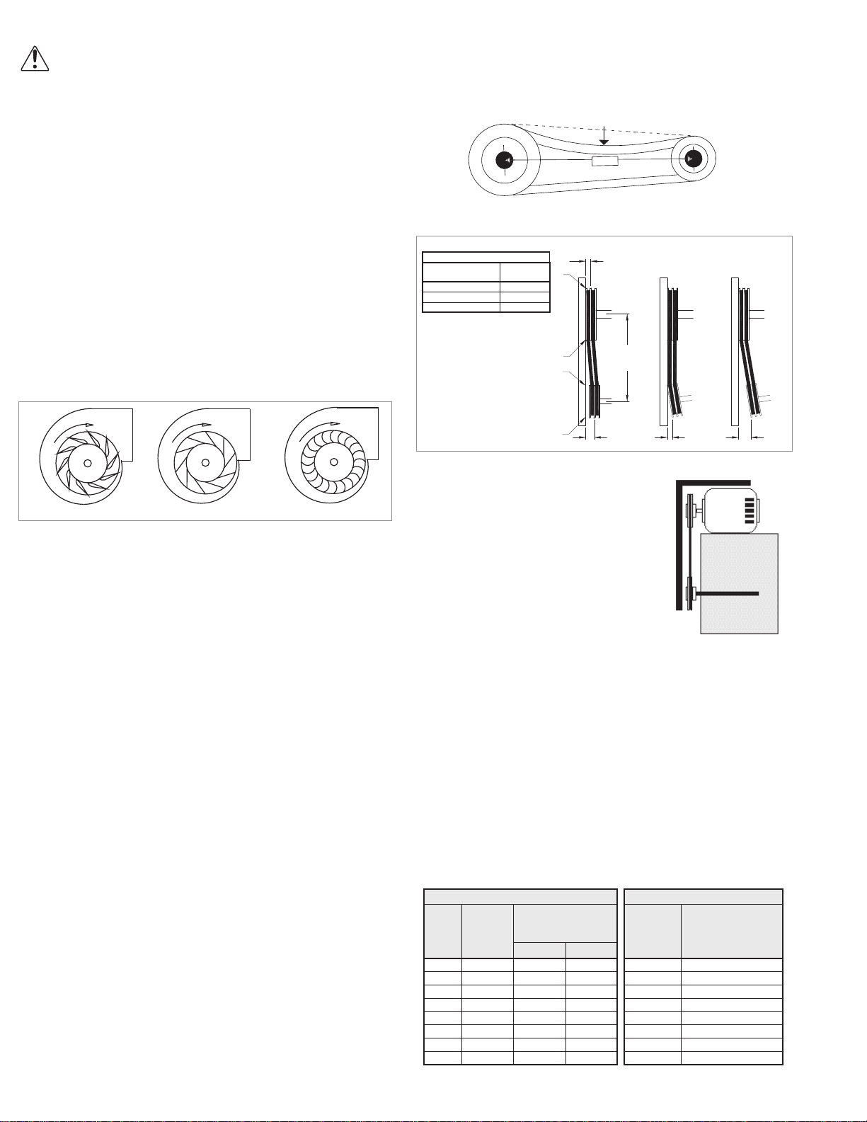
Lubrication Conditions Chart.• Inspect variable inlet
vanes for freedom of operation and excessive wear.
The vane position should agree with the position of the
control arm. As the variable inlet vanes close, the
entering air should spin in the same direction as the
wheel.
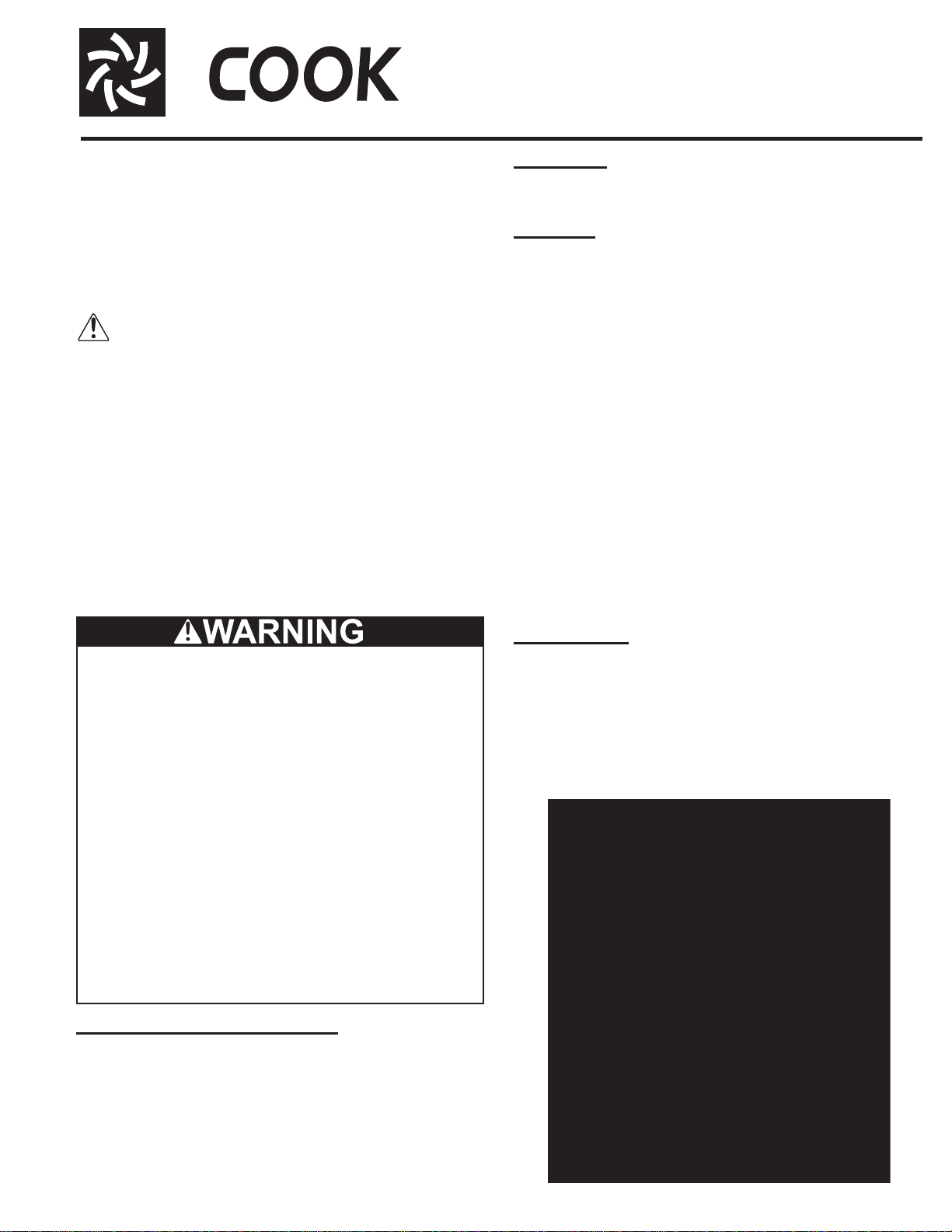
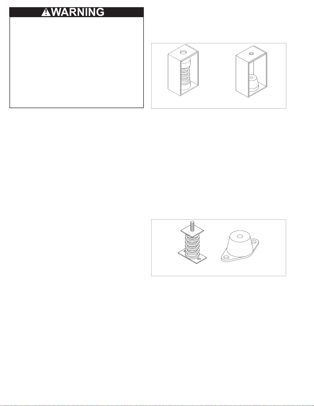
• Inspect springs and rubber isolators for deterioration
and replace as needed.
• Inspect for cleanliness. Clean exterior surfaces only.
Removing dust and grease on motor housing assures
proper motor cooling. Removing dirt from the wheel
and housing prevent imbalance and damage.
Lubrication - Fan Bearings
Greasable fan bearings are lubricated through a grease
fitting on the bearing.
For best results, lubricate the bearing while the fan is in
operation. Pump grease in slowly until a slight bead forms
around the bearing seals. Excessive grease can burst
seals thus reducing bearing life.
Before lubricating, the grease nipple and immediate
vicinity should be thoroughly cleaned without the use of
high pressure equipment. The grease should be supplied
slowly as the bearing rotates until fresh grease slips past
the seal. Excessive pressure should be avoided to prevent
seal damage.
In the event the bearing cannot be seen, use no more
than three injections with a hand-operated grease gun.
NOTICE! Loren Cook Company uses petroleum
lubricant in a lithium base. Other types of grease
should not be used unless the bearings and lines have
been flushed clean. If another type of grease is used, it
should be a lithium-based grease conforming to NLGI
grade 2 consistency. A NLGI grade 2 grease is a light
viscosity, low-torque, rust-inhibiting lubricant that is
water resistant. Its temperature range is from -30F to
Exceptions to the greasing interval chart:
1. Periodic Applications (any break of one week or
more): it is recommended that full lubrication be
performed prior to each break in operation.
2. Higher Temperature: it is recommended to
halve the intervals for every 30F increase in
operating temperature above 120F not to
exceed 230F for standard bearings; High Tem-
perature bearings (optional) can operate up to
400F.
3. Vertical Shaft: it is recommended that the inter-
vals should be halved.
Lubrication Conditions Chart
Fan Class Fan Status Shaft Size Maximum Interval
(operational hrs)
Centrifugal
Blower
Class I
Normal Conditions
(Clean, Dry & Smooth) > 1-1/2” 10,000
< 1-1/2” 2,000
Extreme Conditions
(Dirty/Wet/Rough) > 1-1/2” 2,000
< 1-1/2” 400
Centrifugal
Blower
Class II
Normal Conditions
(Clean, Dry & Smooth) > 2” 7,500
< 2” 1,000
Extreme Conditions
(Dirty/Wet/Rough) > 2” 1,500
< 2” 200
Centrifugal
Blower
Class III
Normal Conditions
(Clean, Dry & Smooth) > 2” 3,000
< 2” 500
Extreme Conditions
(Dirty/Wet/Rough) > 2” 500
< 2” 100
Use of Variable Frequency Drives
Motors
Motors that are to be operated using a Variable
Frequency Drive (VFD) must be VFD compatible. At a
minimum, this must be a Premium Efficiency motor with
Class F insulation. Motors that are not supplied by Loren
Cook Company should have the recommendation of the
motor manufacturer for use with a VFD.
Grounding
The fan frame, motor and VFD must be connected to a
common earth ground to prevent transient voltages from
damaging rotating elements.
Wiring
Line reactors may be required to reduce over-voltage
spikes in the motors. The motor manufacturer should be
consulted for recommended line impedence and usage of
line reactors or filters, if the lead length between the VFD
and the motor exceeds 10 feet (3m).
Fan
It is the responsibility of the installing body to perform
coast-down tests and identify any resonant frequencies
after the equipment is fully installed. These resonant
frequencies are to be removed from the operating range of
the fan by using the “skip frequency” function in the VFD
programming. Failure to remove resonant frequencies
from the operating range will decrease the operating life of
the fan and void the warranty.
Inspection
Inspection of the fan should be conducted at the first 30
minute, 8 hour and 24 hour intervals of satisfactory
operation. During the inspections, stop the fan and inspect
as per the Conditions Chart.
30 Minute Interval
Inspect bolts, setscrews, and motor mounting bolts.
Adjust and tighten as necessary.
8 Hour Interval
Inspect belt alignment and tension. Adjust and tighten as
necessary.
24 Hour Interval
(belt drive) Inspect belt tension, bolts, setscrews, and
motor mounting bolts. Adjust and tighten as necessary.
Maintenance
Establish a schedule for inspecting all parts of the fan.
The frequency of inspection depends on the operating
conditions and location of the fan.
Inspect fans exhausting corrosive or contaminated air
within the first month of operation. Fans exhausting
contaminated air (airborne abrasives) should be inspected
every three months.
Regular inspections are recommended for fans
exhausting non-contaminated air.
It is recommended the following inspection be conducted
twice per year.
• Inspect bolts and setscrews for tightness. Tighten as
necessary. Worn setscrews should be replaced
immediately.
• Inspect belt wear and alignment. Replace worn belts
with new belts and adjust alignment as needed. See
the Belt and Pulley Installation.

7
Maximum RPM
CA SWSI,
CPS-A,
CPA-A, Size
Maximum RPM CA & CAF
DWDI
Size
Maximum RPM
Class
IClass
II Class
III Class
IClass
II Class
III
120 3348 4368 5503 120 3714 4846 6105
135 2976 3883 4892 135 3307 4315 5436
150 2678 3494 4403 150 2575 3357 4230
165 2435 3177 4002 165 2374 3095 3901
180 2114 2757 3474 180 2176 2839 3577
195 1951 2545 3207 195 2009 2621 3302
210 1812 2363 2978 210 1865 2434 3066
225 1691 2206 2779 225 1741 2271 2862
245 1553 2026 2553 245 1631 2128 2681
270 1419 1851 2332 270 1443 1883 2372
300 1277 1666 2099 300 1262 1647 2074
330 1161 1514 1908 330 1147 1496 1885
365 1064 1388 1749 365 1038 1354 1706
402 965 1259 1586 402 941 1228 1547
445 873 1138 1434 445 851 1110 1399
490 793 1034 1303 490 773 1009 1271
540 719 938 1182 540 702 916 1164
600 647 844 1064 600 631 823 1037
660 588 768 967 660 574 749 944
730 532 694 874 730 519 677 853
+200F and capable of intermittent highs of +250F. For
temperatures above 250°F Mobiltemp SHC 32 is
recommended.
Lubrication - Motor Bearings
Motors are provided with prelubricated bearings. Any
lubrication instructions shown on the motor nameplate
supersede instructions below.
Motor bearings without provisions for relubrication will
operate up to 10 years under normal conditions with no
maintenance. In severe applications, high temperatures or
excessive contaminates, it is advisable to have the
maintenance department disassemble and lubricate the
bearings after 3 years of operation to prevent interruption of
service.
For motors with provisions for relubrication, follow
intervals of the following table.
Motors are provided with a polyurea mineral oil NGLI #2
grease. All additions to the motor bearings are to be with a
compatable grease such as Exxon Mobil Polyrex EM and
Chevron SRI.
The above intervals should be reduced to half for vertical
shaft installations.
Motor Services
Should the motor prove defective within a one-year
period, contact your local Loren Cook representative or
your nearest authorized electric motor service
representative.
Changing Shaft Speed (belt drive)
All belt driven fans with motors up to and including 5 HP
(184T max.) are equipped with variable pitch pulleys. To
change the fan speed, perform the following:
1. Loosen setscrew on driver (motor) pulley and remove
key, if equipped.
2. Turn the pulley rim to open or close the groove facing.
If the pulley has multiple grooves, all must be adjusted
to the same width.
3. After adjustment, inspect for proper belt tension.
Speed Reduction: Open the pulley in order that the belt
rides deeper in the groove (smaller pitch diameter).
Speed Increase: Close the pulley in order that the belt
rides higher in the groove (larger pitch diameter). Ensure
that the RPM limits of the fan and the horsepower limits of
the motor are maintained.
R
e
l
u
b
r
i
cat
i
on
I
nterva
l
s
Service
Conditions
NEMA Frame Size
Up to and
including 184T 213T-365T 404T and larger
1800RPM
and less Over1800
RPM 1800RPM
and less Over1800
RPM 1800RPM
and less Over 1800
RPM
Standard 3 yrs. 6 months 2 yrs. 6 months 1 yr. 3 months
Severe 1 yr. 3 months 1 yr. 3 months 6 months 1 months
*Sizes 60 through 100 only applies to CPS
and CPA.
CF SWSI,
CPS, CPA,
Size
Maximum RPM
Class
IClass
II Class
III
60-100* 4230 5519 6953
120 3404 4441 5595
135 3026 3948 4974
150 2723 3553 4476
165 2476 3230 4069
180 2269 2961 3730
195 2095 2733 3443
210 1795 2341 2950
225 1675 2185 2753
245 1539 2007 2529
300 1257 1639 2065
330 1142 1490 1877
365 1023 1334 1681
402 939 1225 1543
445 849 1108 1396
490 771 1006 1268
540 700 913 1150
600 630 822 1035
660 573 747 941
730 518 675 851
CPV
Size Maximum RPM
Standard Reinforced
60-100 2719
--
120 2527
135 2093
150 2035
165 1766
180 1588
195 1429 1571
210 1277 1407
225 1152 1265
245 1015 1260
270 876 1091
300 837 1006
330 716 869
365 624 805
402 539 701
445 463 660
490 360 576
RPM Derating Factor
For elevated airstream temperatures, the max-
imum fan speed limits must be derated by the
factors above.
Temperature
(°F) RPM Factor
Steel Aluminum
70 1.00 1.00
200 0.98 0.93
300 0.96 0.79
400 0.94
-
500 0.91
600 0.87
700 0.81
800 0.75

8
After 24 hours of operation, retighten the setscrews to
the appropriate torque. This assures full locking of the inner
race to the shaft. Make sure the socket key or driver is in
good condition with no rounded corners. The key should be
fully engaged in the setscrew and held squarely to prevent
rounding out of the setscrew socket when applying
maximum torque.
For Arrangement 3: Bearings should be replaced
individually for each side of fan.
1. Loosen and remove belts.
2. If replacing drive side bearing, mark location of pulley
and then remove.
3. Mark bearing location on bearing support and loosen
bearing hold down bolts.
4. Support shaft to remove weight from bearing.
5. Remove anti-corrosion coating from the shaft with a
suitable de-greaser.
6. Remove bearing from the shaft using a bearing puller.
If a bearing puller is not available, tap on the bearing
with a wood block and hammer to remove it.
7. Smooth and clean the shaft and bearing bore
thoroughly.
8. Place the bearing into position making sure it is not on
a worn section of the shaft. Tapping the inner ring face
with a soft driver may be required. Do not hammer on
the housing.
9. The outer ring of the bearing is spherical and swivels
in the housing to compensate for misalignment.
Secure hold-down bolts, but do not fully tighten.
10. Align setscrews on the bearings and tighten one
setscrew on bearing.
11. Rotate the shaft to allow the bearing outer ring to find
its center of free movement.
12. Tighten hold-down bolts to proper torque. Refer to
Torque chart.
13. Turn the shaft by hand. Resistance should be the
same as it was before hold-down bolts were fully
tightened.
14. Tighten bearing setscrews to specified torque.
15. Re-install the pulley if required.
16. Repeat process for opposite bearing.
17. Adjust the belt tension.
18. Test run and retighten all setscrews and bolts; trim
balance as necessary (.0785 in/sec max.).
After 24 hours of operation, retighten the setscrews to
the appropriate torque. This assures full locking of the
inner race to the shaft. Make sure the socket key or
driver is in good condition with no rounded corners. The
key should be fully engaged in the setscrew and held
squarely to prevent rounding out of the setscrew socket
when applying maximum torque.
Pulley and Belt Replacement
1. Remove pulleys from their respective shafts.
2. Clean the motor and fan shafts.
3. Clean bores of pulleys and coat the bores with
heavy oil.
4. Remove grease, rust, or burrs from the pulleys and
shafts.
5. Remove burrs from shaft by sanding.
6. Place fan pulley on fan shaft and motor pulley on its
shaft. Damage to the pulleys can occur when
excessive force is used in placing the pulleys on
their respective shafts.
7. Tighten in place.
8. Install belts on pulleys and align as described in the
Belt and Pulley Installation section.
Bearing Replacement
The fan bearings are pillow block ball bearings.
An emery cloth or file may be needed to remove
imperfections in the shaft left by the setscrews.
For Arrangement 1, 2, 9 and 10:
1. Mark the position on the shaft of both bearing races,
setscrews, and the wheel and pulley. Mark the
location and orientation of the inlet cone. Note the
clearance between the wheel and inlet cone.
2. Remove the fan pulley and inlet cone.
3. Remove the wheel from the shaft. A 2-jaw puller
may be needed.
4. Remove bearing hold-down bolts. Remove shaft
and bearings as one unit.
5. Remove the anti-corrosion coating from the shaft
with a suitable degreaser.
6. Remove the bearing from the shaft using a bearing
puller. If a bearing puller is not available, tap on the
bearing with a wood block and hammer to remove it.
7. Smooth and clean the shaft and bearing bore
thoroughly.
8. Place the bearings into position making sure they
are not on a worn section of the shaft. Tapping the
inner ring face with a soft driver may be required.
NOTICE! Do not hammer the bearing housing.
9. The outer ring of the bearing is spherical and
swivels in the housing to compensate for
misalignment. Secure hold-down bolts, but do not
fully tighten.
10. Align the setscrews on the bearings and tighten
one setscrew on each bearing.
11. Rotate the shaft to allow the bearing outer rings to
find their center of free movement.
12. Install the wheel on the shaft. Install the inlet cone
in its original location. And adjust bearing position
and inlet cone to center the wheel in the inlet cone.
13. Tighten hold-down bolts to proper torque.
14. Turn the shaft by hand. Resistance should be the
same as it was before hold-down bolts were fully
tightened.
15. Tighten bearing setscrews to specified torque.
Refer to the Torque chart.
16. Re-install the pulley and adjust the belt tension.
17. Test run and retighten all setscrews and bolts; trim
balance as necessary (.0785 in/sec max.).

9
Troubleshooting
Problem and Potential Cause
Low Capacity or Pressure:
• Incorrect direction of rotation. Make sure the fan rotates
in same direction as the arrows on the motor or belt
drive assembly.
• Poor fan inlet conditions. There should be a straight
clear duct at the inlet.
• Improper wheel alignment.
Excessive Vibration and Noise:
• Damaged or unbalanced wheel.
• Belts too loose; worn or oily belts.
• Speed too high.
• Incorrect direction of rotation. Make sure the fan rotates
in same direction as the arrows on the motor or belt
drive assembly.
• Bearings need lubrication or replacement.
• Fan surge or incorrect inlet or outlet condition.
Overheated Motor:
• Motor improperly wired.
• Incorrect direction of rotation. Make sure the fan rotates
in same direction as the arrows on the motor or belt
drive assembly.
• Cooling air diverted or blocked.
• Improper inlet clearance.
• Incorrect fan RPMs.
• Incorrect voltage.
Overheated Bearings:
• Improper bearing lubrication
• Excessive belt tension.

10
5
4
3
2
1
612
11
10
9
8
Drive Side View Dischar
g
e Side View Inlet Side View
Drive Side View Dischar
g
e Side View Inlet Side View
5
4
3
2
1
6
7
10
9
8
12
11
CA, CF SWSI Arrangement 9
Parts List
CA,CF SWSI Arrangement 1
CA, CF SWSI Arrangement 3
5
4
3
2
1
6
10
13
98
12
11
14
Drive Side View Dischar
g
e Side View Inlet Side View
7
Part No. Arr 1 Arr 3 ARR 9
1 Motor Slide Base
2 Motor
3 Motor Sheave
4 Belt Set
5 Fan Sheave
6 Housing
7 Isolation Base (optional) -
8 Shaft
9 Outboard Bearing Drive Side Bearing Outboard Bearing
10 Inboard Bearing Free Side Bearing Inboard Bearing
11 Wheel
12 Inlet Cone
13 - Free Side Bearing Support -
14 - Drive Side Bearing Support -

11
5
4
3
2
1
612
11
10
9
8
Drive Side View Discharge Side View Inlet Side View
CA,CF SWSI Arrangement 4
CA, CF SWSI Arrangement 10
Part No. Arr 10 CA-4 S WSI,
CF-4 SWSI Arr 4
1 Motor Slide Base -
2 Motor
3 Motor Sheave -
4 Belt Set -
5 Fan Sheave -
6 Housing
7- -Isolation Base
(optional)
8 Shaft -
9 Drive Side Bearing -
10 Free Side Bearing -
11 Wheel
12 Inlet Cone
12
5
3
2
6
910
8
4
11
1
Drive Side View Discharge Side View Inlet Side View
CA-4 SWSI, CF-4 SWSI
612
11
Drive Side View Dischar
g
e Side View Inlet Side View
7
2

12
CA DWDI
5
4
3
2
1
6
10
13
98
11
12
14
7
Drive Side View Free Side View Discharge Side View
5
4
3
2
1
6
10
13
98
11
12
14
7
Drive Side View Free Side View Dischar
g
e Side View
CAF-DW
CA-4 DWDI
5
4
3
2
1
6
10
13
98
11
12
14
7
Drive Side View Free Side View Dischar
g
e Side View
Part
No. CA DWDI CAF-DW CA-4 DWDI
1 Motor Slide Base
2 Motor
3 Motor Sheave
4 Belt Set
5 Fan Sheave
6 Housing
7 Isolation Base (optional)
8 Shaft
9 Drive Side Bearing
10 Free Side Bearing
11 Wheel / Wheel Assembly
12 Inlet Cone
13 Free Side Bearing Support
14 Drive Side Bearing Support

13
1
2 3
4
5
6
Drive Side View Discharge Side View Inlet Side View
7
8
11
9
1015
12
13
14
16 17
Drive Side View Discharge Side View Inlet Side View
11
4
2
13
6
9
8
7
1015
5
12
13 16
14
17
CPFB
CPA, CPA-A, CPS, CPS-A, CPV
12
3
4
5
S
i
de
Vi
e
w Inl
et
S
i
de
Vi
e
w
CPA, CPA-A, CPS, CPS-A, CPV w/Optional Curb Cap and Inlet Box Accessory
CPA, CPA-A, CPS, CPS-A, CPV
Part
No. CPA, CPA-A, CPS, CPS-A, CPV w/Optional Curb
Cap and Inlet Box Accessory Parts List
1 CP Vent Set
2 Adjustable Draw Latch
3 Access Door Assembly
4 Latch Keeper
5 Curb Cap/Plenum Box Assembly
6 Foam Tape (Not Shown)
Part No. CPFB, CPA, CPA-A, CPS, CPS-A, CPV Arr 4
1 Motor Slide Base
2 Motor
3 Motor Sheave
4 Belt Set
5 Fan Sheave
6 Housing
7 Shaft
8 Drive Side Bearing
9 Free Side Bearing
10 Wheel
11 Inlet Cone
12 Pedestal
13 Optional Side Cover (2)
14 Optional Weather Cover
15 Discharge Flange
16 Spreader Bar (2)
17 Inlet Side Support

14
Inlet Side View Dischar
g
e Side View Drive Side View
4
2
8
316
5
7
Part No. CPFD CPA, CPA-A, CPS, CPS-A,
CPV Arr 4 & CPV-EC
1 Motor
2 Housing
3 Wheel
4 Inlet Cone
5 Pedestal
6 Optional Weather Cover
7 - Discharge Flange
8 - Inlet Side Support
CPV-EC
5
4
237
1
6
Inlet Side View Dischar
g
e Side View
8
Drive Side View
CPA, CPA-A, CPS, CPS-A, CPV Arrangement 4
124
3
5
6
Discharge Side View Inlet Side View
CPFD

15

16
Corporate Offices: 2015 E. Dale Street Springfield, MO 65803 417.869.6474
lorencook.com
CA/CF/CP IOM - March 2015
Limited Warranty
Loren Cook Company warrants that your Loren Cook fan was manufactured free of defects in materials and workmanship, to the extent stated herein. For a period of one (1)
year after date of shipment, we will replace any parts found to be defective without charge, except for shipping costs which will be paid by you.
This warranty is granted only to the original purchaser placing the fan in service.
This warranty is void if the fan or any part thereof has been altered or modified from its original design or has been abused, misused, damaged or is in worn condition or if the
fan has been used other than for the uses described in the company manual. This warranty does not cover defects resulting from normal wear and tear.
To make a warranty claim, notify Loren Cook Company, General Offices, 2015 East Dale Street, Springfield, Missouri 65803-4637, explaining in writing, in detail, your complaint
and referring to the specific model and serial numbers of your fan. Upon receipt by Loren Cook Company of your written complaint, you will be notified, within thirty (30) days of
our receipt of your complaint, in writing, as to the manner in which your claim will be handled. If you are entitled to warranty relief, a warranty adjustment will be completed within
sixty (60) business days of the receipt of your written complaint by Loren Cook Company.
This warranty gives only the original purchaser placing the fan in service specifically the right. You may have other legal rights which vary from state to state.
For fans provided with motors, the motor manufacturer warrants motors for a designated period stated in the manufacturer’s warranty. Warranty periods vary from manufacturer
to manufacturer. Should motors furnished by Loren Cook Company prove defective during the designated period, they should be returned to the nearest authorized motor ser-
vice station. Loren Cook Company will not be responsible for any removal or installation costs.
This manual suits for next models
12
Table of contents
Other COOK Blower manuals