Cooler Master Centurion 532 User manual

Centurion 532
English
Warranty Information
Cooler Master guarantees that this device is free of defect in material and
workmanship, and provides a two-year limited hardware warranty for the device
commencing from the date of purchase. Please keep your receipt for proof of
purchase.
This product is designed for computer usage only. Using this device in any other
capacity voids the warranty. If you are not familiar with computer hardware
installation, please ask for professional assistance.
The warranty offered covers normal use. Defect or damage that result from
improper operation, storage, misuse or abuse, accident or neglect, which are not
the fault of Cooler Master, are exclude from warranty coverage.
Note: the warranty is voided by removal or alternation of product or parts identification labels.
Chapter 1: Product Overview
Specifications:
Available Color Silver/Black
Dimensions L485 x W208 x H442 mm
Weight 10kg
Material Aluminum bezel, SECC chassis
M/B Type ATX 12” x 9.6” (30.5cm x 24.5 cm);Micro-ATX
5.25" 5 (Exposed)
3.5" 1 (Exposed); 5 (Hidden)
Cooling System One 120x120x25mm front fan ( Intake);
One 120x120x25mm rear fan ( Exhaust ) (optional)
I/O Panel USB2.0 x 2; MIC x 1; SPK x 1; IEEE1394 x 1
Power Supply Standard ATX PS2, 380W or 430W (optional)
Specification & Parts list
1

Centurion 532
English
41
34
9
8
7
6
40
39 38 37
21
20
36
35
3
16
15
29
30
26
27
25
24
23
18
17
22 19 14
13 12
11
32
33
543
2
1
28
Item Parts Name QTY Item Parts Name QTY
1 Panel Filter 1 22 USB 1
2 Alumnus Post 2 23 Casing 1
3 Panel 1 24 Left Side Casing 1
4 Fan Filter 1 25 Right Side Casing 1
5 Big Shield 5 26 Pad 2
6 Small Shield 1 27 Side Panel Screws 4
7 Big Shield Filter 5 28 Power 1
8 Small Shield Filter 1 29 Fan Screw 4
9 Screws 6 30 120 fan 1
10 Panel Filter 1 31 Screw (bottom casing) 4
11 PCB Bracket 2 32 Bottom casing 1
12 Top Cover 1 33 Casing Pad 2
13 Alumnus Post Cover 2 34 Screw (alumnus post) 8
14 Alumnus Deco. Board 1 35 Fan Duck Screws 4
15 Alumnus Board 1 36 Fan Duck 1
16 Power Key 1 37 I/O 1
17 Reset Key 1 38 PCI Luck 7
18 Resets Key Cover 1 39 PCI Shield 1
19 Power Key Cover 1 40 PSU Screws 4
20 Power Light 1 41 Screwless 7
21 Reset Light 1
2

Centurion 532
English
Chapter 2: Installation
Removing side panels
1. Loosen the screws manually; slide
the side casing backward to remove
it.
2. To assemble it, please follow the
above step reversely.
Installing the Motherboard
1. Remove the side casing.
2. Lie down the casing.
3. Aiming at the holes on the PCB, and
secure the alumnus post with
screws.
4. Align the holes of PCB and casing.
Secure them by fastening screws on
the PCB.
Install add-on card
1. Press to loosen the latch on the inner casing.
2. Insert the add-on card.
3. Lock the latch back from the outside of the casing.
3

Centurion 532
English
Installing Drives (CD-ROM, FDD and HDD)
1. Loosen the latches on upper/lower
side of the panel inside the casing.
2. Loosen the panel from one side first,
then the other. Then you can
remove the front panel.
1. Installing Hardware Device on 5.25"3.5" or "HDD" bracket-- Layer III, IV, or V.
2. Insert the hardware device in place; align the screw holes of the device with
those of the HDD rack.
3. Push forward the plastic handling and tightening it.
4. Push the lock and the installation is done.
4

Centurion 532
English
CS-8006-02 REV 01
1. Take out the HDD rail from the
package. Install it on the HDD
and have the screw holes
aligned.
2. Insert the assembled HDD into
the hardware rack.
Installing the power devices 1. Remove side casing.
2. Place the power supply on the
power rack with the wiring end
facing forward and connect it to
the back of the casing.
3. Secure the power supply device
with screws.
4. Assemble the side casing and
the installation is done.
Replacing/Installing the Case Fan
5
Change the Front Fan
1. Remove the side casing.
2. Loosen the lower and side screws
to remove the HDD bracket.
3. Loosen the fan screws from the
front casing, and then remove the
fan.
4. Install the new fan and secure it
with screws. Continue to put it back
on the HDD rack and secure it with
screws.
Change the Rear Fan
1. Loosen the fan screws from the
rear casing and remove the fan.
2. Install the new fan and secure it with
screws.

Centurion 532
English
I/O Function Panel Installation Guide
Please refer to the illustration on the section of USB2.0, IEEE 1394a, and
Audio connector from the motherboard user’s manual. Please select the
motherboard which used the same USB2.0, IEEE1394, AC’97 standard as
below; otherwise, it will cause damages to user’s device(s).
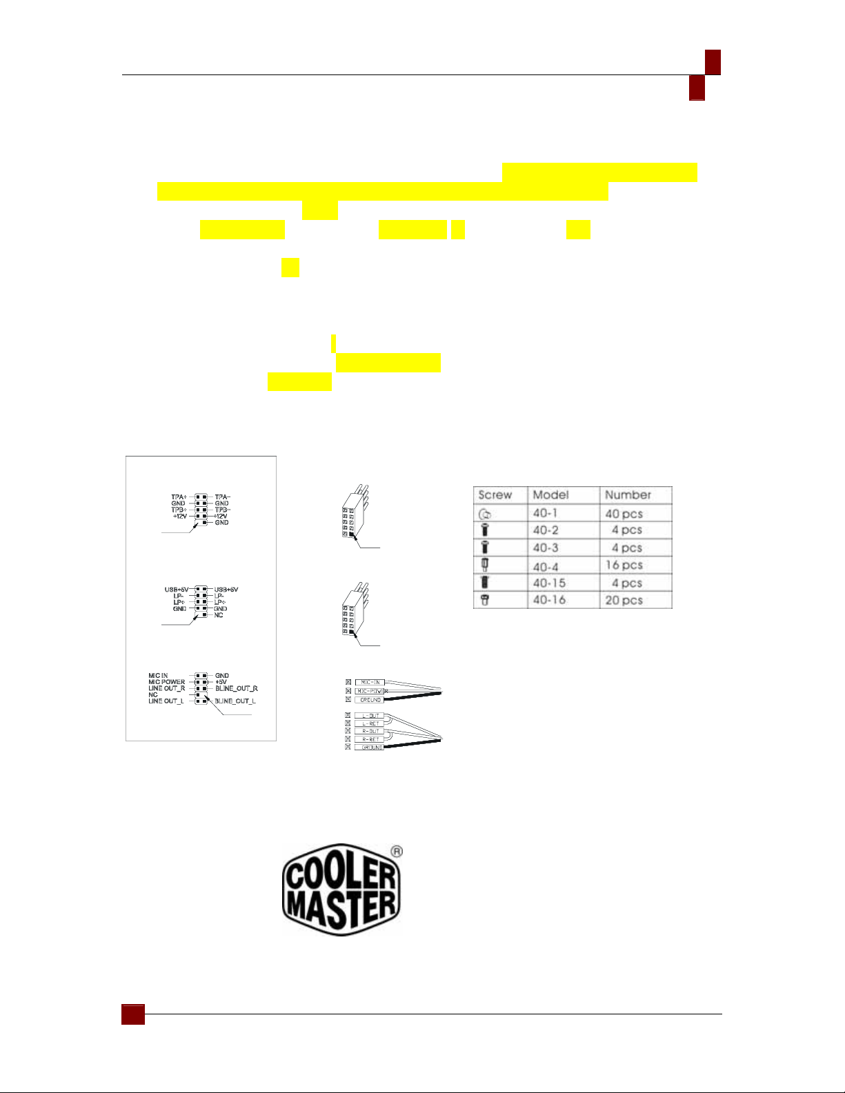
The following illustration is a connection diagram for the front panel I/O cable.
NEVER connect an IEEE1394 cable to the USB2.0 connector. Doing so will
damage the device.
NEVER connect a USB2.0 cable to the IEEE1394 connector. Doing so will
damage the device.
On some motherboards, the connectors for IEEE1394, USB2.0 and Audio
are not the same as the drawing below. Please check with your motherboard
manual before installing.
IEEE 1394 Connector
USB Connector
Front panel audio connector (BLACK)
Front panel USB connector
No Pin
Front panel audio connector
No Pin
Pin
Front panel IEEE 1394 connector
Mother Board
No Pin
Cable
Pin
IEEE 1394 Connector
USB Connector
Front panel audio connector (BLACK)
Front panel USB connector
No Pin
Front panel audio connector
No Pin
Pin
Front panel IEEE 1394 connector
Mother Board
No Pin
Cable
Pin
IEEE 1394 Connector
USB Connector
Front panel audio connector (BLACK)
Front panel USB connector
No Pin
Front panel audio connector
No Pin
Pin
Front panel IEEE 1394 connector
Mother Board
No Pin
Cable
Pin
Appendix
Contact us:
www.coolermaster.com
Email: info@coolermaster.com.tw
Headquarters, Taiwan
Tel: +886 2 32340050
Fax: +886 2 32340221
6
Table of contents
Other Cooler Master Desktop manuals