9
•
Прибор не предназначен для использования лица-
ми (включая детей) с пониженными физическими,
сенсорными или умственными способностями, или
при отсутствии у них жизненного опыта или знаний,
если они не находятся под присмотром или не про-
инструктированы об использовании прибора лицом,
ответственным за их безопасность.
•
Запрещается использовать кондиционер при
повреждении шнура питания или вилки шнура пита-
ния, если кондиционер работает с перебоями, после
его падения или иного повреждения.
•
При повреждении шнура питания его замену во избе-
жание опасности должны производить изготовитель,
сервисная служба или подобный квалифицирован-
ный персонал.
•
Запрещается самостоятельно ремонтировать прибор.
Не разбирайте прибор самостоятельно, при возникно-
вении любых неисправностей, а также после падения
устройства выключите прибор из розетки и обратитесь
в любой авторизованный (уполномоченный) сервис-
ный центр по контактным адресам, указанным в гаран-
тийном талоне и на сайте www.coolfort.ru.
•
Перевозите устройство в заводской упаковке.
•
Храните устройство в сухом прохладном месте, недо-
ступном для детей и людей с ограниченными воз-
можностями.
ДАННЫЙ ПРИБОР ПРЕДНАЗНАЧЕН ДЛЯ ИСПОЛЬЗОВА-
НИЯ ТОЛЬКО В БЫТОВЫХ УСЛОВИЯХ. ЗАПРЕЩАЕТСЯ
КОММЕРЧЕСКОЕ ИСПОЛЬЗОВАНИЕ И ИСПОЛЬЗОВА-
НИЕ ПРИБОРА В ПРОИЗВОДСТВЕННЫХ ЗОНАХ И РАБО-
ЧИХ ПОМЕЩЕНИЯХ.
ПОДГОТОВКА ПЕРЕД ИСПОЛЬЗОВАНИЕМ
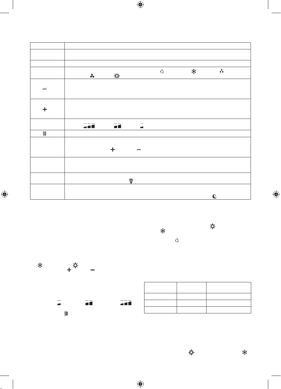
Пульт дистанционного управления (10)
Пульт дистанционного управления передаёт сигналы
управления в систему.
Установка элементов питания
–
Снимите крышку батарейного отсека в направлении
стрелки.
–
Вставьте новые батарейки, убедившись, что (+) и (-)
батареек правильно совмещены.
–
Установите крышку и сдвиньте её на место (рис. 1).
Примечание:
–
Используйте 2 батарейки AAA (1,5 В). Не используйте
аккумуляторные батареи. Замените батарейки на
новые, того же типа, когда дисплей станет тусклым.
–
Не допускается использовать одновременно батарей-
ку, выработавшую ресурс, и новую, а также батарейки
разных типов. Срок службы батареек не более 1 года.
–
Если вы не собираетесь использовать пульт дистан-
ционного управления длительное время, извлеките
батарейки и храните пульт с батарейками отдельно,
в безопасном и сухом месте.
ПЕРЕД ИСПОЛЬЗОВАНИЕМ КОНДИЦИОНЕРА ОБЯ-
ЗАТЕЛЬНО ПРОВЕРЬТЕ И НАСТРОЙТЕ СЛЕДУЮЩЕЕ:
Предварительная настройка пульта
дистанционного управления (ПДУ)
–
Пульт дистанционного управления (10) НЕ настроен
производителем на охлаждение или нагрев.
–
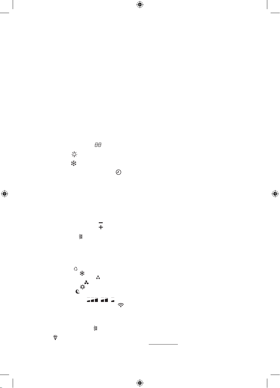
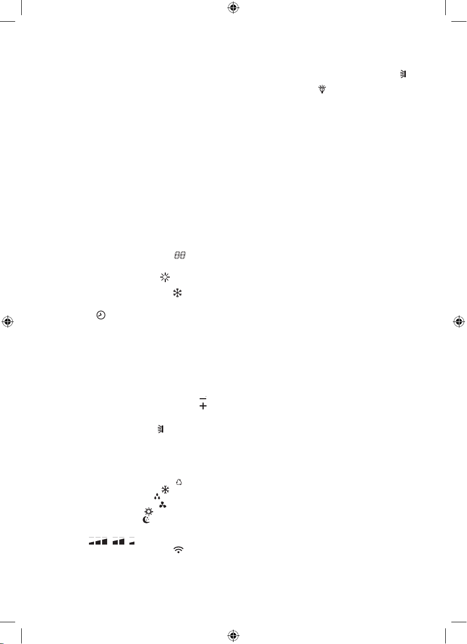
Каждый раз после замены батареек в ПДУ или при
включении питания, на дисплее пульта будет мигать
символ нагрева (36) « » или символ охлаждения
(33) « ».
Пользователь может предварительно настроить ПДУ
следующим образом:
–
Если вы нажмете любую кнопку ПДУ, когда мигает
символ нагрева (36) « », будет выбран режим
нагрева.
–
Если вы нажмете любую кнопку ПДУ, когда мигает
символ охлаждения (33) « », будет установлен
режим охлаждения.
Если вы не будете нажимать ни на одну кнопку в течение
10 секунд, пульт дистанционного управления автомати-
чески настроится на режим нагрева.
Предварительная настройка
автоматического перезапуска
Примечание: Автоматический перезапуск после сбоя и
последующего восстановления подачи электропитания
возобновляет работу системы с теми же параметрами,
что и до отключения.
Предварительная настройка функции
автоматического перезапуска с помощью
кнопки аварийного управления (21)
Прибор не настроен производителем на функцию авто-
матического перезапуска.
Если требуется функция автоматического перезапуска,
выполните следующие действия, чтобы активировать
эту функцию:
1) Убедитесь, что кондиционер выключен;
2) Нажмите и удерживайте аварийную кнопку (21) на
внутреннем блоке до включения кондиционера.
3) Продолжайте удерживать нажатой аварийную кнопку
(21) более 10 секунд, пока не услышите три коротких
звуковых сигнала.
После этого активируется функция автоматического
перезапуска. Чтобы отменить функцию автоматическо-
го перезапуска, повторите вышеуказанную процедуру,
пока не услышите четыре звуковых сигнала.
Предварительная настройка функции
автоматического перезапуска с помощью ПДУ
Производитель предварительно настроил устройство на
функцию автоматического перезапуска.
Если функция автоматического перезапуска не требуется,
выполните следующие шаги, чтобы отменить эту функцию:
1) Убедитесь, что кондиционер включен;
2) Нажмите кнопку (31) «SLEEP» 10 раз в течение
8 секунд, пока не прозвучат 3 коротких звуковых
сигнала.
После этого функция автоматического перезапуска
отменится. Чтобы активировать функцию автоматиче-
ского перезапуска, повторяйте описанную выше проце-
дуру до тех пор, пока не услышите 4 коротких звуковых
сигнала.
ПУЛЬТ УПРАВЛЕНИЕ КОНДИЦИОНЕРОМ
Для управления кондиционером применяется пульт дис-
танционного управления (10) ПДУ.
•
Чтобы управлять комнатным кондиционером,
направьте пульт дистанционного управления на окно
приёмника сигнала внутреннего блока (19).
•
При управлении, расстояние между пультом и вну-
тренним блоком кондиционера должно быть не боль-
ше 7 метров.
•
В момент передачи сигнала между пультом и вну-
тренним блоком не должно быть никаких препят-
ствий, мешающих прохождению сигнала.
•
Пульт управления должен находиться на расстоянии
не менее 1 метра от телевизионной и радиоаппа-
ратуры.
•
Не роняйте и не ударяйте пульт, а также не оставляйте
его под прямыми солнечными лучами.