Coolingstyle Technology TSC2-M028Y4 Installation instructions

TSC2-M028Y4 USER INSTRUCTION
Shenzhen Coolingstyle Technology Co., Ltd.

CONTENT
1. BASIC PARAMETERS.......................................................................................................................................3
2. COOLING CAPACITY CURVE........................................................................................................................4
3. FACTORY LIST.................................................................................................................................................. 4
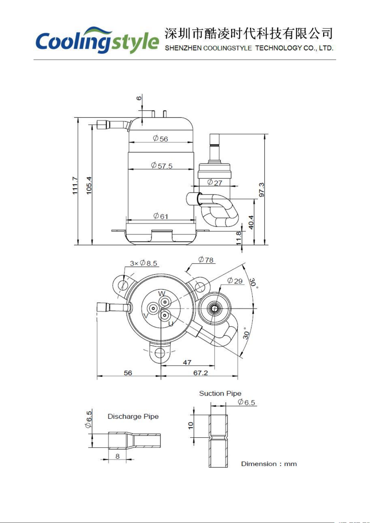
4. SIZE...................................................................................................................................................................... 5
4.1 COMPRESSOR SIZE....................................................................................................................................... 5
4.2 DRIVE BOARD SIZE...................................................................................................................................... 6
4.3 SIZE OF CUSHION.........................................................................................................................................6
4.4 INSTALLATION............................................................................................................................................. 7
5. DRIVER WIRING INSTRUCTIONS................................................................................................................ 8
5.1 POWER INPUT PORT(TB1, TB2)............................................................................................................. 8
5.2 WIRING PORT OF DRIVER AND COMPRESSOR(TB3, TB4, TB5)..............................................................8
5.3 CONDENSING FAN POWER SUPPLY PORT(TB6, TB7)..............................................................................9
5.4 INDICATOR...................................................................................................................................................9
5.5 5V VOLTAGE OUTPUT PORT (TB8).............................................................................................................10
5.6 COMPRESSOR SPEED SIGNAL INPUT PORT (TB9)....................................................................................... 10
5.7 COMPRESSOR ENABLE SIGNAL INPUT PORT (TB10).................................................................................. 10
5.8 GND(TB11).........................................................................................................................................10
5.9 STATUS SIGNAL OUTPUT PORT (TB12)...................................................................................................... 10
5.10 POWER SIGNAL OUTPUT PORT(TB13)...................................................................................................11
5.11 RESERVED EMERGENCY STOP SWITCH SIGNAL (TB14, TB15)................................................................... 11
5.12 RESERVED COMMUNICATION PORTS (TB16, TB17, TB18, TB19).............................................................11
6. TYPICAL WIRING EXAMPLE.......................................................................................................................12
6.1 EXAMPLE 1................................................................................................................................................12
6.2 EXAMPLE 2................................................................................................................................................13
6.3 EXAMPLE 3................................................................................................................................................14
7. NOTICE..............................................................................................................................................................15
8. TROUBLE SHOOTING....................................................................................................................................17

1. Basic Parameters
Compressor Type
DC Dual Rotor Inverter Compressors
Rated Voltage
DC 24V
Voltage range
24V±10%
Rated Current
12A
Maximum Current
16A
Displacement
2.8cm³/rev
Cylinder Number
2
Motor Rotor Pole
6
Maximum Compression Ratio
6
Speed Range
1800~4500rpm
Cooling Capacity(at 4500 rpm)
465W(ASHRAE Conditions)
Refrigerant
R134a
Max. Amount of Refrigerant
110g
Oil
RL68H
Oil Charge
50mL
Ambient Temperature
-5~55℃
Evaporating Temperature
-10~15℃
Condensing Temperature
45~76℃
Weight
1.3kg
Suction Tube(I.D)
6.5mm
Discharge Tube(I.D)
6.5mm

2. Cooling Capacity Curve
Test conditions: Condensing temperature: 54.4℃; Subcooling degree: 8.3℃; Ambient
temperature: 35℃
3. Factory list
NO.
Name
Unit
Qty.
1
Compressor
unit
1
2
Drive board
unit
1
3
Connect wire
pcs
1
4
Cushion
unit
3
5
Metal pillar
unit
3
6
Gasket
unit
3

4. Size
4.1 Compressor size

4.2 Drive board size
4.3 Size of cushion

4.4 Installation

5. Driver wiring instructions
Compressor TSC2-M028Y4 must be driven by a matched driver. The driver interface is shown
in the figure below.
5.1 Power input port(TB1, TB2)
The driver input voltage range is 24V±10%, port TB1 is positive and TB2 is negative.
5.2 Wiring port of driver and compressor(TB3, TB4, TB5)

The driver and the compressor are connected by a dedicated three-core cable, the colors of the
three-core cables are black, red, and white. The black wire is connected to port TB3; the red wire is
connected to port TB4; the white wire is connected to port TB5. The other end of the three-core wire
has been connected to the terminal block. The terminal block is buckled on the 3 terminal posts on
the top of the compressor without distinguishing the position.
5.3 Condensing fan power supply port(TB6, TB7)
The driver is equipped with ports TB6 and TB7 dedicated to supply power to the condensing fan,
where TB6 is the negative pole and TB7 is the positive pole. This port has voltage output only when
the compressor is running, the output voltage is 24V, and the maximum load is 2A.
5.4 Indicator
There are two indicators on the driver, the green one is the power indicator, and the red one is
the status indicator. The power indicator indicates the power status of the driver, and it will light up
as long as the power is connected. The status indicator indicates the compressor's working or fault
status. The specific description is shown in the table below.
Working/fault status
Description
Status indicator lighting
Normal work
No light
Waiting to start
The driver is connected to power, but the compressor does
not start.
Flashing at a constant
speed
Driver overvoltage
The high voltage protection is triggered when the input
voltage of the driver is higher than 32V, and returns to
normal when the voltage drops to 31.5V.
2 flash repeating
Driver undervoltage
When the driver input voltage is lower than 19V, the
low-voltage protection is triggered, and it returns to
normal when the voltage rises to 20.5V.
3 flash repeating
Driver overheating
The overheating protection is triggered when the
temperature of the driver exceeds 80 °C, and returns to
normal when the temperature drops to about 71°C.
4 flash repeating
Driver failure
The internal circuit of the drive is faulty.
6/7/8 flash repeating
External fault
Such as compressor stall, phase line short circuit, etc.
Light is always on

The status of the power indicator and the status indicator can be synchronously output through
ports TB13 and TB12, respectively.
5.5 5V voltage output port (TB8)
When the driver is connected to the power supply, the port TB8 can output a voltage of 5V,
which can be used to adjust the compressor speed, which will be described in detail later.
5.6 Compressor speed signal input port (TB9)
TB9 is a signal input port for controlling the speed of the compressor, which can receive voltage
signals, and the range is 0~5V (relative to GND). The corresponding relationship between voltage
value and compressor speed is shown in the following table (there may be some individual
differences).
Speed voltage U/V
Compressor speed N/rpm
0~1.35
0
1.35
1800
1.35<U<3.4
1300*(U-1)+1345
3.4≤U≤5
4500
5.7 Compressor enable signal input port (TB10)
The compressor can be started only when the compressor enable signal input port TB10 is
grounded (TB11). When TB10 is connected to high level or suspended, the compressor does not
work.
5.8 GND(TB11)
TB11 is connected to the negative port TB2 of the power supply, and is mainly used to connect
the control signal of the compressor. All voltage signals on the driver are relative to GND. If an
external circuit is used to control the compressor, the external circuit must also share the ground with
the driver.
5.9 Status signal output port (TB12)

TB12 can output voltage signal, synchronized with the status indicator. When the status
indicator (red light) is on, the voltage of TB12 is 2V; otherwise, there is no output.
5.10 Power signal output port(TB13)
TB13 can output power signal, synchronized with the power indicator. When the power
indicator (green light) is on, the voltage of TB13 is 2V; otherwise, there is no output.
5.11Reserved emergency stop switch signal (TB14, TB15)
The function of TB14 is the same as TB10. The compressor can only work when TB14 is
grounded. Under normal circumstances, it is not necessary to use this port to control the compressor's
working status, directly short-circuit it with TB15 (GND), and control the compressor through TB10.
Under special circumstances, an emergency stop switch can be connected between TB14 and TB15
to quickly start or stop the compressor.
5.12 Reserved communication ports (TB16, TB17, TB18, TB19)
TB16, TB17, TB18, TB19 are spare ports, and users can customize communication functions
through these ports.

6. Typical wiring example
6.1 Example 1
The two enable signals can be directly grounded, and the 5V voltage port TB8 on the driver and
the speed signal input port TB9 can be directly short-circuited to make the compressor always work
at the maximum speed. This wiring method cannot adjust the compressor speed, the wiring diagram
is as follows:

6.2 Example 2
On the basis of example 1, connect a 20K potentiometer between the +5V signal and the speed
signal on the driver, and adjust the compressor speed by adjusting the potentiometer, as shown in the
figure below.

6.3 Example 3
Users can also use an external 0~5V voltage signal to control the compressor speed without
using the +5V output voltage on the driver, as shown in the figure below. The voltage signal must
share the ground with the driver. A switch or control program can be used to control the start and stop
of the compressor by connecting or disconnecting the enable signal port TB10 and GND.

7. Notice
1. The compressor needs to be placed horizontally during operation, the maximum inclination
angle cannot exceed 15°, and it cannot be inclined for a long time.
2. The compressor should not be tilted or turned upside down during storage and transportation
to prevent oil overflow.
3. The compressor has been pre-filled with about 50cc of RL68H lubricating oil before leaving
the factory, which is sufficient for general refrigeration systems. For systems that have been
charged and discharged with refrigerant for many times, appropriate amount of lubricant of
the same type can be added as appropriate.
4. R134a must be used as a refrigerant.
5. When working, the driver should be installed in a location where it can easily dissipate heat.
6. Under any working conditions, the compression ratio of the compressor should be less than
6.
7. When the compressor starts, the pressure difference △P (discharge chamber
pressure-suction chamber pressure) should be below 0.03MPa. After the compressor stops,
you need to wait at least 30 seconds, and then start again after the pressure is balanced.
8. In order to protect the compressor, neither the rising rate nor the falling rate of the rotation
speed should exceed 120rpm/s.
9. Depending on the different refrigeration system, the refrigerant charge should be between
60~120g, and the maximum should not exceed 130g.
10. The driver current should not exceed 15A, if it exceeds this value, it should stop working
immediately.
11. Before charging the refrigerant, the internal pressure of the refrigeration system should be
less than 20Pa, and the water content should be less than 40ppm. There should be no
impurities, metal powders, and residual acids, alkalis, oils and cleaning agents in the
manufacturing process in the refrigeration accessories and pipelines. During brazing, a
shielding gas should be injected into the system to prevent the occurrence of oxide scale.
12. It is absolutely forbidden to operate the compressor with air or a mixture of air and working
fluid, as this may cause an explosion.

13. The suction pipe and exhaust pipe of the compressor are blocked with blind plugs, and they
are allowed to be unplugged during use. After removing the blind plug, the inside of the
compressor should not be exposed to the atmosphere for more than 5 minutes.
14. Before removing the blind plug, it is allowed to run the compressor directly for a short time
to see if it is normal. After the refrigeration system is vacuumed, the compressor cannot be
operated directly if the refrigerant has not been charged.
15. The wiring must be carried out in strict accordance with the wiring instructions, and the
three phase wires of the compressor U, V and W cannot be connected wrongly. If it is
connected incorrectly, the compressor may reverse and the compressor cannot be used after
the reverse.
16. Do not keep the speed signal between 0.8V and 1.2V for a long time. In this interval, the
compressor may be damaged due to repeated start and stop.
17. The maximum output power of the driver's 24V power supply should not be less than 350W.

8. Trouble Shooting
Symptom
Possible Causes
Method
The speed
control signal is
normal but the
compressor
does not rotate
1 or 2 of the 2 enable signals are not
grounded
Speed control voltage is lower than 1.35V
Loose wiring
Insufficient power, sudden voltage drop at
startup
Compressor enters locked protection state
Check the enable signal
Check the speed signal
Check whether the wiring sequence of the compressor
and the driver is correct, and whether the wiring is loose
Check the output power of the power supply; check
whether the power supply voltage falls below the
minimum allowable voltage (especially at the moment of
starting)
Judge the cause of fault protection by flashing red LED
The compressor
stops working
instantly
Driver overheat protection
Loose wires or terminals
Insufficient power supply (pay special
attention to the battery)
Judge the cause of fault protection by flashing red LED
Check whether the wire or terminal is loose
Check whether the power supply is insufficient
Compressor
speed jump
The driver enters current protection mode
The driver is close to high temperature
protection
Check the flashing of the LED indicator to determine the
fault status
Compressor
overheated
The ambient temperature is too high
No air flow or insufficient air flow above
the compressor
Return air temperature is too high
Enhance the airflow above the compressor
Check the degree of superheat, it is recommended to set
the degree of superheat between 4-6℃
Compressor
overcurrent
The condensing pressure is too high
Compressor liquid hammer
Reduce condensing temperature/pressure
Check the degree of superheat, it is recommended to set
the degree of superheat between 4-6℃

Shenzhen Coolingstyle Technology Co., Ltd.
Add: BLDG H, Gangzhilong Technology Center, Longhua Area, Shenzhen, Guangdong, China.
Tel: +8613016488084
Website: www.coolingstyle.com
Email:[email protected]
Table of contents
Popular Air Compressor manuals by other brands

ABB
ABB Aztec ADS430 EZCLEAN operating instructions

Elektra Beckum
Elektra Beckum Compressor Pump Mega 500 W operating instructions

Heavy Duty Power Systems
Heavy Duty Power Systems HD5510TH owner's manual

Westfalia
Westfalia 6825 instruction manual

GEA
GEA HGX7 R134a Assembly instructions

BLACKMER
BLACKMER HD161A Installation, operation & maintenance instructions

HARDER & STEENBECK
HARDER & STEENBECK 20A operating instructions

Air Liquide
Air Liquide CP 40R 6M Safety instruction for use and maintenance

Porter-Cable
Porter-Cable CPF23400S instruction manual

Drive Medical
Drive Medical Drive CHAD 50 Patient instructions

Reddot
Reddot 12VDC installation instructions

Panasonic
Panasonic DA66C10RCU6 Specification sheet