MIL'S 15SP1CB User manual


Specifications are subject to change without notice.
This document may not be forwarded or reproduced without authorisation from MIL’S SAS company.
Failure to respect this requirement may lead to prosecution.
SCROLL 15SP1CB / 13SP2CB –35SP1CB / 29SP2CB –52SP1CB / 42SP2CB
520606-00 1
EN
CONTENTS
1GENERAL INFORMATION ............................................................................................................................ 2
2MAIN COMPONENTS .................................................................................................................................. 2
3MAINTENANCE OF THE AIR-END................................................................................................................. 3
3.1 Disassembly of the air-end ...................................................................................................................................................3
3.2 Disassembly of the tip seals ..................................................................................................................................................5
3.3 Supplying grease into the bearings.......................................................................................................................................5
3.4 Replacement of the brush [only for 52SP1CB / 42SP2CB] ....................................................................................................8
3.5 Assembly of the air-end ........................................................................................................................................................9
3.6 Cleaning the suction filter or replacement .........................................................................................................................12
3.7 Re-tightening discharge piping ...........................................................................................................................................12
4OTHERS .....................................................................................................................................................13
MEANING OF SYMBOLS USED IN THIS MANUAL
Symbols are used in this manual to help you understand them and to indicate particular points which you need to act upon or
consider. Those symbols are:
Reading symbol: to refer to the operator manual / instructions manual.
Warning symbol: This symbol means that failure to observe this point could lead to injury and possibly damage to
the machine. It serves as a special reminder about regulations and/or the correct implementation of certain
precautions.
Danger symbol: This symbol represents the DIN 4844 symbol (hazard warning); it warns of a hazard which could
result in death or injury, along with damage to the machine. This symbol must be observed by all personnel working
on this machine. Regulations on safety in the workplace must be observed.
Environmental protection symbol: This symbol serves as a reminder to sort waste during maintenance operations,
to store it in a safe place, and to dispose of it with due care for the environment.
Dustbin on wheels barred of a cross symbol: This symbol indicates that the equipment should not be thrown with
domestic waste and is subject to selective collection.
It is formally forbidden to take off the adhesive labels being on this machine.
The deteriorated adhesives or falling apart will have to be replaced.
General remark:
If they are used as the manufacturer intended, machines bearing marking comply with the requirements of the machines
directive 2006/42 EEC.
To ensure personal safety and to avoid any damage to equipment, it is essential to follow the instructions
contained in this document and any other documentation provided with the device, and particularly the
instructions on “Safe Practice”.
SCROLL 15SP1CB / 13SP2CB –35SP1CB / 29SP2CB –52SP1CB / 42SP2CB
2 520606-00
EN
1GENERAL INFORMATION
Make sure to service and maintain a product indoor to prevent dust from damaging the product.
Make sure not to blow bearing directly.
Make sure not to put cloth gloves in servicing and maintaining a product to prevent clothing from entering into bearings.
Don’t hit any part of an scroll head in removing a fixed scroll from the scroll head.
Cleaning inside of auxiliary parts for dust and particle not to flow back to a Scroll head.
Make sure not to replace parts except face seal and tip seals.
Use metric tools when disassembling and/or assembling scroll head.
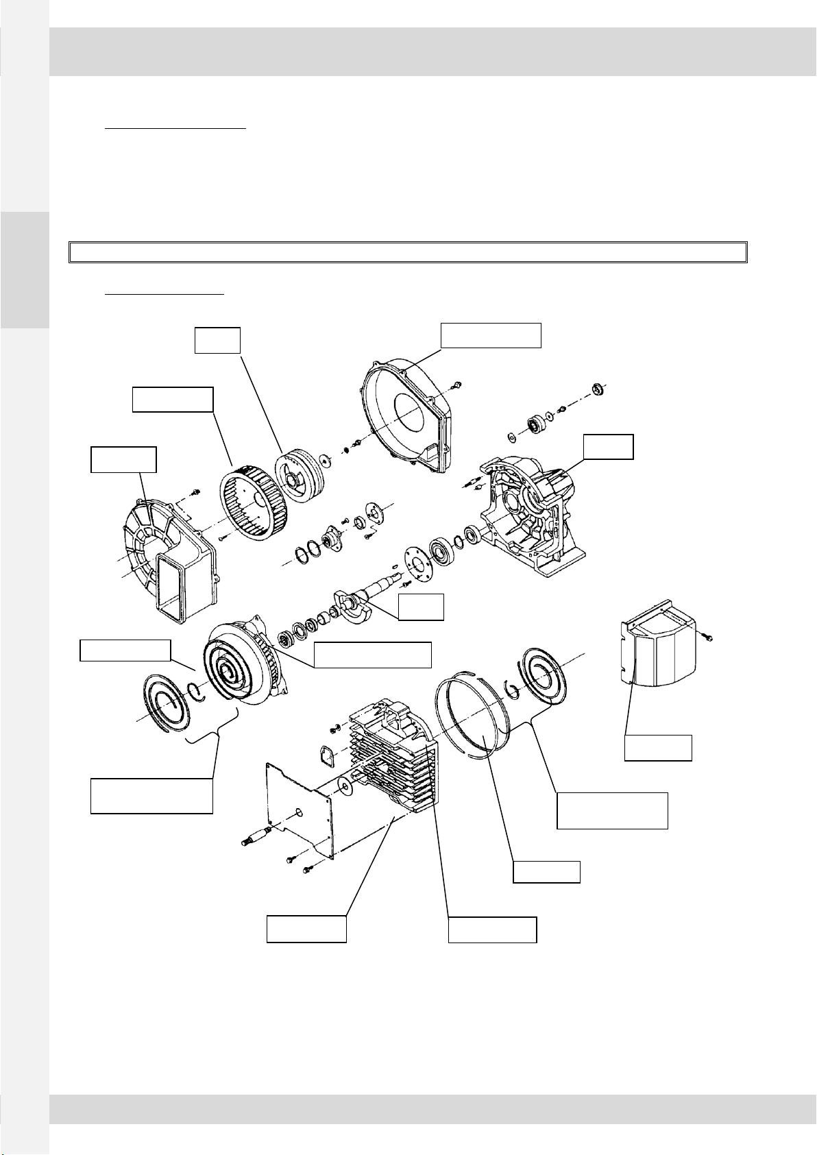
2MAIN COMPONENTS
Shaft
Fan Duct Guard
Pulley
Cooling Fan
Fan Duct
Tip Seal for Orbiting
Scroll
Orbiting Scroll
Casing
Side Duct
Tip Seal for Fixed
Scroll
Face Seal
Fixed Scroll
Main Shaft Bearing
Back-up tube
SCROLL 15SP1CB / 13SP2CB –35SP1CB / 29SP2CB –52SP1CB / 42SP2CB
520606-00 3
EN
3MAINTENANCE OF THE AIR-END
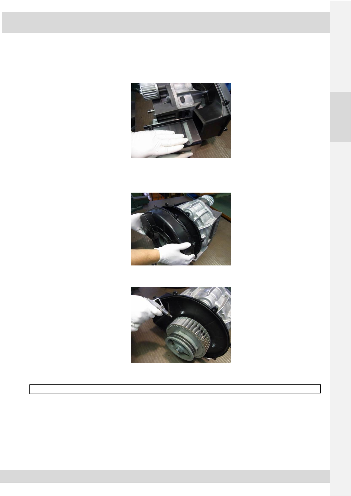
3.1 Disassembly of the air-end
1) Remove the side duct
2) Remove the fan duct cover
①15SP1CB / 13SP2CB: Take off 8 screws (6mm).
②35SP1CB / 29SP2CB - 52SP1CB / 42SP2CB: Take off 9 screws (6mm).
3) Clean the cooling fan
①Blow off dust of the cooling fan by air blow.
②Blow off dust of the fixed and orbiting scroll fin.
Clean the cooling fan before disassembling the fixed scroll to prevent dust entering into compression area.

SCROLL 15SP1CB / 13SP2CB –35SP1CB / 29SP2CB –52SP1CB / 42SP2CB
4 520606-00
EN
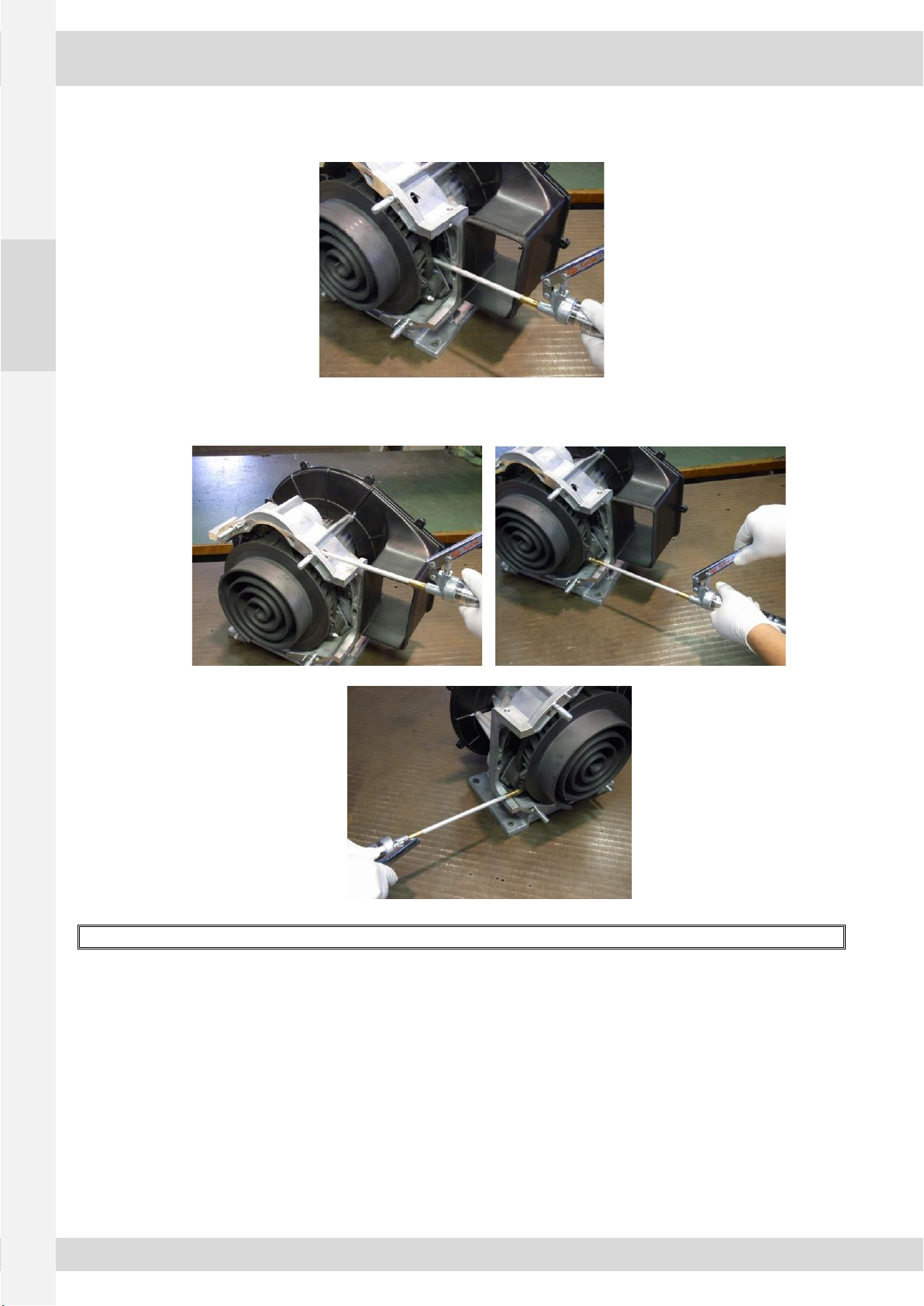
4) Disassembly the fixed scroll
Disassemble the fixed scroll after cooling enough to prevent difference of knock-pins pitch by thermal expansion
Note: It is easy to disassemble to put lubricant to knock-pin in advance
①Loose the 4 of nuts(M10) for 1 revolution.
It should be marked on the nut to count revolution.
②Disassemble the fixed scroll keeping parallel with the fixed scroll and frange surface of casing using plastic hammer.
Knock the fixed scroll gently when using plastic hammer.
③Repeat ①through ③until taking off the fixed scroll from casing.(7 times)
Do not damage scroll wrap during and after removing the fixed scroll.

SCROLL 15SP1CB / 13SP2CB –35SP1CB / 29SP2CB –52SP1CB / 42SP2CB
520606-00 5
EN
3.2 Disassembly of the tip seals
Do not damage scroll wrap when disassembling the tip seals and face seal, back-up tube.
3.3 Supplying grease into the bearings
Supply grease into the main shaft bearing and 3 of support bearings.
①Take off the rubber plug.
SCROLL 15SP1CB / 13SP2CB –35SP1CB / 29SP2CB –52SP1CB / 42SP2CB
6 520606-00
EN
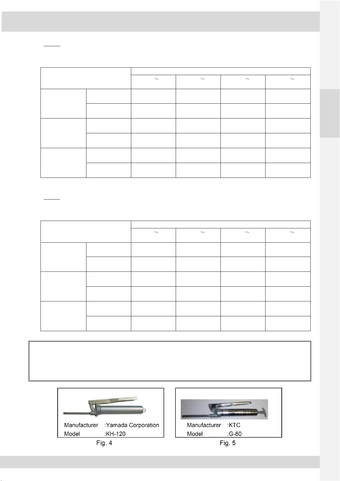
②Supply grease into the main shaft bearing using specified grease gun.
Refer to fig 4/5 for the grease gun and amount of supplying grease.
③Supply grease into the support bearings. (3 places)
Refer to fig 4/5 for the grease gun and amount of supplying grease.
Clean Up the head of grease nipples in case of dirty before supplying grease
SCROLL 15SP1CB / 13SP2CB –35SP1CB / 29SP2CB –52SP1CB / 42SP2CB
520606-00 7
EN
Table 1.
Amount of supplying grease
[0.83MPa use for 15SP1CB; 35SP1CB; 0.8MPa use for 52SP1CB]
Item
Amount of supplying grease
0h
2,500h
2,501h
5,000h
5,001h
7,500h
7,501h
10,000h
15SP1CB
Main shaft
bearing
5 strokes
(2.8±0.3 g)
9 strokes
(5.0±0.5 g)
13 strokes
(7.3±0.6 g)
15 strokes
(8.4±0.6 g)
Support bearings
(3 places)
1 stroke
(0.6±0.1 g)
2 strokes
(1.1±0.1 g)
3 strokes
(1.7±0.2 g)
4 strokes
(2.2±0.2 g)
35SP1CB
Main shaft
bearing
5 strokes
(2.8±0.3 g)
9 strokes
(5.0±0.5 g)
13 strokes
(7.3±0.6 g)
15 strokes
(8.4±0.6 g)
Support bearings
(3 places)
1 stroke
(0.6±0.1 g)
2 strokes
(1.1±0.1 g)
3 strokes
(1.7±0.2 g)
4 strokes
(2.2±0.2 g)
52SP1CB
Main shaft
bearing
5 strokes
(2.8±0.3 g)
11 strokes
(6.2±0.4 g)
16 strokes
(9.0±0.5 g)
22 strokes
(12.3±0.6 g)
Support bearings
(3 places)
1 stroke
(0.6±0.1 g)
2 strokes
(1.1±0.1 g)
3 strokes
(1.7±0.2 g)
5 strokes
(2.8±0.2 g)
Table 2.
Amount of supplying grease
[1.0MPa use for all models]
Item
Amount of supplying grease
0h
1,250h
1,251h
2,500h
2,501h
3,750h
3,751h
5,000h
13SP2CB
Main shaft
bearing
5 strokes
(2.8±0.3 g)
9 strokes
(5.0±0.5 g)
13 strokes
(7.3±0.6 g)
15 strokes
(8.4±0.6 g)
Support bearings
(3 places)
1 stroke
(0.6±0.1 g)
2 strokes
(1.1±0.1 g)
3 strokes
(1.7±0.2 g)
4 strokes
(2.2±0.2 g)
29SP2CB
Main shaft
bearing
5 strokes
(2.8±0.3 g)
9 strokes
(5.0±0.5 g)
13 strokes
(7.3±0.6 g)
15 strokes
(8.4±0.6 g)
Support bearings
(3 places)
1 stroke
(0.6±0.1 g)
2 strokes
(1.1±0.1 g)
3 strokes
(1.7±0.2 g)
4 strokes
(2.2±0.2 g)
42SP2CB
Main shaft
bearing
5 strokes
(2.8±0.3 g)
11 strokes
(6.2±0.4 g)
16 strokes
(9.0±0.5 g)
22 strokes
(12.3±0.6 g)
Support bearings
(3 places)
1 stroke
(0.6±0.1 g)
2 strokes
(1.1±0.1 g)
3 strokes
(1.7±0.2 g)
5 strokes
(2.8±0.2 g)
Note:
1) Use grease gun as shown in Fig 4 or 5 when supplying grease into each bearings.
2) Do not supply grease into each bearings beyond specified number show in above table, otherwise the bearings are damaged.
3) The amount of supplying grease should be determined based on operating time mentioned below.
1st time: Operating time from start operation
2nd time: Operating time from the last time maintenance
SCROLL 15SP1CB / 13SP2CB –35SP1CB / 29SP2CB –52SP1CB / 42SP2CB
8 520606-00
EN
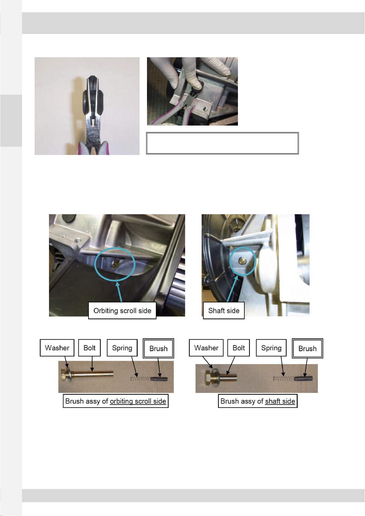
④Assemble the rubber plug using a plier.
3.4 Replacement of the brush [only for 52SP1CB / 42SP2CB]
①Remove brushes each of orbiting scroll side and shaft side.
②After that, replace brushes and re-assemble.
③Do not lose a washer.
④Tighten torque of the bolt: 15 N-m
Pull out the plier pressing the rubber plug by finger.
SCROLL 15SP1CB / 13SP2CB –35SP1CB / 29SP2CB –52SP1CB / 42SP2CB
520606-00 9
EN
3.5 Assembly of the air-end
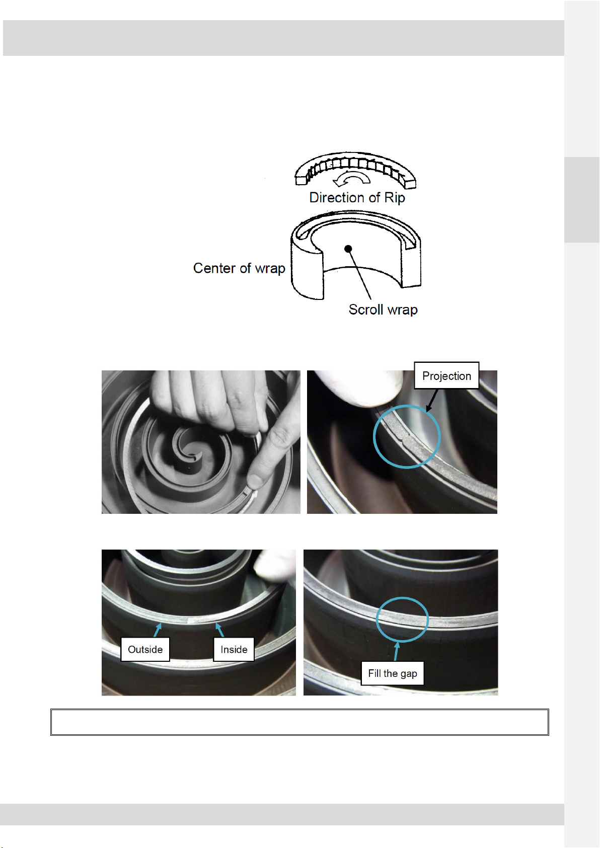
1) Install the tip seals and face seal
①Make sure to install tip seals in the right direction, because the orbiting scroll tip seals and the fixed scroll tip seals are
different.
②First, install outside tip seal.
Push the inner end of the outside tip seal to the outer end of the inside tip seal and then install the tip seal into the
groove.
Make sure that a stopper of the outside tip seal fits in a projection of the groove.
③Second, install inside tip seal filling the gap of outside and inside tip seals.
Do not push out the tip seals to bottom of groove.
Install tip seals to the groove by protruding 1mm from edge of groove
SCROLL 15SP1CB / 13SP2CB –35SP1CB / 29SP2CB –52SP1CB / 42SP2CB
10 520606-00
EN
④Install back-up tube and face seal
Move the seam of each seal 180 degrees.
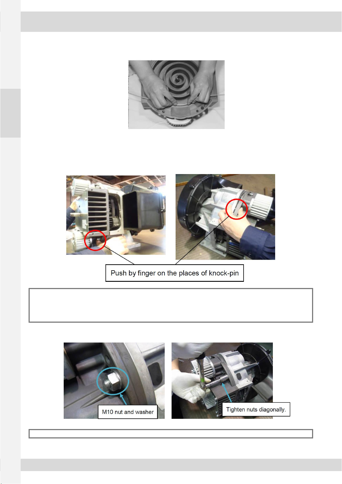
2) Assembly of the fixed scroll
①Assemble the fixed scroll on the basis of 2 places knock-pin.
Note for the direction of the fixed scroll.
②The gap of the fixed scroll and frange surface of casing should be below 2 mm.
If the gap between the fixed scroll and the casing is more than 2mm or is not parallel, there is a possibility that the tip seals or
face seal are not installed in the groove properly.
In this case, never tighten nuts and disassemble the fixed scroll and repeat the same
process to install the tip seals or seal properly.
③Tighten 4 of M10 nuts including washers.
First tighten nuts by hand and then tighten them at the equal torque of 30 N-m using a torque wrench.
SCROLL 15SP1CB / 13SP2CB –35SP1CB / 29SP2CB –52SP1CB / 42SP2CB
520606-00 11
EN
④After assembling the fixed scroll to the casing, turn the shaft by hand to confirm the smooth rotation of the shaft.
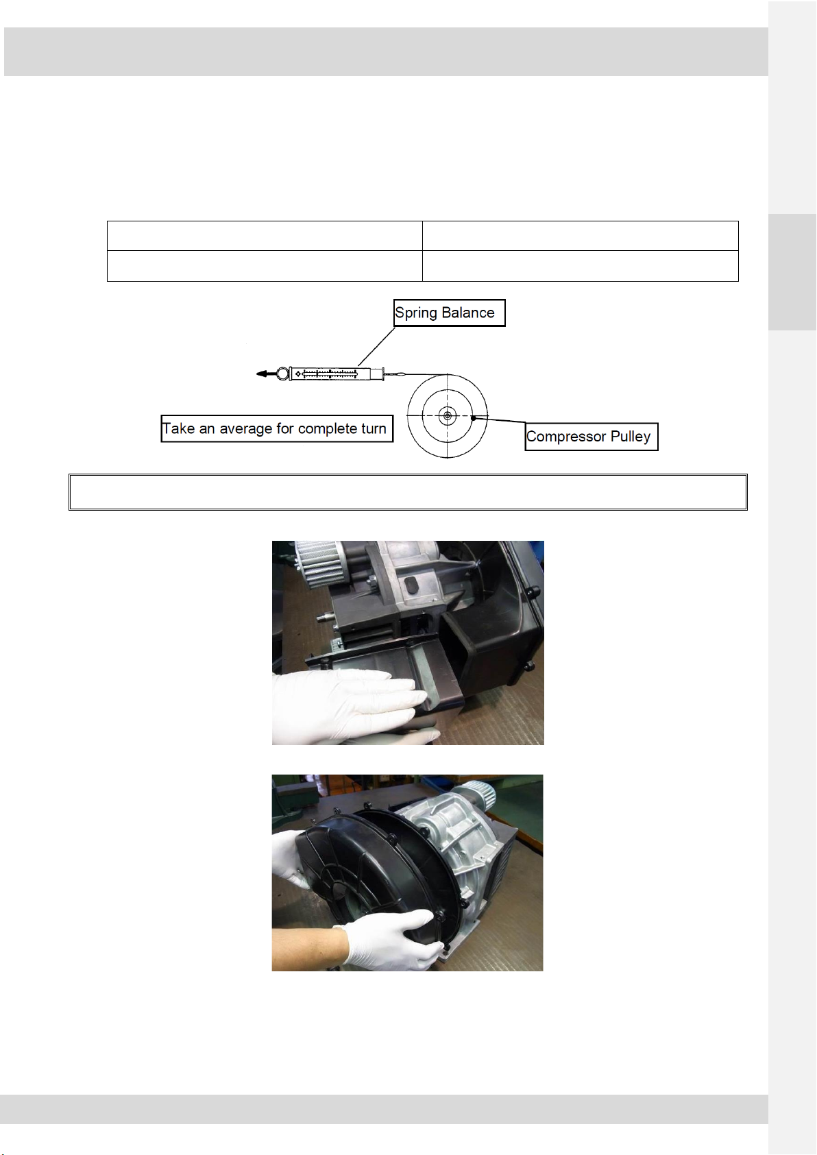
⑤Measure the torque of the shaft
After installing the fixed scroll, measure torque of the shaft.
Coil a piece of string around the pulley and then connect a spring balance to the another end of the string and then turn the
pulley more than one complete turn by pulling the spring balance. Take a measurement of the spring balance, and calculate
the average.
Model
Torque of the Shaft [Unit:1Kg]
15SP1CB/ 13SP2CB - 35SP1CB/ 29SP2CB
52SP1CB / 42SP2CB
Less than 2.2 Kg
If the rotation is hard at fixed angle during measuring the torque or rotation by hand, there is a possibility of misalignment.
In this case, the air-end must be replaced.
3) Assemble the side duct
4) Assemble the fan duct cover
SCROLL 15SP1CB / 13SP2CB –35SP1CB / 29SP2CB –52SP1CB / 42SP2CB
12 520606-00
EN
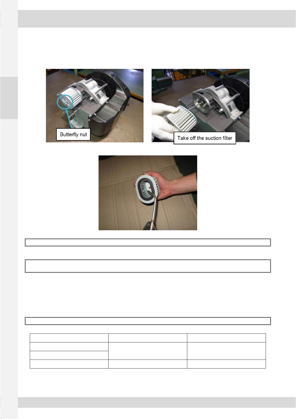
3.6 Cleaning the suction filter or replacement
1) Remove the suction filter
①Remove the butterfly nut, then remove the suction filter
2) Air blow from inside of suction filter
In case that the filter is very and/or damaged, replace to the new one.
3.7 Re-tightening discharge piping
Refer to the following procedure to re-tighten discharge piping after maintenance of air-end in case when removed the
discharge piping tentatively from the air-end during maintenance
Tighten the discharge pipe in the correct procedure as shown below.
1) Finger-tighten the discharge pipe till you cannot
At this stage, do not use the wrench.
2) Put a reference line on the discharge pipe to count turns.
3) Tighten the discharge pipe additional turns shown in table below using wrench.
Over tightening of discharge pipe will cause damage to screw thread of pipe and air-end.
Model
Nominal pipe diameter
Additional turns
15SP1CB / 13SP2CB
3/8B (10A)
4 to 4.5
35SP1CB / 29SP2CB
52SP1CB / 42SP2CB
1/2B (15A)
3 to 3.5

SCROLL 15SP1CB / 13SP2CB –35SP1CB / 29SP2CB –52SP1CB / 42SP2CB
520606-00 13
EN
4OTHERS
Inspection of the air-end
(1) Rotation of bearings
If the main shaft does not rotate smoothly, replace the air-end.
(2) Condition of scroll wrap is contacted each other and scratched, replace the scroll air-end.

www.mils.fr
This manual suits for next models
5
Table of contents
Other MIL'S Air Compressor manuals

Popular Air Compressor manuals by other brands

AirMan
AirMan PDS400S-6C3 Service manual

Mi-T-M
Mi-T-M ACD Series Operator's manual

Jefferson
Jefferson TANDEM JEFC270T10B-230 user manual

Doosan
Doosan 7/72 Operation and maintenance manual

Craftsman
Craftsman 919.16778 Operator's manual

Industrial Air Contractor
Industrial Air Contractor C042I Operator's & parts manual

Craftsman
Craftsman 919.725502 owner's manual

EINHELL
EINHELL EURO8/24 operating instructions

Kobalt
Kobalt 215914 manual

Bauer Compressors
Bauer Compressors Junior II WT Instruction manual and replacement parts list

Grizzly
Grizzly T32336 owner's manual

Schneider Airsystems
Schneider Airsystems CPM 210-8-10 WXOF Original operating manual


