Cooper Hand Tools Radio User manual

WR 3M - Operating Instructions 1 of 21
ENFRITESPTNLSVDKFIGRTRCZPLHUSKSLEELVLT
Device Overview
1 Channel Selection LED
Indicator
2 Heater Power LED Indicator
3 Vacuum “On” LED
4 LCD Display
5 UP Scroll Key
6 DOWN Scroll Key
7Channel Selection Radio
Buttons ┌ 1 ┐,┌ 2 ┐,┌ 3 ┐
8 Start/Stop Pick-Up Radio
Button
9 Status Display LED Pick-Up
10 Channel Selection Radio
Button ┌ 1·2·3 ┐
11 Hot-Air Setting Radio Button
(Air)
12 Power Switch
13 Pick-up Connections,
14 Vacuum Connection, (Vac)
15 Hot Air Connection, (Air)
16 Receptacle ┌ 1 ┐,┌ 2 ┐,┌ 3 ┐
17 Temperature Display
18 Temperature Symbol
19 Time Functions
20 Lock
21 Heater Control Indicator
22 Display, Channel Selection
23 Display, Fixed/Pre-Set
temperature
24 Display, Special Functions
25 USB port
26 Fuse
27 120 VAC Power Connection
28 N/A (US Versions)

Page 2 of 21 WR 3M
Table of Contents
1 Instructions 2
2 Cautions and Warnings 2,3
3 Packing List 3
4 Description 3,4
5 Initial Set-up 5
6 Operating Guidlines 6
7 Special Functions 8
8 Maintaining and Servicing the WR 3M 16
9 Fault Indications and Correction 17
10 Accessories 18
11 Disposal 19
12 Warranty 19
1Instructions
Thank you for placing your trust in our company by purchasing the
Weller WR 3M. This product meets or exceeds the requirements
established by Weller for superior performance, versatility and
quality.
These instructions contain important information which will help you
to start, operate and service the WR 3M Rework Station safely and
correctly, as well as eliminate simple faults/malfunctions yourself.
ZRead these instructions and the accompanying safety information
carefully before starting up the device and starting work with the
WR 3M Rework Station.
ZKeep these instructions in a place that is accessible to all users.
2Cautions! / Warnings!
Please read these Operating Instructions and the attached Safety
Information carefully prior to initial operation. Failure to observe the
safety warnings may result in accident, injury, or risk to health.
The manufacturer shall not be liable for damage resulting from
misuse or unauthorized alterations of the equipment.
Warning: This product when used for soldering and similar
applications, produces chemicals known to the State of California to
cause cancer and birth defects or other reproductive harm.

WR 3M Page 3 of 21
ENFRITESPTNLSVDKFIGRTRCZPLHUSKSLEELVLT
Safety Information:
z Always place the soldering iron in its original holder
z Remove all inflammable objects from the proximity of the hot
soldering tool.
z Use suitable protective clothing to prevent the risk of burns
associated with molten solder.
z Never leave a hot soldering iron unattended.
z Never work on electrically live circuits or components.
z Always wear eye protection when working with soldering and
desoldering applications.
The Weller WR 3M microprocessor-controlled Rework Station
corresponds to the EC Declaration of Conformity in accordance
with the basic safety requirements of Directives 89/336/EEC and
73/23EEC.
3Packing List
−WR 3M Rework Station
−Power cord
−Air-hose adapter for Hot-Air pencil (HAP 1)
−HAP 200 Hot Air Pencil ( WR3000M only )
−WDH 30 Tool Holder ( WR3000M only )
−WP80 Soldering Iron ( WR3000M only )
−WDH 10 Tool Holder ( WR3000M only )
−DXV 80 Desoldering Iron ( WR3000M only )
−WDH 40 Tool Holder ( WR3000M only )
−WR 3M Operating Instructions
−Safety information booklet
−CD with USB software (“Firmware Updater” and “Monitor
Software”)
−USB cable
−Packing with colored tool markers
4Description
The Weller WR 3M is a versatile Rework System for making
professional repairs to current technology electronic assemblies in
the industrial production and engineering sectors. The WR 3M has 3
independent channels for operating 3 tools simultaneously.
Fast and precise sensor sampling in the closed loop control provides
temperature accuracy and maximum temperature control under load.
All tools are recognized automatically by the WR3M and the
appropriate control parameters are set.

Page 4 of 21 WR 3M
The desired temperature can be adjusted in the range of 150°F to
999°F for hot-air tools and the WSP150 Soldering Iron; 150°F to
850°F for all other soldering / desoldering tools. Set and Read values
are displayed in digital form. Three Radio Buttons are used to select
fixed / pre-set temperatures directly. The Heater Control Indicator
("a“ symbol in the display), along with a green LED above the port
being monitored, flashes to indicate when the Set temperature has
been reached.
4.1 Tools and Holders
When not in use all tools should be placed in their proper Tool
Holder.
HAP 200: ( WR3000M )
The HAP 200 Hot Air Tools 200 watt heater produces a temperature
range of 122°F (50°C) to 1000°F (550°C). The integrated finger
switch and a wide assortment of nozzles make it suitable for multiple
applications, including soldering or desoldering surface mount
components using hot air. The ionizing circuit incorporated in the tool,
along with the antistatic handle and hose, provides static free hot air.
DXV 80: ( WR3000M )
The DXV 80 is an 80W Desoldering Tool with an in-line filter and an
eccentric taper lock system for the desoldering tiplet. The in-line
solder collection chamber is an integral part of the handle and can
easily be changed without the use of tools. This tool has a wide
range of available desoldering tiplets for multiple applications.
Vacuum is activated by depressing the finger switch located on the
handle.
WP 80: ( WR3000M )
The WP 80 Soldering Iron is characterized by fast heat-up and
precise control of the soldering tip. Due to its slim design, 80W heater
output and short reach ( tip to grip ), this tool can be used for a
variety of applications, from extremely fine soldering tasks to those
requiring high temperatures.
WDH 10 ; ( Tool Holder for WP 80 )
WDH 30 ; ( Tool Holder for HAP 200 )
WDH 40 ; ( Tool Holder for DXV 80 )
See ‘‘Accessories‘‘ for additional tools.

WR 3M Page 5 of 21
ENFRITESPTNLSVDKFIGRTRCZPLHUSKSLEELVLT
The Weller WR 3M Rework Station offers the following additional
features / functions:
−Automatic tool detection and activation of the related control
parameters
−Operates with all Weller tools listed in the Accessories section on
page 18
−Digital Temperature Control
−Temperature Offset
−Programmable Temperature (Setback)
−Standby and Lock functions
−Heavy-duty pump
−Antistatic device design in accordance with EOS / ESD safety
standards
−USB port for control, evaluation and documentation via PC
−Additional vacuum port for component handling (Pick-up)
4.2 WR 3M Technical Data
Dimensions L x W x H (inches): 10.75 x 9.25 x 4.02
Weight Approximately. 14.8 lbs.
Power supply voltage 120 VAC, 60 Hz
Power consumption 400 Watts
EOS / ESD Properties All Tool Handles, Cordsets and Air Flow
are Static Free
Fuse 4 Amp
Temperature Control
range
Variable in (1) degree increments from
150 °F – 999 °F
Controllable temperature range is tool-
dependent
Temperature accuracy ± 17 °F ( Average tip temperature can
be offset ± 9 °F at idle with no load )
Temperature stability ± 9 °F
Hot Air / Vacuum Pump
( duty cycle: 30 seconds
on - 30 seconds off )
Max. vacuum 0.7 bar
Max. delivery rate 18 l/min
Hot air max. 15 l/min
Vacuum Pick-Up Pump
( duty cycle: 60 seconds
on - 30 seconds off )
Max. vacuum 0.5 bar
Max. delivery rate 1.7 l/min
USB Port
The control unit is equipped with a mini USB port (25). Weller
software, included on a CD, provides station monitoring and control
via the USB port.
With the software you;
−can carry out a software update ("Firmware Updater“) on your
control unit.

Page 6 of 21 WR 3M
−can remotely control the unit and chart, store and print temperature
curves ("Monitor Software“).
5Initial Set-up
WARNING!
•Risk of injury may occur if vacuum hose is incorrectly
connected to the air port (15).
If the vacuum hose is incorrectly connected, hot air and liquid
solder can escape when the desoldering button is depressed and
may cause injuries.
ZNever connect the vacuum hose to the "Air“ port (15)!
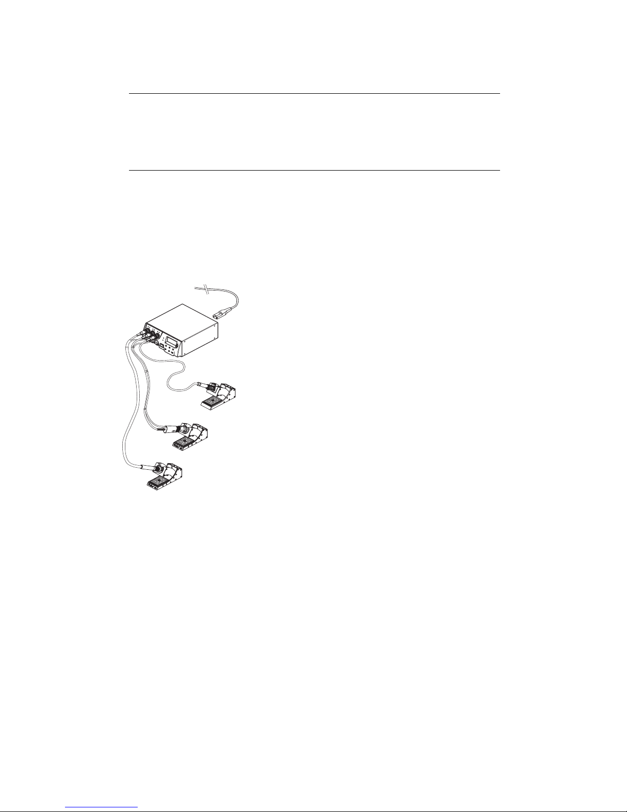
1. Carefully unpack the device.
2. Connect the soldering tools as follows:
-Connect the hot-air pencil (HAP200) with air hose to "Air“ port
(15) and insert the (HAP200) plug into the receptacle ┌ 1 ┐,
-(16) of the Rework Station and lock by turning clockwise slightly.
The hot-air pencil (HAP 1) can only be connected with the
supplied air-hose adapter.
Note: The HAP 200 will only operate when connected to channel 1!
-Connect the Desoldering tool (DXV80) with vacuum hose to
"Vac“ port (14) and insert the (DXV80) tool plug into the
receptacle ┌ 1 ┐, ┌ 2 ┐ or ┌ 3 ┐ (16) of the Rework Station and
lock by turning clockwise slightly.
-Connect the Soldering tool (WP80) with Soldering tool plug into
the receptacle ┌ 1 ┐, ┌ 2 ┐ or ┌ 3 ┐ (16) of the Rework Station
and lock by turning clockwise slightly. If using the optional
(WDH10T) Switching Holder with the Stop and Go feature,
connect the Holder plug to the receptacle ┌ 1 ┐, ┌ 2 ┐ or ┌ 3 ┐
(16) of the Rework Station and the Soldering Tool into the rear
of the Holder.
-Two pick-up tools (WRK, WVP) can be connected with the
vacuum hose to the two pick-up ports (13), where only the right
port is active. It is possible to switch to the other port by rotating
the port 180°.
3. Place the tools in their safety holders.
4. Check the power supply voltage to be sure it matches the rating
on the unit and that the power switch (12) is OFF.
5. Connect the control unit to the power connection (27) on the rear
of the unit and plug in to a properly grounded 120 VAC power
source.
6. Switch ON the WR 3M at the power switch (12).
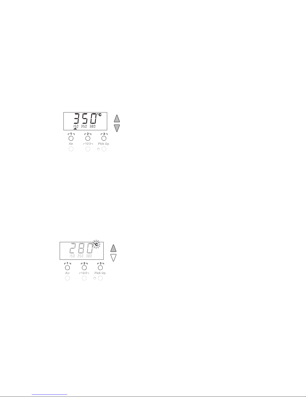
After the device has been switched ON, the microprocessor carries
out a self-test in which all the segments are briefly displayed. Then
the electronics automatically switches to the basic temperature
setting of 720 °F for all channels and 50% for the "Air" setting. A
green LED (2) above each receptacle lights up when activated
channels are being used:

WR 3M Page 7 of 21
ENFRITESPTNLSVDKFIGRTRCZPLHUSKSLEELVLT
−LED lit green constantly indicates that the connected tool is being
heated up.
−LED flashing green indicates that the Set temperature of the tool
has been reached.
Active channels are indicated in the display with a triangle “S”(22)
and a lightning symbol "a“ (21).
6Operating Guidelines
6.1 Selecting a channel, switching ON or OFF
1. Depress one of the Radio Buttons ┌ 1 ┐, ┌ 2 ┐ or ┌ 3 ┐ to select
one of the three channels until the desired channel is displayed.
- Or -
Depress the center ┌ 1·2·3 ┐ Radio Button until the desired
channel is displayed.
The display shows the Set temperature of the selected channel
and - in smaller script - the fixed/pre-set temperatures.
The current tool temperature then appears in the display. The
status with the corresponding Set temperature is also displayed in
the lower area.
The selected channel is indicated by a triangle (22) in the display
and by a red-illuminated LED (1) on the device connection port.
2. To turn the selected channel OFF or ON, depress the UP and
DOWN Scroll Keys simultaneously until three dashes "- - -"
appear in the display. Immediately release Scroll Keys. If "- 1 -"
appears in the screen, press the ┌ 3 ┐ Radio Button to exit the
menu and repeat step #2.
3. If the channel is deactivated, "OFF“ appears in the display. If the
channel is activated, the current Read temperature appears in the
display.
Stored data is not lost when a channel is switched “OFF”.
Note The display switches automatically when:
•a Tool is connected
•when the finger switch is depressed
•when a Tool is removed from the Switching Stand
6.2 Setting the Temperature
Setting the Temperature Individually
1. Select the desired channel by depressing one of the Radio
Buttons ┌ 1 ┐, ┌ 2 ┐ or ┌ 3 ┐.
Or, depress the center Radio Button ┌ 1·2·3 ┐ until the desired
channel is displayed.
The display shows the Read temperature values of the selected
channel.

Page 8 of 21 WR 3M
2. Depress the UP or DOWN Scroll Key. The display switches to the
set value. The temperature symbol (18) flashes.
3. Depress the UP or DOWN Scroll Key to set the desired
temperature:
-Tapping the Scroll Keys changes the Set temperature by one
degree.
-Holding down the Scroll Keys changes the Set temperature
rapidly.
The Set value of the selected channel appears in the display for
approximately 2 seconds after the Scroll Keys are released.
Setting the Pre-set Temperature on Radio Buttons ┌ 1 ┐,┌ 2 ┐ or ┌ 3
┐
The temperature can be set for each channel separately by selecting
three fixed/pre-set Radio Buttons.
1. Select a channel.
Three fixed/pre-set temperatures are shown in the display for
approximately 2 seconds. The temperature can now be Set as
long as the temperature symbol is flashing.
2. Adjust the temperature in the large display with the UP or DOWN
Scroll Keys.
3. Depress the desired Radio Button ┌ 1 ┐, ┌ 2 ┐ or ┌ 3 ┐ for 3
seconds. The temperature display for the corresponding
temperature value flashes during this period. The Set value is
stored after 3 seconds.
4. Release the Radio Button.
Temperature Setting using the Radio Buttons ┌ 1 ┐, ┌ 2 ┐ or ┌ 3 ┐
Factory default settings:
┌ 1 ┐ = 300 °F ( 150 °C ),
┌ 2 ┐ = 660 °F ( 350 °C ),
┌ 3 ┐ = 720 °F ( 380 °C )
1. Select a channel.
Three fixed/pre-set temperatures are shown in the display for
approximately 2 seconds. The temperature can now be Set as
long as the temperature symbol is flashing.
2. The desired fixed/pre-set temperature can now be selected with
Radio Buttons ┌ 1 ┐, ┌ 2 ┐ or ┌ 3 ┐
3. The Set value is adopted. The Read temperature of the selected
channel is displayed after 3 seconds.
6.3 Setting the Air Flow
The Air Flow can, starting from a maximum flow value of 15 l/s (HAP
200) or 10 l/s (HAP 1), be adjusted between 10% to 100%.
1. Depress the AIR button.

WR 3M Page 9 of 21
ENFRITESPTNLSVDKFIGRTRCZPLHUSKSLEELVLT
2 s ➾ Menu 1
4 s ➾ Menu 2
1x ➾ ON/OFF
2. The current air flow in percentage is shown in the display for
approximately 2 seconds.
3. Set the desired flow by Depressing the UP or DOWN Scroll Key.
6.4 Switching the Vacuum Pick-up Pump ON/OFF
ZDepress the Pick-Up Radio Button.
The pump is switched on or off, depending on the initial state. In
switched-on mode, the LED (8) next to the Pick-Up Radio Button
lights up green.
Note The vacuum pump is not designed for continuous operation. (60
Seconds On, 30 Seconds Off). To protect itself, the pump
switches off automatically after 5 minutes of continuous operation.
6.5 Soldering and Desoldering
ZPerform the Soldering / Desoldering work in accordance with the
operating instructions of your connected soldering tool.
7Special Functions
The special functions are divided into 2 menu levels:
−Menu 1 with setting options for Standby temperature, temperature
deactivation (Setback), automatic switch-off time (AUTO-OFF),
temperature Offset, Window function, Degrees °F / °C conversion,
switch-on time (On Time) for hot-air pencil, vacuum OFF delay
(VAC OFF), vacuum ON delay (VAC ON) and Lock function.
−Menu 2 with setting options for Station Desoldering vacuum level,
ID code, Factory Control Check (FCC), and Pick-Up vacuum level
(%).
Selecting Menu 1 Special Functions
Special functions Navigation
STANDBY
SETBACK
AUTO OFF
OFFSET
WINDOW
°F / °C
ON TIME
VAC OFF
VAC ON
↑ ┌ 1 ┐
↓ ┌ 2 ┐
EXIT ┌ 3 ┐

Page 10 of 21 WR 3M
1. Select the desired channel ┌ 1 ┐, ┌ 2 ┐ or ┌ 3 ┐ for entering the
special functions.
2. Depress and hold down the UP and DOWN Scroll Keys
simultaneously.
"– 1 –“ appears in the display after 2 seconds.
3. Release the Scroll Keys.
Menu 1 is activated and the special functions can now be
selected.
-Select menu items with Radio Buttons ┌ 1 ┐(back), or
┌ 2 ┐ (forward).
-Exit the menu with Radio button ┌ 3 ┐ (EXIT).
Setting the Standby Temperature
When the Setback time has elapsed, the “Set” temperature
is decreased automatically to the Standby value. The “Read”
temperature is displayed (flashing) and "STANDBY" appears in the
display. The Standby temperature can be set in the range ( 200 -
600°F / 100 -300°C ).
1. Select the menu item STANDBY in Menu 1.
2. Set the value for the Standby Temperature with the UP or DOWN
Scroll Key.
3. Proceed to the next menu item with the Radio Button ┌ 1 ┐ (back)
or ┌ 2 ┐ (forward) or exit the menu with Radio button ┌ 3 ┐ (EXIT).
Setback Time
When the soldering tool is not in use, the temperature is reduced to
the Standby temperature after the Setback Time has elapsed. The
Setback is indicated by a flashing actual value, (see note) and
"STANDBY“ appears in the display. Depressing the UP or DOWN
scroll key terminates this Setback Time. Depending on the tool, the
finger switch or the switching holder resets the Setback Time.
Note: When using the HAP 1 or HAP 200, the Actual Temperature
will not be displayed for these tools.
The following Setback settings are possible:
−"0 min“: Setback OFF (factory setting)
−"ON“: Setback ON (the system is controlled down to the Standby
temperature when the soldering tool is placed in the switching
holder).
−"1-99 min“: Setback ON (each channel individually selectable).
1. Select the menu item SETBACK in Menu 1.
2. Set the Setback value with the UP or DOWN Scroll Key.
3. Proceed to the next menu item with the Radio Button ┌ 1 ┐ (back)
or ┌ 2 ┐ (forward) or exit the menu with Radio button ┌ 3 ┐
(EXIT).
Note Assigning a low pre-set temperature to a Radio Button offers the
possibility of manual temperature reduction (Setback) when the
soldering / desoldering tool is not in use.

WR 3M Page 11 of 21
ENFRITESPTNLSVDKFIGRTRCZPLHUSKSLEELVLT
Setting the Automatic “Switch-Off” Time (AUTO-OFF)
When the soldering tool is not in use, heating of the soldering tool is
switched off after the AUTO-OFF time has elapsed. The Auto-Off can
be set from 0-999 minutes for each channel independently. With a
setting of "0 min", the Auto Off function is disabled. Auto Off is carried
out independently of the Setback function. The “Read” temperature is
displayed (flashing) and may be monitored as a decreasing heat
indicator; "OFF" appears in the display in small script above the
selected channel. Below 122°F ( 50°C ), a flashing dash appears in
the center of the display.
The following AUTO-OFF time settings are possible:
−"0 min“: AUTO-OFF function is switched off
−"1-999 min“: AUTO-OFF time, each channel individually selectable
1. Select the menu item OFF in Menu 1.
2. Set the AUTO-OFF Set time with the UP or DOWN Scroll Key.
3. Proceed to the next menu item with the Radio Button ┌ 1 ┐ (back)
or ┌ 2 ┐ (forward) or exit the menu with Radio button ┌ 3 ┐ (EXIT).
Tool Operation with different settings of the SETBACK and AUTO
OFF functions
Settings
SETBACK
Time [1-99
min]
OFF Time [1-
999 min]
Tool Operation without Switching Holder
0
ON 0Soldering tool remains at the Set soldering temperature.
0
ON Time Soldering tool is switched off when not in use1) after the OFF time
has elapsed.
Time 0 Soldering tool is controlled down when not in use1) to the STANDBY
temperature2) after the SETBACK time has elapsed.
Time Time
Soldering tool is controlled down when not in use1) to the STANDBY
temperature2) after the SETBACK time has elapsed and is switched
off after the OFF time has elapsed.
Tool Operation with Switching Holder
0 0 Soldering is switched off in the holder3).
ON 0 Soldering tool is controlled to the STANDBY temperature2) when in
the holder3) .
0Time
Soldering tool is switched off after the OFF time has elapsed when
in the holder3).
ON Time Soldering tool is controlled to the STANDBY temperature2) and is
switched off after the OFF time has elapsed when in the holder3).
Time 0 Soldering tool is controlled to the STANDBY temperature2) after the
SETBACK time has elapsed when in the holder3).
Time Time
Soldering tool is controlled to the STANDBY temperature2) after the
SETBACK time has elapsed and is switched off after the OFF time
has elapsed when in the holder3).

Page 12 of 21 WR 3M
1) Not in use = UP/DOWN Scroll Keys not depressed and no temperature drop > 41 °F.
2) STANDBY temperature must be below the Set temperature, otherwise the SETBACK function is
inactive.
3) When a switching holder is connected, the soldering tool always remains at the Set temperature
outside the holder.
The holder function is activated when the soldering tool is placed in the holder for the first time.
Note Reset of STANDBY and AUTO OFF modes:
−without switching holder, by depressing the UP or DOWN Scroll Keys.
−with switching holder, by removing the soldering tool from the holder.
Setting the Temperature Offset
The Read soldering-tip temperature can be adjusted by entering a
temperature offset ± 72 °F ( ± 40 °C ).
1. Select the menu item OFFSET in Menu 1.
2. Set the OFFSET temperature value with the UP or DOWN Scroll
Key.
3. Proceed to the next menu item with the Radio Button ┌ 1 ┐ (back)
or ┌ 2 ┐ (forward) or exit the menu with Radio button ┌ 3 ┐ (EXIT).
Setting the Window Function
It is possible, starting from a Set, Locked temperature, to set a
temperature range of ± 180 °F ( ± 99 °C ) with the WINDOW function.
The temperature range (Window) must be Set prior to Locking the
station.
Note To be able to use the WINDOW function, make sure the Rework Station
is in the Locked mode (see "Switching the lock function on/off“ Page
10).
1. Select the menu item WINDOW in Menu 1.
2. Set the WINDOW temperature value with the UP or DOWN Scroll
Key.
3. Proceed to the next menu item with the Radio Button ┌ 1 ┐ (back)
or ┌ 2 ┐ (forward) or exit the menu with Radio button ┌ 3 ┐ (EXIT).
Switching the Temperature Display
Switching the temperature display from °F to °C or vice versa.
1. Select the temperature display °F / °C in Menu 1.
2. Set the temperature display with the UP or DOWN Scroll Key.
4. Proceed to the next menu item with the Radio Button ┌ 1 ┐ (back)
or ┌ 2 ┐ (forward) or exit the menu with Radio button ┌ 3 ┐
(EXIT).
Limiting the Time (HAP ON) time for Hot-Air Pencil
With the HAP-On time for the Hot Air Pencil, hot-air flow can be
limited in increments of 1, from 0 to 60 seconds. The set time is then
identical for all 3 channels. Factory setting is 0 seconds ("OFF“), i.e.

WR 3M Page 13 of 21
ENFRITESPTNLSVDKFIGRTRCZPLHUSKSLEELVLT
the airflow is activated as long as the push-button on the hot-air
pencil is depressed.
1. Select the menu item HAP-On in Menu 1.
2. Set the time value with the UP or DOWN Scroll Key.
3. Proceed to the next menu item with the Radio Button ┌ 1 ┐ (back)
or ┌ 2 ┐ (forward) or exit the menu with Radio button ┌ 3 ┐ (EXIT).
Setting the Vacuum OFF delay (VAC OFF)
To prevent the Desoldering tip from becoming clogged, it is possible
to set a vacuum OFF delay of 0 to 5 seconds (factory setting 2
seconds).
1. Select the menu item VAC OFF in Menu 1.
2. Set the time value (VAC OFF) with the UP or DOWN Scroll Key.
3. Proceed to the next menu item with the Radio Button ┌ 1 ┐ (back)
or ┌ 2 ┐ (forward) or exit the menu with Radio button ┌ 3 ┐ (EXIT).
Setting the Vacuum ON delay (VAC ON)
In order to prevent the pump from starting before the solder has
melted. Or to create a defined soldering-joint preheat time, it is
possible to set an ON delay of 0 to 9 seconds (factory setting 0
seconds: Off).
1. Select the menu item VAC ON in Menu 1.
2. Set the time value (VAC ON) with the UP or DOWN Scroll Key.
3. Proceed to the next menu item with the Radio Button ┌ 1 ┐ (back)
or ┌ 2 ┐ (forward) or exit the menu with Radio button ┌ 3 ┐ (EXIT).
Switching the Lock Function (On/Off)
When the Lock has been switched on, only the Radio Buttons ┌ 1 ┐,
┌ 2 ┐ and ┌ 3 ┐ on the Rework Station can still be operated. All other
settings are disabled until the Rework Station is unlocked again.
To LOCK the Rework Station:
1. Select the menu item LOCK in Menu 1.
"OFF“ appears in the display. The padlock symbol flashes.
Note Depressing the Radio buttons ┌ 1 ┐ or ┌ 2 ┐ while "OFF“ is displayed
results in the menu item being exited without a stored lock code.
2. Set a 1, 2, or 3-digit Lock code with the UP or DOWN Scroll Key.
Note: The code must be retained to Unlock the station.
3. Depress Radio Button ┌ 3 ┐ for 5 seconds.
The code is stored. The padlock symbol is displayed. The Station
is now locked.
4. Proceed to the next menu item with the Radio Button ┌ 1 ┐ (back)
or ┌ 2 ┐ (forward) or exit the menu with Radio button ┌ 3 ┐ (EXIT).
To unlock the Rework Station:
1. Select the menu item LOCK in Menu 1.
"ON“ appears in the display. The padlock symbol is displayed.

Page 14 of 21 WR 3M
2. Enter the 1, 2, or 3-digit LOCK code with the UP or DOWN Scroll
Key.
3. Depress Radio Button ┌ 3 ┐. The Station is now unlocked.
Resetting the Special Functions to Factory Default Settings
1. Select the Special Functions Menu 1.
2. Depress and hold down Radio Button ┌ 3 ┐.
3. Then Depress the UP and DOWN Scroll Keys simultaneously.
"FSE", Factory Setting Enabled appears in the display.
The Rework Station is now reset to the factory default settings.
4. Exit the menu with Radio Button ┌ 3 ┐ (EXIT).
7.1 Selecting Menu 2 Special Functions
Special Functions Navigation
LEVEL
ID
FCC
PICK-UP
↑ ┌ 1 ┐
↓ ┌ 2 ┐
EXIT ┌ 3 ┐
1. Select the desired channel ┌ 1 ┐, ┌ 2 ┐ or ┌ 3 ┐ for entering the
special functions.
2. Depress and hold down the UP and DOWN Scroll Keys
simultaneously.
"– 2 –" appears in the display after 4 seconds.
3. Release the Scroll Keys.
Selection of the special functions of Menu 2 is activated.
The settings can now be made.
−Select menu items with Radio Buttons ┌ 1 ┐ and ┌ 2 ┐.
−Exit the menu with Radio Button ┌ 3 ┐ (EXIT).
Defining the Maintenance Level of the Vacuum System ( VAC and
bar )
−The value is shown in mbar at which the electric vacuum gauge
issues a vacuum level warning signal. The LED (3) of the vacuum
pump switches from green to red. The set value is dependent on
the desoldering tiplets used.
−Factory setting: -600 mbar
Settable: -400 mbar to -800 mbar
1. Select the menu item LEVEL in Menu 2.
2. Set the vacuum value LEVEL with the UP or DOWN Scroll Key.
3. Proceed to the next menu item with the Radio Button ┌ 1 ┐ (back)
or ┌ 2 ┐ (forward) or exit the menu with Radio button ┌ 3 ┐ (EXIT).
Setting the Station Identification ( REMOTE ID code )
When the optional USB port is used, several WR 3M Rework
Stations can be activated and remote-controlled. Each Station

WR 3M Page 15 of 21
ENFRITESPTNLSVDKFIGRTRCZPLHUSKSLEELVLT
requires a Station Identification (ID code) so that it can clearly be
identified.
1. Select the menu item REMOTE ID in Menu 2.
2. Enter an ID with the UP or DOWN Scroll Keys
(possible values 0 – 999).
3. Proceed to the next menu item with the Radio Button ┌ 1 ┐ (back)
or ┌ 2 ┐ (forward) or exit the menu with Radio button ┌ 3 ┐ (EXIT).
Note Depress Radio Button ┌ 3 ┐ to exit the menu item without saving any
changes (EXIT).
Factory Control Check ( FCC )
This function checks temperature accuracy of the Rework Station
and allows modifications if necessary. To perform the “FCC” function,
the soldering tip temperature must be measured using an external
temperature measuring instrument, (WA2000) and appropriate type
“K” temperature measuring tip. ( See Accessories List on page 18 )
Control Check at 212 °F / 100 °C
1. Connect the type “K” thermocouple, into the external temperature
measuring instrument, (WA2000).
2. Select the menu item FCC in Menu 2.
3. Depress the DOWN Scroll Key. Control point 212 °F / 100 °C is
selected.
The soldering tip is now heated to 212 °F / 100 °C.
The Heater Control Indicator flashes (a) (21) as soon as the
temperature is constant.
4. Compare the temperatures indicated by the meter with the
indications in the display.
5. Use the UP or DOWN Scroll Key to set the difference between the
value indicated on the external meter and the value indicated on
the Rework Station, (shown in small script in lower part of the
display). Maximum temperature adjustment: ± 72 °F (± 40 °C).
Example:
Display 212 °F, external meter 210 °F: setting S 2
Display 212 °F, external meter 214 °F: setting T 2
Note Depress Radio Button ┌ 3 ┐ to exit the menu item without saving
changes (EXIT).
6. Depress Radio Button ┌ 2 ┐ (Set) to confirm the value.
The temperature deviation is now reset to 0. Factory Control
Check at 212 °F / 100 °C is now complete.
7. Exit Menu 2 by depressing Radio Button ┌ 3 ┐ twice.
Control Check at 842 °F / 450 °C
1. Connect the type “K” thermocouple, into the external temperature
measuring instrument, (WA2000).

Page 16 of 21 WR 3M
2. Select the menu item FCC in Menu 2.
3. Depress the UP Scroll Key. Control point 842 °F / 450 °C is
selected.
The soldering tip is now heated to 842 °F / 450 °C.
The Heater Control Indicator flashes (a) (21) as soon as the
temperature is constant.
4. Compare the temperatures indicated by the meter with the
indications in the display.
5. Use the UP or DOWN Scroll Key to set the difference between the
value indicated on the external meter and the value indicated on
the Rework Station, (shown in small script in lower part of the
display). Maximum temperature adjustment: ± 72 °F (± 40 °C).
Example:
Display 842 °F, external meter 840 °F: setting S 2
Display 842 °F, external meter 844 °F: setting T 2
Note Depress Radio Button ┌ 3 ┐ to exit the menu item without saving
changes (EXIT).
6. Depress Radio Button ┌ 2 ┐ (Set) to confirm the value.
The temperature deviation is now reset to 0. Factory Control
Check at 842 °F / 450 °C is now complete.
7. Exit Menu 2 by depressing Radio Button ┌ 3 ┐ twice.
Setting the Pick-Up Vacuum Level
This function can be used to set the vacuum level of the vacuum
pick-up pump operation:
−Factory setting: 85 %
−Variable: 50 % – 100 %
1. Select the menu item LEVEL in Menu 2. “PIC UP” appears in the
display
2. Set the Pick-up level with the UP or DOWN scroll keys.
3. Proceed to the next menu item with the button ┌ 1 ┐ (back) or
┌ 2 ┐ (forward) or exit the menu with Radio button ┌ 3 ┐ (EXIT).
Note: The “ FCC “ Offset values can be reset to the Factory Setting
in the Special Functions Menu 2 without affecting other settings of
the Rework Station. ( See “Resetting the Special Functions to
Factory Default Settings” on page 14 of 21. )
* For Details concerning “FCC“ Default Settings, please contact
Weller Technical Services.
8Maintaining and Servicing the WR 3M
8.1 Changing the Filter
Regularly check the main filters for “VACUUM” and “AIR” and replace
if necessary.

WR 3M Page 17 of 21
ENFRITESPTNLSVDKFIGRTRCZPLHUSKSLEELVLT
WARNING! Vacuum pump will be destroyed if operated without
the filter.
ZCheck to ensure the filters are in place before operating unit.
Replacing the filter
1. Turn the cover cap for "Vac“ (14) or "Air“ (15) 45°
counterclockwise and remove.
2. Pull out the contaminated filter and dispose of properly.
3. Insert an original WELLER filter cartridge.
Make sure that the cover seal is correctly seated.
4. Insert pressure spring.
5. Align the cover cap with slight pressure and turn 45° clockwise.
9Fault Indications and Correction
Indication/symptom Possible cause Corrective Action
Display: "- - -" −Tool has not been detected
−Tool defective
−Check connection of tool to
device
−Check connected tool
HAP 200 does not function HAP 200 not connected to
channel 1
Connect HAP 200 to channel 1
Display: "tip" Soldering tip of WMRP
Microtool or WMRT Micro-
Tweezer not correctly inserted
or defective
−Insert soldering tip or Tweezer
Cartridge again
−Replace defective soldering tip
or Tweezer Cartridge
Pick-up does not function
correctly
−Vacuum is not fully built up
−Hose defective or kinked
−Check vacuum at pick-up
connection
−Replace/straighten hose
No air at HAP Air hose not or incorrectly
connected
Connect air hose to AIR port
No vacuum on Desoldering
tool
−Vacuum hose not or
incorrectly connected
−Desoldering Tiplet clogged
−Desoldering Filter clogged
−Connect vacuum hose to Vac
port
−Clean Desoldering Tiplet with
cleaning tool
−Replace Desoldering Tool
Filter
Status indication of Vac
LED’s incorrect
Vacuum level not correctly set Set vacuum level in special menu
2
No display function (display
off)
No power supply voltage −Turn on power switch
−Check power supply voltage
−Check device fuse
VAC LED red Vacuum system clogged −Clean suction nozzle or
replace Desoldering Tiplet
−Check filter (13); replace if
clogged

Page 18 of 21 WR 3M
−Clean desoldering tool –
replace filter
−Check vacuum hose
10 Accessories
0052918399 WMRP Micro Soldering-tip set, 40 W; WDH 30T
Stand, RT3 tip.
0051514599 WMRH Micro Soldering Tool Switching Holder
0051317399 WMRT Micro Desoldering-tweezer set, 80 W
005xxxxxxxRTWX Tip set ???
0051514699 WMRTH Micro Desoldering-tweezer Switching
Holder
0052918199 WP 80 Soldering-tip set, 80 W; WDH 10 Stand
0052916199 WSP 80 Soldering-tip set, 80 W; WDH 10 Stand
0053315999 WMP Soldering-tip set, 65 W; WDH 20T Stand
0052917999 WMP Soldering-tip set, 65 W; WDH 20 Stand
0053313399 WTA 50 Desoldering-tweezer set, 50 W; AK 51
Stand
0053313599 WSP 150 Soldering-tip set, 150 W; WDH 30 Stand
0053312199 MPR 80 Soldering pencil set, 80 W; KH 25P Stand
0052704099 WSB 80 Soldering bath, 80 W
0052704299 WSB 150 Soldering bath, 150 W
0052702899 WHP 80 Preheating plate, 80 W
005xxxxxxxWHP 150 Preheating Plate, 150W
0051318299 DXV 80 Inline Desoldering-tip set, 80 W; WDH 40
Stand
0051318199 DXV 80 Inline Desoldering-tip set, 80 W; AKV 80
Stand
0053313899 DSX 80 Desoldering Iron and Service Kit, 80 W;
WDH 30 Stand
0051319099 DSX 80 Desoldering Iron, 80 W; DX 113HM Nozzle
0051315000 DX 113HM Nozzle with Improved Thermal Transfer
0051350099 Service Kit, DSX / DXV
0053311499 HAP 1 Hot-air pencil set, 100 W; WDH 30 Stand
0051515499 Support for WRK Chip Removal Kit
0051515599 WRK Chip Removal Kit
0052918499 WVP Vacuum Pipette
0052711699 HAP 200 Hot-air pencil, 200 W
0052711799 HAP 200 Hot-air set, 200 W; WDH 30 Stand
0051515299 WDH 30 Holder for HAP 200 / DSX 80; HAP1 /
WSP150
0058761728 Adapter for HAP200 Hot Air Pencil
0051515399 WDH 40 Holder for DXV 80
0051516199 WDH 10T Switching holder WSP 80/WP 80
0051516299 WDH 20T Switching holder for WMP
0058761730 Desoldering set 33x33/24x24 with pick-up
0058761731 Desoldering set 27x27/20x20 with pick-up

WR 3M Page 19 of 21
ENFRITESPTNLSVDKFIGRTRCZPLHUSKSLEELVLT
0058761732 Desoldering set 18/15.5/12.5/10 with pick-up
0051512499 WDC Weller Dry Tip Cleaner
0051512599 WDC 2 Dry Tip Cleaner for WDH Stands
0051303199 Lead Free Tip Tinner / Activator
0051350099 Cleaning Tool for Desoldering Pencils
0051312499 Spare Filters for DSX 80 Desoldering Pencil
0058741815 Spare Filter Cartridges for DXV 80 Desoldering
Pencil 5/Pack
0052241999 Replacement Sponge, 5/Pack
0051515699 WDH 50 Safety Rest
0051503399 KH 25P Safety Rest
WA2000 Soldering Tool Analyzer
K181 Thermocoupled Tip for WSP80
K191 Thermocoupled Tip for WMP
K1111 Thermocoupled Tip for WP80
K1101 Thermocoupled Tip for WMRP
WPB1 Tip Polishing Bar
11 Disposal
Dispose of replaced equipment parts, filters or old devices in
accordance with the rules and regulations applicable in your country.
12 Warranty
Cooper Hand Tools warrants to the original purchaser and any
subsequent owner (“Buyer”) that Weller soldering and desoldering
products will be free from defects in material and workmanship for a
period of one year from date of purchase, provided that no warranty
is made with respect to products which have been altered, subjected
to abuse or improperly used, installed or repaired. Use of non-
Cooper Hand Tools components will void this warranty if a non-
Cooper Hand Tools component is defective (or is the source of the
defect). Cooper Hand Tools will repair or replace products found to
be defective not caused by a part, component or accessory
manufactured by another company, during the warranty period.
Contact Cooper Hand Tools with dated proof of purchase and return
to Cooper Hand Tools, 1000 Lufkin Road, Apex, NC 27539. All costs
of transportation and reinstallation shall be borne by Buyers.
IN NO EVENT SHALL COOPER HAND TOOLS BE LIABLE FOR
INCIDENTAL OR CONSEQUENTIAL DAMAGES. COOPER HAND
TOOLS LIABILITY FOR ANY CLAIMS ARISING OUT OF THIS
WARRANTY SHALL NOT EXCEED THE PURCHASE PRICE OF
THE PRODUCT.

Page 20 of 21 WR 3M
THE PERIOD OF ALL IMPLIED WARRANTIES APPLICABLE TO
THIS PRODUCT INCLUDING ANY IMPLIED WARRANTY OF
MERCHANTABILITY OR FITNESS, OR FITNESS FOR A
PARTICULAR PURPOSE IS LIMITED TO 12 MONTHS FROM THE
DATE OF PURCHASE BY THE USER.
Some states do not allow the exclusion or limitation of incidental or
consequential damages, so the above limitation or exclusion may not
apply to you. Some states do not allow limitation on how long an
implied warranty lasts, so the above limitation may not apply to you.
This warranty gives you specific legal rights, and you may also have
other rights, which vary, from state to state.
www.Cooperhandtools.com
Weller is a registered Trademark and registered Design of Cooper
Industries, Inc.
U.S Mailing Address:
Cooper Hand Tools
P.O. Box 728
Apex, NC 27502-0728
U.S Shipping Address:
1000 Lufkin Road
Table of contents