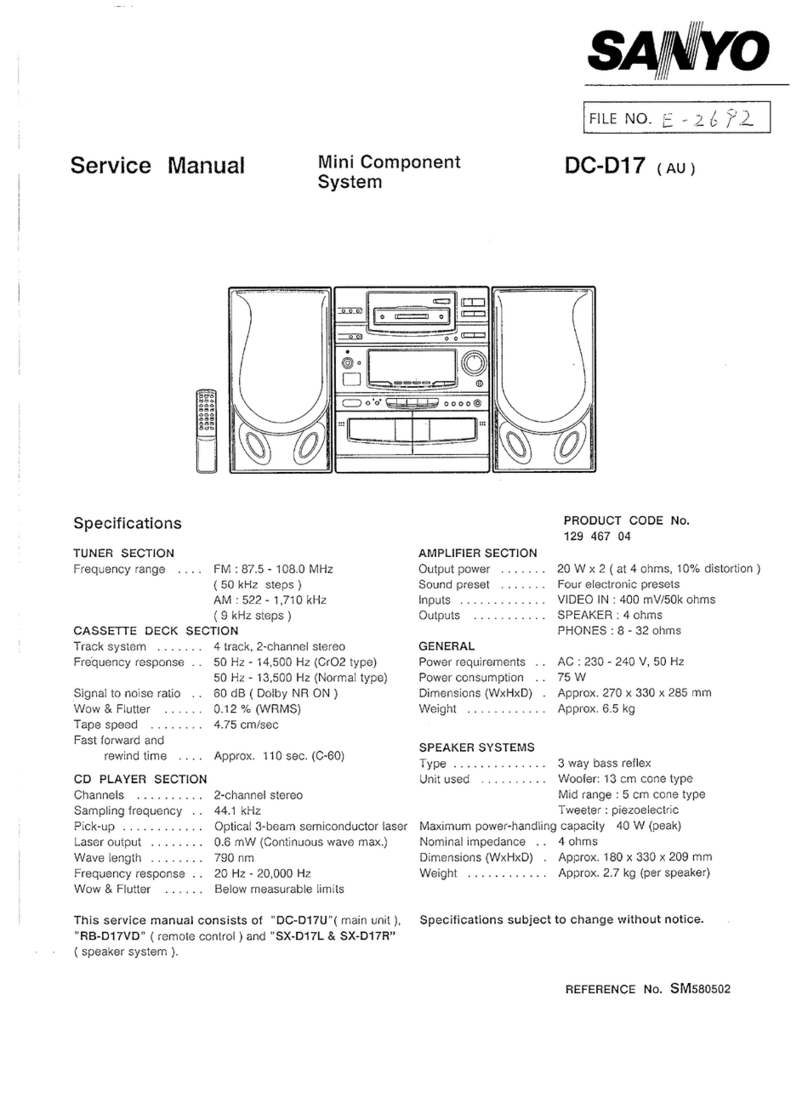
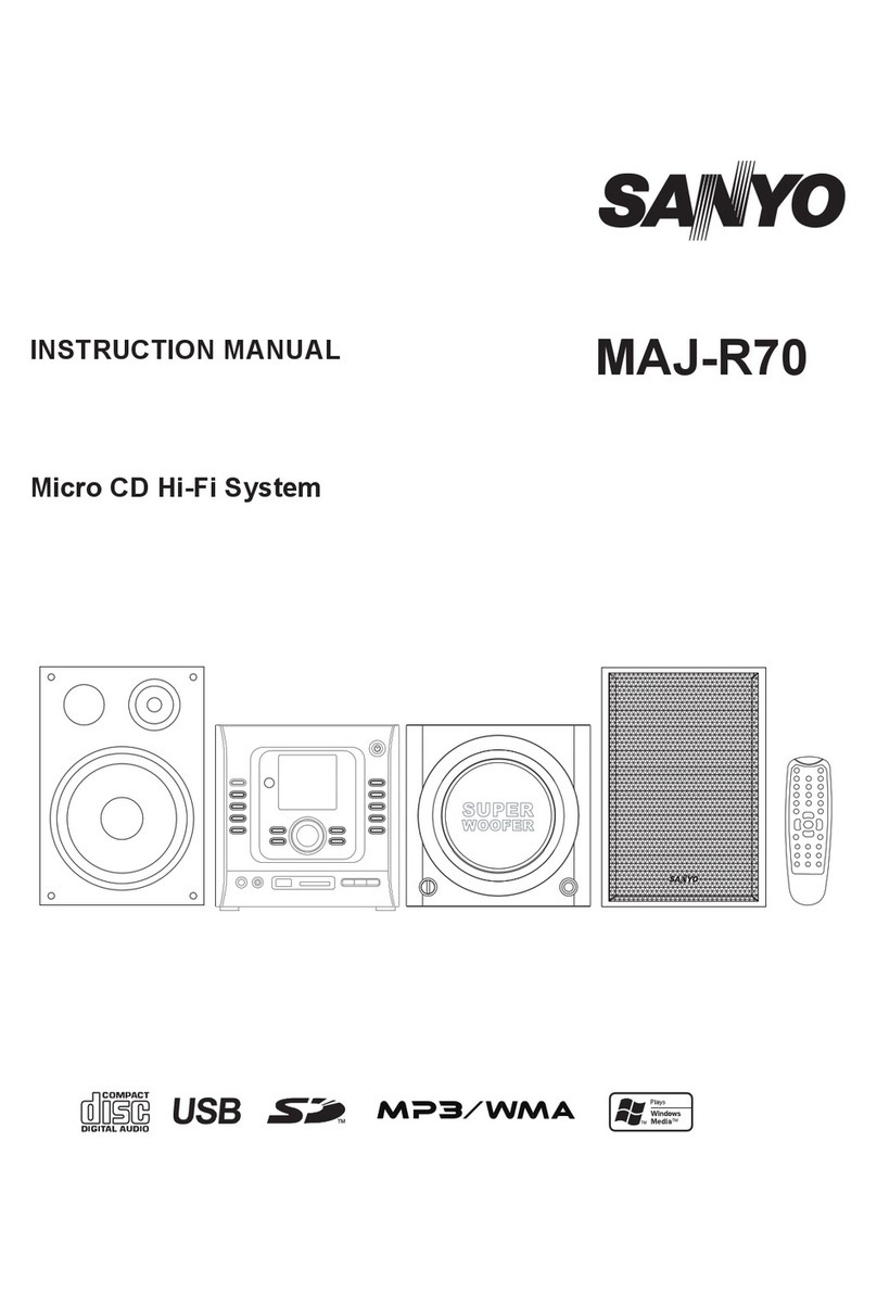
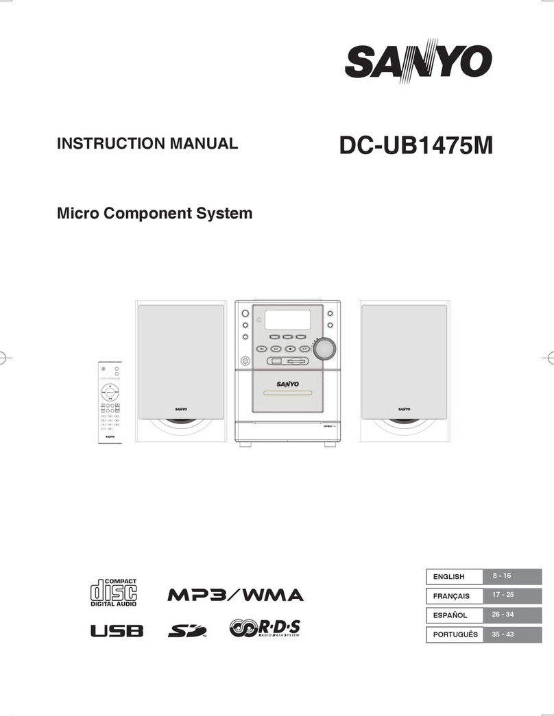
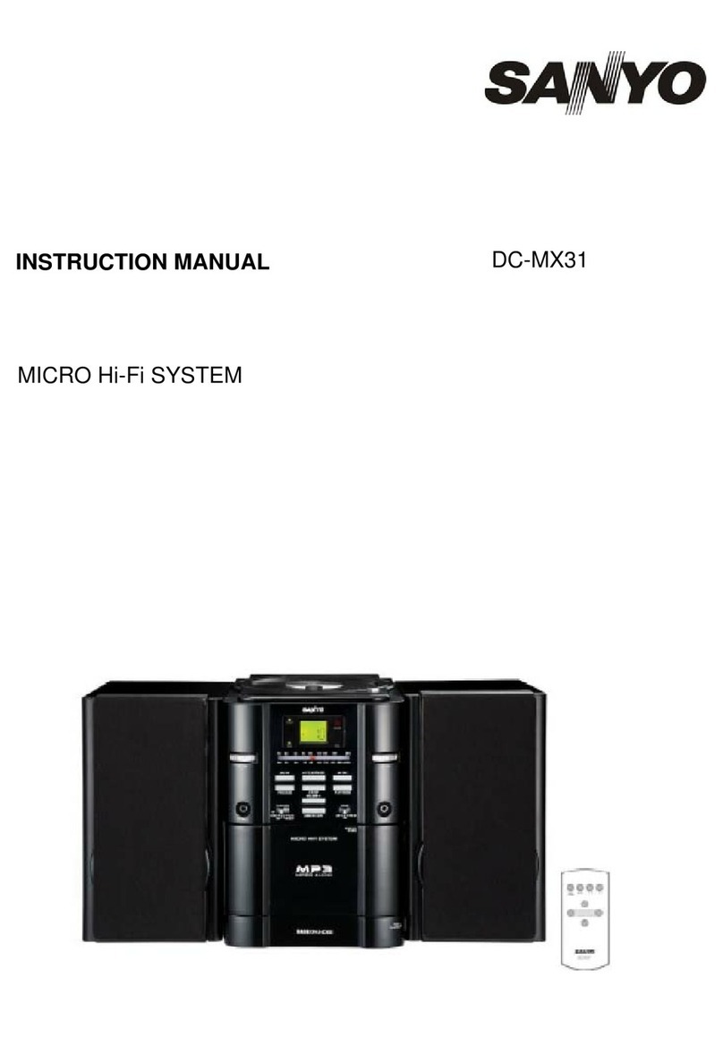
Sanyo GXT 4615K User manual

ANYO
STEREO
MUSIC
SYSTEM
GXT
4615K
SERVICE
MANUAL
A
PRODUCT
OF
SANYO
ELECTRIC
CO.,
LTD.

SPECIFICATIONS
ee
+
GENERAL
Transistors
2SC668
E
x
1
2SC668
D
x
1
2SC930
D
x
1
2SC
1648
x
2
28C537
E
x2
2SC1647
x
1
Diodes
BZO090
x
1
181588
x
1
18188
x
1
18188
x
1
181588
x
1
18188
x
2
18188
x
1
1001
x
3
SLP-24
x
1
IC's
LA1201
x
1
BA1310
x
1
103150
x
2
LA4032P
x
2
Power
source
Dimensions
Power
consumption
Weight
TUNER
SECTION
Frequency
ranges
-
intermediate
frequency
Sensitivity
S/N
=
20 dB
S/N
=
30
dB
Signal-to-noise
ratio
FM
MPX
separation
$
FM
RF
Amplifier
-
FM
Converter
AM
Converter
Pre.
Amplifier
Bias
Oscillator
MPX
Amplifier
Voltage
Regulator
Transistor
Protector
FM
A.G.C.
AM
A.G.C.
FM
Limiter
FM
Discriminator
Rectifier
Rectifier
Dial
Pointer
(LED)
FM
&
AM
IF
Amplifier
MPX
Switching
&
Amplifier
Cassette
Pre.
Amptifier
Main
Amplifier
120/200/220/240V
AC
50/60
Hz
©
505(W)
x
365(D)
x
210(H)mm
23W
:
Approx.
8.5
kg
(19
ibs.)
AM
530
—
1605
KHz
FM
88
—
108
MHz
AM
455
KHz
FM
10.7
MHz
AM
280
uV/m
FM
10
uV
AM
44
dB
FM
50
dB
30
dB
AMP
SECTION
|
Output
power
Frequency
response
Power
bandwidth
Signal-to-noise
ratio
Output
terminal
Speaker
impedance
Tape
playback
output
input
terminal
Tape
recording
signal
fevel
PLAYER
SECTION
Turntable
speed
Pick-up
system
Wow
&
flutter
Turntable
diameter
CASSETTE
SECTION
Recording
system
Erasing
system
Tape
speed
Rewinding
&
F-Forward
Wow
&
fiutter
SPEAKER
SECTION
Speaker
size
Input
power
Dimensions
Weight
2.5
Watt
(10%
THD)
30
—
25,000
Hz
45
—
20,000
Hz
60
dB
8
ohm
300
mV
400K
ohm
imp.
200
mV
50K
ohm
imp.
33-1/3,
45
&
78
rpm
Ceramic
Stereo
Cartridge
0.2%
10”
AC
Bias
AC
Erasing
1-7/8
inch/sec.
120
sec.
(C-60)
(
0.2%
ae”
4-3/4"
5
Watt
9-1/8"
(W)
x
6-1/8"
(D)
x
14-3/8"'(H)
230(W)
x
155(D)
x
365(H}mm
Approx.
1.9
kg
(4-3/16
Ibs.)

v
AM
IF
AND
RF.ALIGNMENT
,
Signal
Frequency
and
Dial
Setting
Components
to
be
ae
BS
KHz
30%
|
Lowerend
[OSC
col
6
600
KH
30%
«|
BOO
KHz
|
Ant
col
LS
Repeat
step
4
and
5.
|
BIAS
CURRENT
ADJUSTMENT
Adjust
SVR-1
to
develop
0.65V
across
Tp-1
and
Tp-2.
FM
IF
ALIGNMENT
Alignment
Test
Equipment
1
10.7
MHz
Connect
sweep
generator
to
CT-2
Tune
T1, T2,
T3,
T4
and
T5
for
and
oscilloscope
to
test
point
max.
gain
and
symmetry
of
Tp-4
response
curve
(Fig.
1)
Connect
sweep
generator
to
CT-2
Tune
T6
for
symmetrical
‘’S”
and
oscilloscope
to
test
point
curve
(Fig.
2)
R110
RF
ALIGNMENT
Signal
Input
Frequency
and
Dial
Setting
Components
to
be
Modulation
of
SSG
of
Radio
Adjusted
for
Max.
Output
Thru
dummy
ANT.
87.0
MHz
30%
Fig.
3
110
MHz
30%
90
MHz
30%
|
SOMHz
106
MHz
30%
.
106
MHz
ae
pea
FM
MPX
ADJUSTMENT
r
Test
Instrument
Frequency
|
SVR-101
TP-101
Frequency
Counter
Adjustment
(Input
impedance:
{19,000
Hz
100K
ohm)
+50
Hz}
RECORDING
BIAS
R611
Component
to
be
Adjusted
Test
Instrument
.
V.T.V.M.
SVR
601
(L
channel)
SVR
701
(R
channel)
Bias
Current
Adjustment
(4.5
mV)
Repeat
STEP
3,
4,
5
and
6.
Fig.
1
Symmetrical
Fig.
2
| |
Fig.
3
response
curve
Sy
mmetrical
r
eT
ee
ee
10.7
MHz
marker
.
"6!
gurve
oe
Fite
ee
a,
See
$.6:G
75
ohm
|
0.7
MHz
marker
—AAApenl)
To
Antenna
terminal
>
75
ohrns
150
ohms
Q
To
common
ground
300
ohms

—4—
CABINET
EXPLODED
VIEW

PARTS
LIST
PACKAGE
PARTS
instruction
book
Styrofoam
cushion,
Set
right
R-477
136
7a
R-4170614
R-4170615
Styrofoam
cushion,
Set
left
R-4170097
Styrofoam
cushion,
Speaker
box
R-4072585
Individual
carton
R-4770194
Caution
label
R-4771387
Tag,
Power
_
R-397194
Cover,
Stylus
R-357
269
Cover,
Dust
Ribbon,
Pick
up,
12
x
360
Polyethylene
bag,
100
x
240,
AC
cord
Polyethylene
bag,
Set
Polyethylene
bag,
Oust
cover
Polyethylene
bag,
100
x
240,
Mic
Polyethylene
bag,
160
x
245,
Instruction
book
Polyethylene
bag,
Speaker
box
R-357268
R-357228
R-357175
ACCESSORIES
;
CABINET
APPEARANCE
PARTS
|
Microphone,
400
ohms,
w/Remote
Switch
Microphone,
400
ohms
R-S07137
R-S07138
R-S07037
Cassette
Tape
R-S857b
Plug
Adaptor,
Siemens
type
R-S8575b
Plug
Adaptor,
England
type
R-S870673
Cabinet
assembly
R-1170717
Metal
bracket,
Dust
cover
R-3970762
Base
Screw,
Round
Hd.
Wood,
3.1
x
10
Washer,
Flat,
3.3
x
10
x
1
|
Base
Screw,
Pan
Hd.,
4x12
Washer,
Flat,
4.
x
10x
0.5
Fix
plastic
board
Screw,
Flat
Hd.
Wood,
2
x8
Rear
cover
Screw,
Round
Hd.
Wood,
3.1
x
13
Tap.
Screw,
Pan
Hd.,
3
x
8
Panel
assembly,
with
dial
scale
Dust
cover
assembly
Hinge
A,
Dust
cover
Metai
bracket
Screw,
Pan
Hd.,
3x8
Hinge
B,
Cabinet
Screw,
Round
Hd.
Woad,
3.1
x
13
Panel
assembly,
Cassette
Fix
metal,
Cassette
panel
Front
&
Rear
Tap.
Screw,
Pan
Hd.,
3
x
8
Knob,
Tuning
K
nob,
Turina
Votumne/Punction
Screw,
Nut
&
Washer
Screw,
Pan
Hd.,
4
x
12
Washer,
Lock,
4.5
x
16
x
0.8t
Chassis
—
Cabinet
R-3970762
R-3970597
R-4072583
R-A71292
|
>
R-A71293
-
R-S870669a
R-11707
188
R-11707
16a
R-A71294
R-127911
©
R-3970901
R-3970760L.
NN
Bob
NOBNENNAHANWINNNNNNNNS
SPEAKER
BOX
APPEARANCE
PARTS
R-A71120
—
ese
box
airipl
ete
R-S870715
Speaker
box
R-4071621
Rear
cover
R-327263a
Fix
plastic
board.
R-2670428
Badge
Nut,
SPN-2.6
Screw,
Round
Hd.
Wood,
3.1
x
13
R-S07159
Speaker
Nut,
Hex
Hd.
with
Washer,
3
Cord
assembly
R-$37039-4
—5—
Key
ae
CHASSIS
MECHANICAL
PARTS
|
Chassis
Tap.
Screw,
Pan
Hd.,
3
x
10
Metal
bracket,
Amp.
P.C.B.
left
Metal
bracket,
Amp.
P.C.B8.
right
Tap.
Screw,
Pan
Hd.,
3
x
8
Metal
bracket,
Mic
terminal
Tap.
Screw,
Pan
Hd.,
3x
8
Metal
bracket,
RF
P.C.B.
left
Tap.
Screw,
Pan
Hd.,
3
x
10
Holder,
Power
lamp
Rail,
Pointer
Tap.
Screw,
Pan
Hd.,
3x
6
Back
plate
a
Metal
bracket,
Metal
bracket
left
—
Back
chassis
Tap.
Screw,
Pan
Hd.,
3
x
8
R-1270066
R-1270067
R-1270068
R-1270069
R-1270070
R-447886_
R-1
270071
R-1270072
R-1270073a
R-1270074
Chassis,
Back
R-1270088
Pointer
R-S870668
Shaft
assembly,
Tuning
Nut,
Hex
Hd.,
8
R-147054-2
Shaft,
Pulley
Washer,
Flat,
3.3
x
8
x
0.5t
Pulley
shaft
—
RF
P.C.B.
Puiley
Dial
cord
string,
0.5
x
840mm
Metal
bracket,
Antenna
coil
Tap.
Screw,
Pan
Hd.,
3
x
8
Drum
R-325017
R-127355
R-33226
R-247136
Special
screw,
Drum
R-155026
Coil
spring,
Drum
R-4170321
Metal
piane,
Level
meter
R-377035
Bushing,
AC
cord
R-327033
Mask
sheet,
Level
switch
Heat
sink,
IC;
Tap.
Screw,
Pan
Hd.,
3x
8
Shield
case,
Cassette
‘OSC
Shield
plate,
Cassette
P.C.B.
Tap.
Screw,
Pan
Hd.
with
Washer
“A"
2.6x6
Special
screw,
Shield
plate
Mold
plane,
Cassette
OSC
P.C.B.
Metal
bracket,
Tuning
shaft
Tap.
Screw,
Pan
Hd.,
3
x
10
Spring
Tap.
Screw,
Pan
Hd.,
3
x
8
Washer,
Flat,
3.3
x
10x
It
Metal
bracket,
Cassette
leaf
switch
Lamp
holder,
Stereo
Tap.
Screw,
Pan
Hd.,
3x
6
Metal
bracket,
Mic
terminal
R-277346
R-117739¢
R-277233
R-247244
R-415279
R-1270138
R-157178
R-127779a
R-3970969
R-1270218
ae
eed
oe
ed
met
A
A}
od
ont
awe
hw
|
4
|
A)
oO
AD
=
Description
TR:
$870694
Antenna
coil
assembly
R-W27038
|
Antenna
coil
(1)
F-35202
Holder
(1)
R-S37022
Terminal
(1)
Tap.
Serew,
Pan
Hd.,
3
x
10
Washer,
Flat,
3x8
x
0.5
Power
trans.
Screw,
Pan
Hd.,
4
x
8
Washer,
Spring,
4
Nut,
Hex
Hd.,
4
Indiéator
Variable
resistor,
50K-A,
Volume
Variable
resistor,
50K
x
2-A,
Tone
AC
tord,
L-1850
Solderlass
connector
Rocker
switch,
Power
Rocker
switch,
2/4
CH
Monitor
Tap.
Screw,
Pan
Hd.,
3
x
8
Rotary
switch
Jack,
SPC
AUX
A-W77269
R-85774
R-Fi1167069
R-A1167061
R-83708-3
A-81733
R-847185
R:827186
R-847121
R-$2780
VR201,301
VR202,302
=
OQazra
B&B
—
—
AJ
=|
AAI
A
ws
ot
ss
oe
|

PARTS
LIST
CHASSIS
ELECTRICAL
PARTS
Ref.
Schematic
er]
Bek
[rome
|
noerntom
dere
Desrpton
TUNER
P.C.B.
ASSEMBLY
43
R-S1790
Terminal,
FM
antenna
1
TS
R-W5T
761
IF
transformer
1
Tap.
Screw,
Pan
Hd.,3x
8
6.
T6
R-W5T762
|
IF
transformer
1
R-S2776
Piug,
9P
1.
T7
R-W5T
763
\F
transformer
1
R-S2771
Socket,
7P
1
T8
R-W5T764
IF
transformer
1
R-S2770
Plug,
7P
1
T9
R-W5T765
IF
transformer
1
R-S3728
Lug,
5P,
AUX
1
R-247493
Wirerap
terminal
3
Tap.
Screw,
Pan
Hd.,3
x8
1
R-235128
Eyelet
lug
14
Washer,
Spring,
3
1
Eyelet,2x3
1
R-S3741
Lug,
3P
1.
L101,102
|
R-W1751
Choke
coil,
40mH
2
Tap.
Screw,
Pan
Hd.,
3x
8
1
SVR101
R-R110718
|
Preset
resistor,
10K
1
R-S17078-6
|
Pilot
lamp,
Stereo
Power
2.
|
illumination,
6V
2imA
SEMICONDUCTORS
44
J3
R-S2766
Jack,
Headphone
1
2
Tap.
Screw,
Flat
Hd.,3
x8
2
IC1
Integrated
circuit,
LA1201
1
|
J4,5,6
R-S27172
|
Mic
Jack
:
i
TR1
Transistor,
2SC668
{
45
|
$2
R-S47208
|
Slide
switch,
Level
meter
1
TR2
Transistor,
2SC930
1
:
Screw,
Pan
Hd.,
2.6
x
4
2
TR3
Transistor,
2SC930
1
R-37024-3
|
Cord
assembly,
Phono
out
4
D1,7
Diode,
181588
2
R-S4809
Slide
switch,
Cassette
2
D2,3,4
Diode,
18188
FM
a
R-S2770
Plug,
7P
1
DS
Diode,
18188
AM
1
R-S2777
Socket,
9P
~
1
integrated
circuit,
BA1310
1
R-S2771
Socket,
7P
1
TR101
Transistor,
2SC
1647
1
R-157041
|
Spring
pin,
Cassette
mechanism
—
2
|
Slide
switch
7
RESISTORS
Tap.
Screw,
Pan
Hd.,
3
x
8,
5
C.
Board
(Resistors
are
of
carbon
type,
+10%
allowance
and
1/4W
unless
otherwise
noted.)
R1i3,24,
100
ohm
3
33
R6,7
220
ohm
2
SEMICONDUCTORS
R27
330
ohm
1
R1
390
ohm
1
Diode,
SLP-24,
Power
1
R38.
560
ohm
1
|
R11,39
680
ohm
2
RESISTORS
R29,40
820
ohm
2
R20,21
1K
ohm
2
(Resistors
are
of
carbon
PS
+10%
allowance
and
1/4W
unless
R10
1.5K
ohm
1
otherwise
noted.)
R24,
2.2K
ohm
4
12,37
R241
ait
330K
ohm
2
R36.
2.7K
ohm
1
R244
,344
|
100K
ohm
2
R26
4.7K
ohm
.
1
R245,345
|
33K
ohm
2
R22,23,
5.6K
ohm
4
R246,346
|
22K
ohm
2
30,32
|
R242,342
|
Solid,
100
ohm,
+10%,
1/2W
2
R8
5.6K
ohm
1
R807,
-
Solid,
560
ohm,
+10%,
1/2W
1
R35
8.2K
ohm
1
|
yes,
R25
10K
ohm
1
CAPACITORS
RQ
15K
ohm
1
Este
R34
33K
ohm
1
C
241,341
|
Ceramic,
20pF,
10%,
SOV
2
R3
39K
ohm
1
C852
Ceramic,
0.
O4infd,
+100
—0%,
50V
;
1
R5
180K
ohm
}
C853
Ceramic,
0.01mtd,
+100
0%,
50V
|
1
R16
1K
ohm
1
C242,342
|
Mylar,
0.03amfd,
420%,
BOV
2
R16
6.8K
ohm
1
C640
_—C«;.
Mylar,
0.015mfd,
+20%,
60V
1
Rig
270
ahm
1
—1
|
Ato
zyaK
ne
:
ematic
|
OK
ohm
baa
3.9K
ohm
3
TUNER
P.C.B.
“ASSEMBLY
R114,115
120
ohm
2
.
7
R107
15K
ohm
1
R-
71298
Circuit
board
aeanbly,
ier
R108
1K
ohm
1
(Key
No.
47)
R109,112
3.3K
ahm
2
R-W4718
|
Coil
R110,111
5.6K
ohm
2
R-w9701
VHF
coil
R113
39K
ohm
1
R-wW9018
VHE
coil
,
R-W9702
|
VHF
coil
CAPACITORS
R-W8778
OSC
coil
R-C1711
Variable
capacitor
Ci2
Ceramic,
2pF,
+0.25pF,
50V,
SL
1
|
C5,26
Ceramic,
3pF,
+0.25pF,
50V,
SL
2
R-445073
|
Cushion,
VC
C8
Ceramic,
7pF,
10%,
SOV,
SL
1
C25
Ceramic,
10pF,
+10%,
50V,
SL
1
|
Tap.
Screw,
Pan Hd.
with
Washer
C4
Ceramic,
15pF,
+10%,
60V,
SL
1
"AN
16x6
-1010
Ceramic,
24pF,
+10%,
50V,
SL
1
R-W1772
Filter
C6,28
Ceramic,
30pF,
+10%,
50V,
SL
2
R-R110704
|
Preset
resistor,
50K
C32
Ceramic,
100pF,
+10%,
50V,
SL
1
R-W5T757
|
(F
transformer
C29,31
Ceramic,
200pF,
+10%,
50V,SL
2
R-W5T758
|
IF
transformer
C7
Ceramic,
500pF,
+10%,
50V,SL
1
R-W5T759
|
IF
transformer
C9
Ceramic,
0.001mfd,
+10%,50V,YW|
1
R-W5T760
|
IF
transformer
C23,24
Ceramic,
0.01mfd,
+100
-0%,
50V,
YZ|
2

PARTS
LIST
Schematic
,
Schematic
C
C112
nM
R211,311
100K
ohm
R213,313
1M
ohm
R214,314
560
ohm
R215,316
12K
ohm
R216,316
15K
ohm
R217,317
270
ohm
R201
4.7K
ohm
R801
100
ohm
|
R805
1.5K
ohm
R804
Solid,
470
ohm,
+10%,
1/2W
R802
Metal
oxide
film,
68
ohm,
+10%,
4W
R803
Metal
oxide
film,
220
ohm,
210%,
2W
|
R243,343
Metal
oxide
film,
8
ohm,
10%,
3W
CAPACITORS
C216,316,
Ceramic,
470pF,
+10%,
50V,
YW
244,344
‘|
C220,320
Ceramic;
0.
0015mfid,
+10%,
50V,
YW
C804,805
Ceramic
0.04mfd,
+100
—0%,
80V,
YZ
C218,318
Mylar,
0.0047mftd,
+20%,
50V
C219,319
Mylar,
0.001mfd,
+20%,
BOV
—
C222,322,
Electrolytic
16V/470mtd
851
C221,321
Electrolytic
16V/220mfd
C801
Electrolytic
25V/330mftd
C217,317
Electrolytic
16V/33mfd
TUNER
P.C.B.
ASSEMBLY
Ceramic
0.02mfd,
+100
—0%,
50V,
YZ
Ceramic,
0.02mfd,
+100
—0%,
50V,
BC
Ceramic,
0.04mfd,
+100
—0%,
SOV,
YZ
Ceramic,
0.02mfd,
+100
—0%,
50V,
YM
Ceramic,
0.01imfd,
+100
—0%,
50V,
YM
Ceramic,
0.047mfd,
+20%,
25V,
BC
Mylar,
0.0047mfd,
+20%,
50V
Mylar,
0.01mfd,
+20%,
50V
Mylar,
0.022mfd,
+20%,
50V
Styrol,
130pF,
+5%,
50V
Styrol,
200pF,
+5%,
50V
Mylar,
0.047mfd,
+20%,
5O0V
C141,115
C116,117
C109,110
C113,114
Mylar,
0.0068mfd,
+20%,
SOV
Mylar,0.022mfd,
+20%,
50V
Ceramic,
0.0047mfd,
110%,
50V,
YW
Ceramic,
0.001mfd,
+10%,
50V,
YW
Styrol,
460pF,
—
+5%,
SOV
Eliectrolytic
6.
3V/4.7mfd
Electrolytic
10V/imfd
Electrolytic
10V/10mfd
Electrolytic
10V/220mfd
Electrolytic
25V/100mfd
Electrolytic
16V/47mfd
Electrolytic
25V/47mfd
Electrolytic
16V/0.22mfd
Alsicon
Electrolytic
16V/0.47mfd
Alsicon
Electrolytic
10V/10mfd
Electrolytic
10V/1Imfd
Electrolytic
25V/330mfd
C107,108
C101,102
C60
AUDIO
AMP
CIRCUIT
BOARD
ASSEMBLY
PARTS
—
R
AT
296
|
Circuit
board
aasarnbly;
Audio
Amp.
R-237050
|
Eyelet
lug
R-12004-
|
Oval
fug
'
|
Eyelet,
2x3
SEMICONDUCTORS
IC
Integrated
circuit,
LA4032P
TR201,301
Transistor,
2SC1648
D801
,802,
Diode,
SM-1
or
10D-1
803
.
RESISTORS
}
(Resistors
are
of
carbon
type,
+10%
allowance
and
1/4W
unless
otherwise
noted.)
2
2
2
2
2
2
1
1
1
1
i
1
1
NN
WDNNNH
=
AUDIO
AMP
CIRCUIT
BOARD
ASSEMBLY
PARTS
—
C201
C213,313
C803
215,315
C854
C802
CASSETTE
AMP
CIRCUIT
BOARD
ASSEMBLY
PARTS
‘601,701
D851
D852
C211,311,
Electrolytic
10V/33mfd
Electrolytic
25V/470mfd
Electrolytic
25V/100mfd
Electrolytic
25V/1mfd
Electrolytic
25V/2200mfd
Electrolytic
16V/1mfd
Alsicon
Circuit
board
assembly,
Cassette
oe
(Key
No.
49)
Bias
trap
Eyelet
lug
Eyelet
lug
Oval
lug
Eyelet,
2x3
SEMICONDUCTORS
Integrated
circuit,
LD3150
Diode,
BZ-09
Diode,
15188
AM
RESISTORS
(Resistors
are
of
carbon
type,
10%
allowance
and
1/4W
unless
otherwise
noted.)
R602
R601
R613,713
R614,714
R615,715
R616,716
R617,717
R861
R612,712
R611,711
C617,717
-1C620,720,
621,721
C613,713
C616,716
C618,718
C601
C602
C614,714
C611,711,
612,712,
615,
715
1K
ohm
1.2K
ohm
8.2K
ohn
2.2K
ohm
47K
ohm
2.7K
ohm
56K
ohm
22
0hm
1K
ahm
Carbon,
10
ohm,
+5%,
1/4W
CAPACITORS
Ceramic,
0.001
mfd,
Ceramic,
470pF,
+10%,
50V,
YW
+10%,
50V,
YW
Ceramic
330pF,
+20%,
50V,
YW
Mylar,
0.022mfd,
+20%,
SOV
Styrol,
1100pF,
+10%,
50V
Electrolytic
25V/100mfd
JElectrolytic
16V/220mfd
Electrolytic
16V/100mfd
Electrolytic
16V/1mfd
Alsicon
BIAS
OSC
CIRCUIT
BOARD
ASSEMBLY
PARTS
L631
SVR601,701
|
R-A11018
TR631
632
R
“A7685
R-417322
R-W8737
Circuit
board
assembly,
Bias
Oscillator
Printed
circuit
board
OSC
coil
Preset
resistor,
260
K
SEMICON
DUCTORS
Transistor,
2SC637
RESISTORS
(Resistors
are
of
catbon
type,
t10%
allowance
and
1/4W
unless
otherwise
noted.)
5.6
ohm
220
ohm
33K
ohm
3.9K
ohm
RS
—
=
2
AD
AS
—
8
£0
DDN
OM
WARM
BA
wok
aed
oe
ed
Q'ty
|
ea
a
ee
ae
Eee
eT
ee

PARTS
LIST
Schematic
:
.
Description
|
Location
iP
|
BIAS
OSC
CIRCUIT
BOARD
ASSEMBLY
PARTS
CAPACITORS
Mylar,
0.022mfd,
+20%,
50V
Mylar,
0.01mfd,
+20%,
50V
Ceramic,
0.0015mfd,
+10%,
50V
Styrol,
500pF,
+10%,
50V
Electrolytic
16V/220mfd
|
CASSETTE
MECHANISM
|
Cassette
unit
assembly,
TM-88MSN3
|
R-S97029
R-S87863
Mechanism
R-$5732
Motor
R-3970926
Cassette
cover
R-327312
Cover
R-3970902a
|;
Knob
R-S0814
Recording
head
R-S0815
Erasing
head
Screw,
Pan
Hd.,2
x4
Screw,
Pan
Hd.,
2
x
6,
Head
mtg.
Tap.
Screw,
Pan
Hd.,
3x
10
Cassette
panel
—
Mechanism
Tap.
Screw,
Pan
Hd.,
2.3
x
4
Cassette
leaf
switch
mtg.
|
PLAYER
MECHANISM
R.S5754
Motor
unit,
BSR
C-123R2
R-S07156
Cartridge
R-S07154
Cartridge
Stylus
R-SO7150
;
Screw,
Flat
Hd.,
2.6
x
6
Cartridge
mtg.
BIAS
OSCILLATOR
CIRCUIT
BOARD
bd
CASSETTE
®.¢.8
S¢e-2
(PLAY)
CASSETTE
P.C.
8
Se-3
(PLAY)
SHIELD
CASE
EARTH
s,
Be
.
t.
ne
oan
pul
a
ee
ae
ga
a)
a
+
23
ts
oe
fe
8
a
&
Gi
3
jes
pe
:

A!
PARTS
LIST
(PHONO
PLAYER)
:
|
|
|
oo
:
Item
Part
No.
Ooarnanewh
4.105267
4.106812
A.107043
B.110406
A
108339
A.111187
A.106652
B.106660
A.111166
D.110872
A.110400
A.106573
C.110397
4.106776
A.106606
A.103587
A.104306
A.109564
A.109551
A.106504
A.108344
A.106745
A.106624
A.108382
A.108381
A.106205
A.108384
A.103790
4.105669
A.111157
A.106917
A.108654
_A106047
A.105712
A.105907
B.111152
A.106664
C.111150
A.108911
A.106510
C.106138
B.i06904
B.110360
A.104189
B.110380
B.110360
A.106473
A,106090
A.106089
A.106813
A.102166
8.108113
A.105826
8.106815
B.106405
A107863
A106816
A106129
B.106119
B.106143
A105267
A106267
A106193
4.102109
4.100785
A108461
A108064
A108033
A108891
A.108076
4108283
A106134
A102109
A106627
A106660
A106610
A100762
B.105692
A102623
A102251
A.101526
8.108036
A102128
A100785
B.108085
A.108334
A.106697
A.106966
A.104077
8.108168
102109
A.108078
4.102109
8.105597
108827
A.106968
A.100786
4.108077
A,103290
4.106980
4.107419
8.106962
4.108901
Description
%
Centre
Spindle
Assembly
Control
Arm
Assembly
Tube
End
Pick-Up
Body
Sub
Assembly
Screw
(Pick-Up
Pivot)
Pick-Up
Tube
Pick-Up
Arm
Bedy
Trim
Pick-Up
Head
Pick-Up
Head
Trim
Screw
Type
6
BA
x
+7”
Rec.
Countersunk
Head
Pick-Up
Head
Adaptor
Plate
Screw
Type
B
No.
2
x
¢”
Rec.
Pan
Head
Soider
Tag
Sleeve
Scraw
Type
A
No.
4
x
{.
Rec.
Pan
Head
Screw
Type
A
No.
4
x
4”
Rec.
Pan
Head
6
BA
External
Lockwasher
Balance
Adjusting
Screw
23
“Quin
Pick-Up
Lead
Pick-Up
Spindle
Nut
Spring
(Hinge
Retainer)
©
Pick-Up
Pivot
Circlip
Hinge
Bracket
Riveting
Assembiy
Pick-Up
Balance
Spring
Pick-Up
Balance
Spring
Balance
Adjuster
6
BA
x
}”
Cheese
Head
Screw
Pick-Up
Adjuster
Locking
Sleeve
Adjusting
Screw
Nut
Pick-Up
Rest
Pick-Up
Clip
Control
Cover
Screw
Type
BT
6-20
x
3”
Rec.
Pan
Head
Screw
Type
B
No.6
x
4”
Rec.
Pan
Head
Control
Housing
Anti-Skate
Controt
Assembly
Knob
Transit
Screw
Knob
Knob
Spring
Spring
(Unit
Mounting)
Spring
Cup
Spring
(Anti-
-Skate
Control)
Retaining
Clip
Speed
Change
Slide
Assembly
Spring
(Switch
Lever)
Screw
Type
BT
4-24
x
7%”
Rec.
Pan
Head
Spring
(Anti-Skate)
Spring
Anchor
Switch
Link
Screw
Type
BT
4-24
x
7)”
Rec.
Pan
Head
Washer
Switch
Lever
Reject
Slide
Selector
Slide
Screw
Type
BT
4-24
x
+”
Rec.
Pan
Head
Screw
Type
BT
4-24
x
+”
Rec.
Pan
Head
Reject
Plate
Assembly
Circlip
Circtip
Roller.
Slide
Pin:
Detent
Plate
Selector
Pivot
Spring
Spring
(Detant
Piate)
Reject
Lever
Assembly
Reject
Link
Circlip
Spring
(Detent)
Contro!
Washer
Circlip
Cut-Off
Lever
Spring
(Cut-Off
Lever)
Ratainer
.
Circtip
Selector
Lever
Circlip
Circlip
ouadrent
“Assembly
Circlip
Pick-
Up
Raising
Spindie
Assembly
Washer
Circlip
Operating
Plate
Assembly
Circlip
Spring
(Selector
Drive)
|
Circlip
Feed
Laver
Link
Spring
(Link
Return)
Spring
(Feed
Lever
Link)
Circlip
Spring
Washer
Spring
(Operating
Plate)
“Diameter
Bail
Bearing
Actuating
Slide
Spring
(Actuating
Slide}
Screw
Type
B
No.6
x
4”
Rec.
Pan
Head
item
Part
No.
4.100762
B.108073
A.108654
A.106512
A.107004
A.106965
A.107154
A.102108
A.104861
A.110985
A.106510
-A.104882
.
A.106510
4.106510
A.105678
A.101646
-A102181
A.104865
A.103096
A.106748
A.105263
A.102718
A.106613
A.106512
(A.108182
A.108183
A.102126
A.106474
4.108833
A.108343
A.110381
A.110408
A.110374
A.110373
A.106666
A.106506
A.106173
A.108348
A
110864
Description
Circiip
Toggie
Wheel
Spring
Ctip
Screw
Type
BT
4-24
x
§°
Rec.
Pan
Head
Support
Spring
Support
Bracket
gr
Diameter
Ball
Bearing
ora
Spacer
Spring
(Control
phage
Screw
Type
8B
No.
6
x
4”
Rec.
Pan
Head
Retaining
Clip
Screw
Type
B
No.6
x
Screw
Type
B
No.
6
x
Circlip
Main
Sub
Piate
Riveting
Assembly
Soule
tae
Type
B
No.
6
x
+’
Rec.
Pan
Head
Spring
(Cut-Off
Slide)
Cut-Off
Slide
”
Rec.
Pan
Head
”
Rec.
Pan
Head
-
Cam
Gear
Riveting
Assembly
Actuating
Paw!
eormauats
Circlip
Cirelip.
Spring
Cup
Spring
(unit
Mounting)
pradese
asher
Jockey
Pulley
Assembly
'
Washer
‘Spring
(Jockey
Pulley)
Jockey
Arm
Riveting
Assembiy
Adjusting
Screw
}
74—3mm
PVC
Sleeving
.
~Circlip
Motor
Mounting
Washer
‘Rubber
Mounting
Four
Pole
Motor
Assembly
(FP20-4)
Insulating
Strip
‘Amp
Plug
Housing
4
BA
Tag
Lockwasher
Screw
Type
BT
6-20
x
#”
Rec.
Pan
Head
Cable
Ciamp
3*-Bmm
PVC
Sleeving
-
Screw
Type
BT
4-24
x
9”
Rec,
Pan
Head
Switch
Cover
Switch
Cover
Contact
(Oomed)
-
Contact
(Flat)
_
Switch
Doiiy
Soider
Tag
.
Switch
Body
Retaining
Strip
.
Screw:
Type
B
No.6
x
¥
Rec.
Pan
Head
Circlip
—
Speed
Change
Bracket
Spring
(Raising
Spindle)
Speed
Change
Arm
Circlip
—-:
Raising
Cam
Raising
Spindle
Cisclip
Screw
Type
B
No.
8
x
i"
Rec.
Pen
Head
Tag
Mounting
Strip
Saider
Tag
Phono
Sacket
Solider
Tag
Screw
Type
8
No.
6
x
4”
Rec.
Pan
Head
Spring
Cup
Retaining
Clip
Spring
(Unit
Meanie)
Mainplate
Sub
Assembly
Transit
Screw
|.
Washer
Circlip.
panic
ei
Mauwihe)
Spring
Cup
Damping
Washer
Thruat
Washer
eg
heg
Thrust
W
Turntable
rouidiCg
(C1
zani)
or
0111649
Turntable
Moun
e)
232)
Turntable
Trim
Turntable
Tim
|
Turntable
Centre
Disc
a
7
Selector
Pivat
.
Washer
-
Screw
wie
B
No.
6
x
$"
Rec.
Pan
Head
‘Raising
Arm
Hinge
>
Bracket
Riveting
Assembly
(includes
item
196)
Restrictor
Spring
Screw
Type
BT
4-24
x
2”
Rec.
Pan
Head
Knob
|
Cap
Trim
Trim
Raising
Pad
Grub
Screw
6
BA
x
$”
Pointed
Pick-Up
Rest
Spring
Ciratip
‘Custom
Design’
Head
Pick-Up
Head
Trim

EXPLODED
VIEW
cc
42)
co
Nn
ag
Oo
N
7
O
\
y
“
j
EN
aye
i
Ts
‘
uy
ti
3
In"
~10—

Ae
_———®
GW
ON!
OSY3LS
iny
Wa
ANY
Wa
pais
Hig
Bee
amp
CHASSIS
(EARTH)
commen
SJ
ALP)
3
Si-in
2
t
Bea
}
Or
a
&
i

=
iw
ee
-
Soc
ee
=
Bo
es
a
&
wl
ae
ae
7
FO
rp
+o
te
5
Q
ay
ay
gO
frees
&
Be.
tne
(HLM
SANS
5
oes
iat)
Sod.
ALL3ssvo
{]-ES)
ra
CnavaH
%
te
(AdvL)
2-\S
(3d¥i).
1-IS
(4)
ovaH
My
AS
ALOWSH
6f
(8+)
add
38
_
rome
MEE
(B+)
Bd
Ain
ocor
)
St
tot
Se
:
—
RORIG+)
Dd
ISO
Hava
e
ei
[Peg
Fr:
soak
:
i2or
495
crease
—
4A
ole
os
icine
DO
2
MA
oer
ote
va)
20eé—-HA
5
(Hiawa)
9098
<=
4%
e
nf
ne
Gen
ee
ee
|
|
:
BOLT
Bd
ALLaSs7o
(
)
"
me
(NO)
2-€S
"BOSNIA
Od
3LLaASSYD
m
HIswd
8d
dN’
“Pm
(NOWHWIOD)
-
1-€S
bm
(NOWWOD)
Z-€S
|
BOARD
oc
ES
sa
ase
Hay)
O
63
1O2—HA
i
se
MO’
Or
(HiuWwa)
2-F
pee
Spey)
L010.
AdUL
7
Obey)
LNO
AdvL
4
‘MANGLAKES
|
LAO
dav
me
NOWIOD
}
P=4S
(NOWIWNOD)
2
1S
tf)
tf)
AUDIO
OUTPUT
AMP
C

SHEMATIC
DIAGRAM
TPH
TP-2
-
TP
‘
O
O
‘
|
a
“Ot
7
O
oa
2
|
T
z
3
pe
Filter
3
213
\
2
4
/s
ee
Y
O
_
2
le
=
)
()
©)
re
aA
¥
:
4
0.
¢
RIG
238
IK
10V/,
7
1%
“|
Xs
‘
wo
i
Cli
pe
Te)
|
R24
1X
02
iL
Se
——
pes
a?
c30
10V/590
RI4
12K
R8B56K
de
C39
29
C52
Ree
82
|
m
©
02
j
ees
eae
Tr-3
2509300
lhc
OE
et
nee
OE,
oes
L5
JB
J
|
aot
i
Ses
asd
|
ssid
|
|
a
|
Nu
°
|
:
0
|
S1-3
O
|
O
O
Oo
oO
|
e
e}
J6
co)
|
H
C44
0047
=
C°)
me
ee
ee
a
EE
NT
RE
Se
ape
aan
mn
Oe
SNR
sme
6
em
nee
—n
a
en
Oe
—e
U5
A
Cel
16V,
|
(J
”
P
|
See
ay
ee
ee
nen
ee
ines
.
.
ls}
ds
|
yee
le
g
|
nN
&
al
Q
[3
4
¢
al
|
.
N
©
|
4
.
|
:
i
c
‘ .
‘aan
ey
a
¢.
wo
-
:
(a
0g
4
:
|
ane
—
.
_
|
:
R6I6
2.7K
:
C:
|
C617
00]
os
al
|
3 5
Fi
9
|
>
+G3!5q
1
cg701
|
Le
ieaiee
ee
stay
ee
OR
eee
i
a
att
i
eee
eek
IC
te
ea
:
|
|
:
eve
AY
|
FUNCTION
SWITCH
(SI-1~4)
METE
@S:
One|
98
|
OAM
MONITOR
SWITCH
(S
3-1~2)
dtp
ase
|
OFM
oO
ON
ist88AM
Si-1~4
om
FMSTEREO
S3-102
|
|case
ov,
OSaGNG
©
OFF
.
|
hats
METER
SELECT
PLAY-
RECORD
SWITCH
2204
2CHANNEL
SELECT
O
e020.
AUX
—
7
2-
CH
220V
Oo
R
O
PLAY
oO
22
S2
oO”
$4-14
13
es
S5-\n
2
all
ST
ow
|
OL
RECORD
©
4-.CH
@O
200V
oO
120V
—13—
i

¢244.
470P
€,.216
470P
SWITCH
TP-3
()
=
>
¥5
‘
NS
He
ue
x“
agg
xt.
Sy
a
Dise
je
bos
ee
oe
26
x
a
S
Sy
5
OT
60
8
oO
K
ie
val
=
TP
IO}
gas
5]
24)
BRT
E
gels
.
.
See"
ALLL
tale
ie)
FM
—
@
ee
=
a
PT
©
je
|
o2
ies
141312
11109
8
;
7)
a.
cop
ee
=O
BAI310
IC
-101
At
a+
ol
3
»
630
ee
cior
1OY,
2.3
5.6
7
6
Sha
bes
©
=!
ee)
ar
>
;
|
ae
x
8
AR
100
t
|
m
°
C32
|
;}
lz}
*
:
C53
|
Eee
A
ae
aes
Ears
ain
Sree
R
|
001
Jog
STEREO
(r)
20
mA
A
R804
470
|
:
J801
oy
COREE
2s
7
:
:
INDICATOR
R801
100
D801,
SM-I
PT-801
346
~~
7"
"C633,
SCOOP]
v63!
(ag\!
{802}
RBOS
|.
{
|
Fi
Xe,
————
SVRADI.
|
Desz
41805]
Reo2
68
R
8
O
.
‘oe
Ce
C634
SVR-701|
Jose
J10
4,
500P
250K
|
|
mn
5
[9805)
EH
oO
:
of
iL
ty
MOTOR
FOR
mic
ai
F
CASSET
TPES
)
[~:
me
eee
eee
he
ei
era
a
ao
—!
eal
ra)
2
weer
ee
|
°
Tr2oa
25Cc1648
;
a
ae
a.
cele
R216
15K
1c
-
201
°
_
@
2a
~
:
auto
RI
ey
LA
4o32P
ce
es
ed.
HEAPHONE
J-
a

PARTS
LIST
(Cassette
Mechanism)
.
%
CASSETTE
MECHANISM
(TM-68MSN3)
MECHANISM
SCREW
141-0-3119-01403
141-0-7319-06900
141-0-1619-14500
141-2-1619-23400
141-0-7319-01600
141-2-5739-00200
141-2-7319-02100
141-2-7519-00500
141-2-85
19-06900
141-2-3769-00700
141-0-5729-00200
141-0-7319-02200
141-0-5419-01900
-141-2-8519-09800
141-2-8519-00900
141-2-85
19-04500
141-2-5219-01300
141-0-3519-07901
141-0-5319-00100
Chassis
Assembly
Slide
Base
Assembly
Seiect
Button
Assembly
Select
Button
Pushout
Sub-piate
Assy
Support,
Cassette
Pushout
Plate
—
Plate,
Cassette
Pushout
Spindle,
Cassette
Push
Sub-plate
|
Spring,
Cassette
Pushout
Plate
Spacer,
Head
Bushing
Assembly,
Capstan
|
Slide
Base
Arm
Assembly
Pinch
Roller
Assembly
Spring,
Pinch
Roiler
Spring,
Slide
Base
Spring,
Head
Adjust
Flywheel
Capstan
Support
Assembly,
Flywheel
Reel
Plate
Assembly
Pan
Hd.
Screw,
M2
x
4
Pan
Hd.
Screw,
M2.6
x
5
Pan
Hd.
Screw,
M2.6
x
6
Spring
Washer,
M2.6
Washer,
M4
E
Ring,
1.50
E
Ring,
2¢
E
Ring,
2.59
E
Ring,
3¢
Washer,
Mylar,
2
x
4
x
0.2t
Washer,
Nylon,
2x
7
x
0.3t
Round
Washer,
8
x
14
x
0.5t
=—,
—
i,
dy,
4
RS
wd od
od
=
GO
=
=
od
WOoOnINamnaA
WN
.
os
Supply
Reel
141-2-4179-00100
|
Nut,
Supply
Reel
mtg.
141-2-4539-06700
|
Washer
141-2-4219-04200
|;
Screw
141-2-4569-04300
|
Washer,
Capstan
Bushing
141-2-4569-04300
|
Washer,
Capstan
Holder
141-2-5369-00400
|
Cap,
Reel
Plate
101-3-2502-01211
|
Flat
Head
Screw,
M2
x
12,
441-2-4539-00200
|
Washer,
Spindie
Head
Adjust
141-2-7139-00200
|
Brake
Plate
141-2-7319-00900
141-2-8519-01200
141-2-8529-00300
141-2-4219-03700
141-2-4219-03800
141-0-5519-00100
141-2-85
19-01300
141-0-5519-01200
141-0-7319-00300
|
141-2-8519-01700
141-2-8529-00400
141-0-7319-00400
141-0-55
19-00700
141-2-8519-01800
141-2-5649-00201
141-2-4179-00100
141-2-4219-04600
141-0-7419-03700
Slide
Arm,
Power
Switch
Spring,
Slide
Arm,
Power
Switch
Spacer,
Brake
Screw,
Brake
Plate
Screw,
Rewind
Roller
Arm
Take-up
Pulley
Assembly
Spring,
Take-up
Pulley
Idter
Assembly
Base
Assembly,
Idler
Spring,
!dier
Roiler,
Idler
Base
Arm
Assembly,
Rewind
Roller
Rewind
Roller
Assembly
Spring,
Rewind
Roller
Square
Belt,
Driving
Nut
Screw,
Slide
Base
Stop
Lever
Assembiy
ao
ek
oh we
A)
ed
et
et
=
od
141-2-7419-10900
|
Stop
Lever
(1)
141-2-8219-10200
|
Tape
Contact
(1)
141-2-5729-04700
|
Holder
(1}
141-2-7419-10801
|
Stop
Lever
141-2-85
19-22400
141-2-8419-00600
141-2-8539-01700
141-2-8429-00700
141-2-8519-19100
141-2-7439-00100
141-2-7529-05200
141-2-8519-06200
141-0-7439-00300
141-0-7439-00400
141-2-7419-03300
141-2-3529-01800
141-2-8519-06700
141-2-4459-03500
141-0-1149-04500
141-0-7419-11400
4-2319-72040
141-2-7419-31300
108-3-3903-00350
4-5279-70351
4-2319-70010
4
|
R-SOB14
5
|
R-S0815
Spring,
Stop
Lever
Interiock
Lever
Spring,
interlock
Lever
Lever,
RP
Switch
Spring,
RP
Lever
Switch
Stopper,
Slide
Base
Shaft,
Slide
Base
Stopper
Spring,
Slide
Base
Stopper
Holder
Assy,
Cassette
Case
Right
Holder
Assy,
Cassette
Case
Left
Lever,
Cassette
Case
Left
Spacer,
Cassette
Case
Spring,
Cassette
Case
Lever
Cushion,
Cassette
Case
Cassette
Case
Assembly
Lever
Switch
Assembly
Snap
Switch
Lever,
Switch
Tip,
M3.0
x
3
Motor,
DC,
'
Switch,
Power
Record/Playback
Head
Erasing
Head
-15—
Washer,
Nyion,
2x
7x0.3t,
~~?
a
ot
A
oe

EXPLODED
VIEW
(CASSETTE
MECHANISM
TM68MSN3)
TOP
VIEW
BOTTOM
VIEW
SANYO
ELECTRIC
TRADING
CO.,
LTD.
33,
Hiydshi-cho
2,
Moriguchi-shi
570
Osaka,
Japan
WM-1312
Jan.
1976
Printed
in
Japan
Table of contents
Other Sanyo Stereo System manuals

Sanyo
Sanyo DC-MP9500 User manual

Sanyo
Sanyo DC D30 User manual

Sanyo
Sanyo DC-DA1160 User manual

Sanyo
Sanyo DC-X801 User manual

Sanyo
Sanyo GCD 2700 User manual

Sanyo
Sanyo DC-X5C User manual

Sanyo
Sanyo DC-DA1000 User manual

Sanyo
Sanyo DC-MM5000 (XE) User manual

Sanyo
Sanyo MDG-007 User manual

Sanyo
Sanyo DC-D12 User manual

Sanyo
Sanyo AWM-660 User manual

Sanyo
Sanyo DC-MCR60 User manual

Sanyo
Sanyo MCD-S935F User manual

Sanyo
Sanyo DC-UB1470 User manual

Sanyo
Sanyo DC-AX20 User manual

Sanyo
Sanyo DC-F320 User manual

Sanyo
Sanyo DC-F450 User manual

Sanyo
Sanyo DC-F210 User manual

Sanyo
Sanyo MCD-S735F User manual
Sanyo
Sanyo DC-DA280 User manual