Cooper Sound CS 208 V2 User manual

CS 208 V2 PROFESSIONAL AUDIO MIXER
OPERATOR’S MANUAL
645 Main Street, Suite C ■ Morro Bay, California ■ (805) 772-1007 ■ Fax (805) 772-1098
www.coopersound.com

CS 208 v2
Cooper Sound Systems, Inc.
TABLE OF CONTENTS
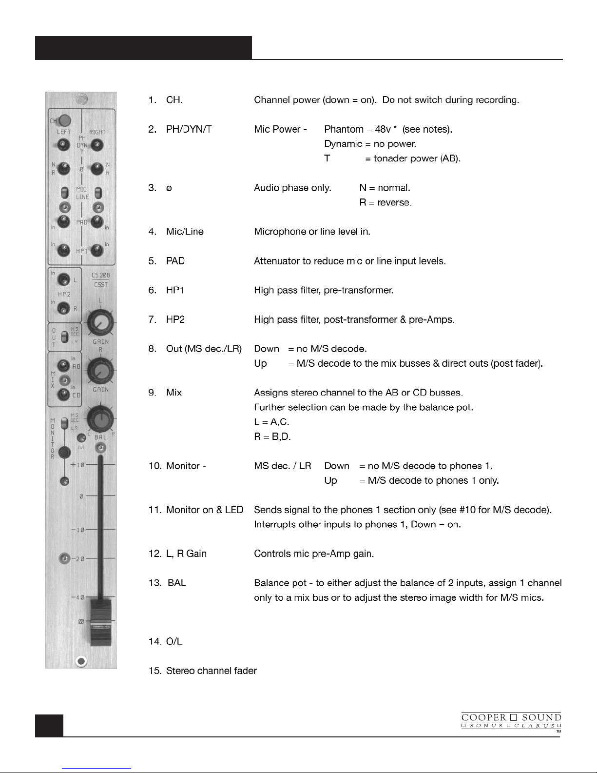
INPUT CHANNEL DESCRIPTION.............................................................................1, 2
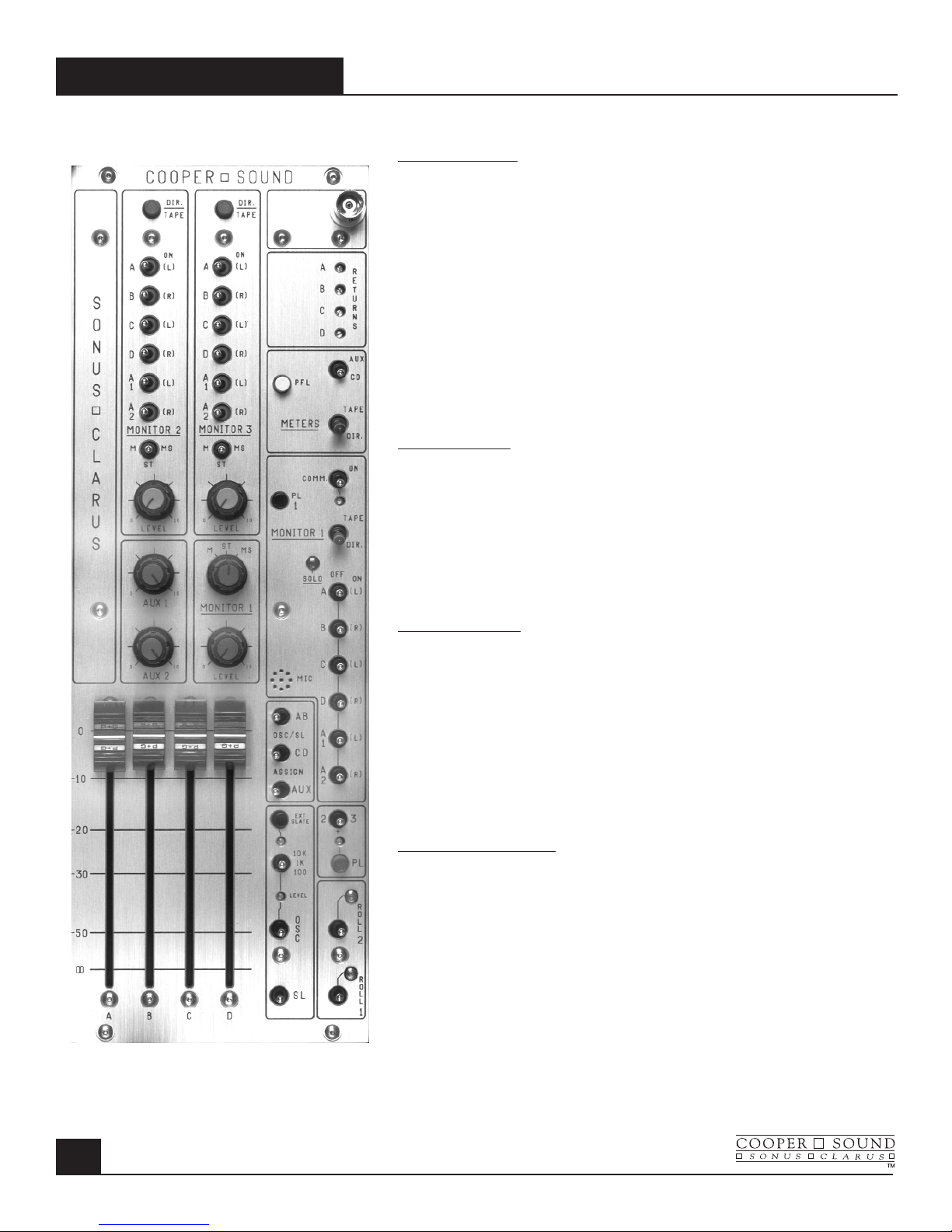
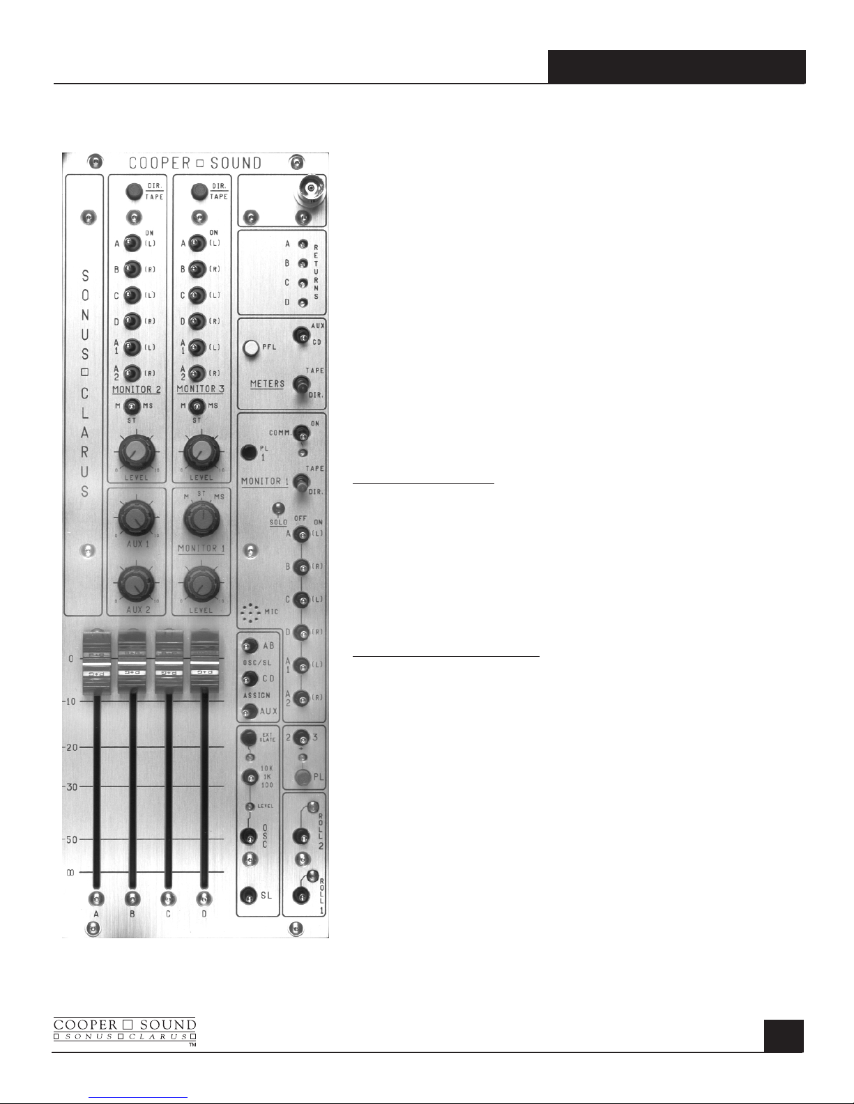
OUTPUT MODULE DESCRIPTION ..........................................................................3, 4
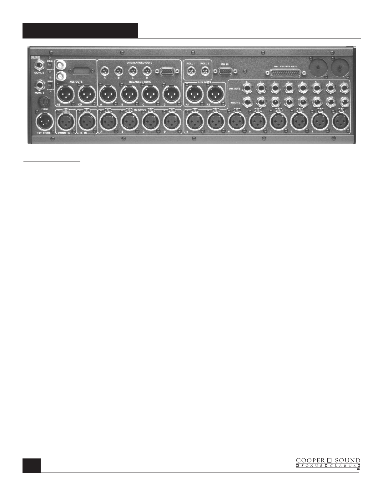
REAR PANEL DESCRIPTION .......................................................................................5
PIN OUTPUTS ...............................................................................................................6
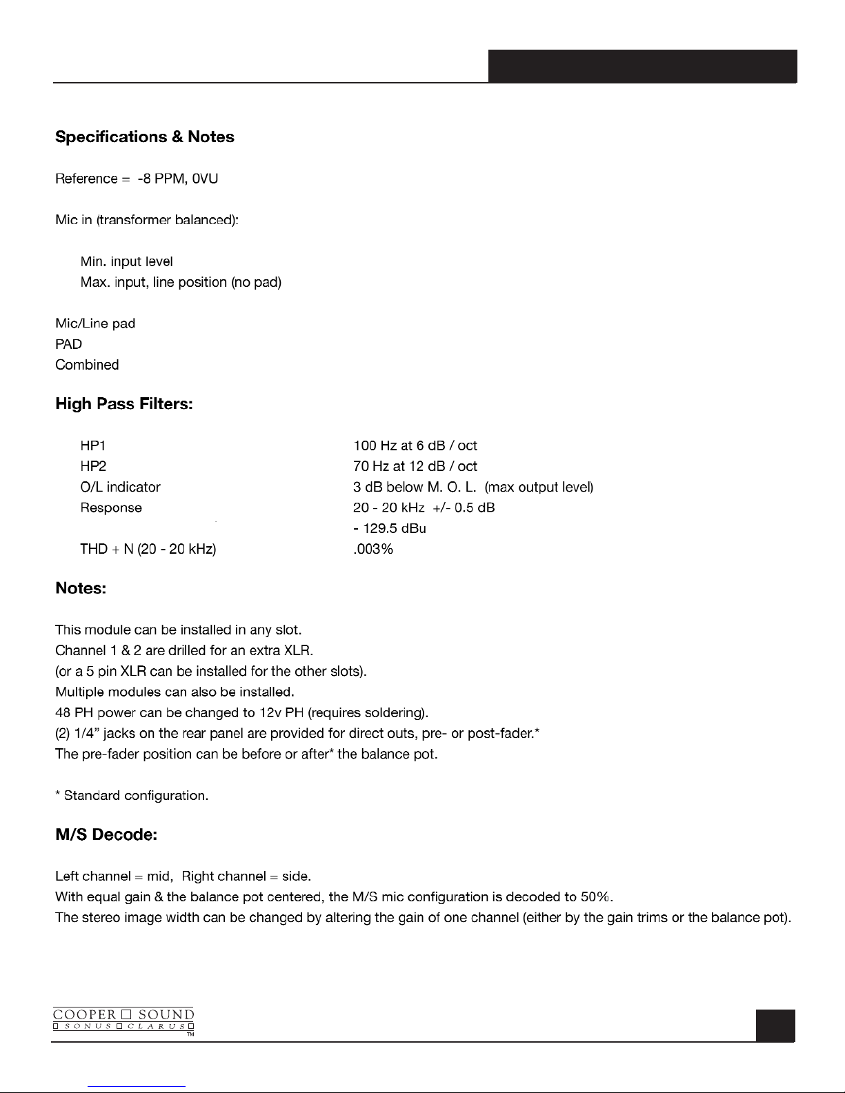
STEREO MODULE (OPTIONAL) ..............................................................................7, 8
SPECIFICATIONS
GENERAL ......................................................................................................................9
INPUTS ........................................................................................................................10
OUTPUTS.....................................................................................................................11
BLOCK DIAGRAM - INPUT & POWER WIRING.........................................................12
BLOCK DIAGRAM - OUTPUT .....................................................................................13
EQ CHARTS ................................................................................................................14
LAYOUT - A,B,C...........................................................................................................15
LAYOUT - D,E,F...........................................................................................................16
LAYOUT - G,G PPM, H, MB ........................................................................................17
CSST BLOCK DIAGRAM & LAYOUTS........................................................................18
BASIC SET UP & METERING...............................................................................19, 20
OPERATION & APPLICATION NOTES ...................................................21,22,23,24,25
APPLICATION NOTES
AN 1 v2 ROLLS............................................................................................................26
AN 2A INPUT CHANNEL OPTIONS............................................................................27
AN 2B v2 INPUT CHANNEL OPTIONS.......................................................................28
AN 2C v2 INPUT CHANNEL OPTIONS.......................................................................29
AN 2D v2 INPUT CHANNEL OPTIONS.......................................................................30
AN 2E v2 INPUT CHANNEL OPTIONS.......................................................................31
AN 3 v2 COMMUNICATIONS IN .................................................................................32
CABLE WIRING ...........................................................................................................33
GENERAL NOTES.......................................................................................................34
ADC OPTION - INSTRUCTIONS.................................................................................35
ADC OPTION - SPECIFICATIONS..............................................................................36
WARRANTY .................................................................................................................37

MODEL CS 208 v2
Left Section
1. CH: Channel Power (down = on) Do not switch during recording.
2. PH/DYN/T: Phantom power, no mic power, T (AB) power
(Phantom power is normally 48 v, see layout A to change to 12 v).
3. ø: Phase (audio only). ø = normal phase, REV = reverse phase
4. Mic/Line: Microphone or line level in.
5. Pad: Attenuator to reduce either mic or line input levels.
6. HP 1: High pass filter, pre-transformer.
7. HP 2: High pass filter, post transformer & preAmps.
8. EQ: Equalizer bypass. Affects HF, MF & LF filters, not HP filters.
9-12. A,B,C,D: Channel to mix bus assigns. L(left), R(right) indicate monitor & pan
pot assignment.
13. LIM+LED: The limiter is a symmetrical peak detecting type & is completely out
of circuit when switched off. Threshold: See (15). Attack & release
times are preset internally (see layout A to change). The LED
indicates limiter action.
14. PFL/AFL+LED: Pre fade listen or After fade listen (post fader). The switch is not
momentary, the LED serves as warning that PFL or AFL is
selected.
15. Thres. Limiter threshold. Clockwise = lower threshold.
16.O/L Near overload indicator.
INPUT MODULE
MAY 2003
1

MODEL CS 208 v2
MAY 2003
INPUT MODULE
2
Right Section
17. Gain: Mic/Line preamp gain.
18. HF: High frequency amplitude control.
19. MF 500, 5k Mid-frequency select.
20. MF: Mid-frequency amplitude control.
21. N/S: N = normal, S = side for M/S decoding.
‘S’inverts phase to B & D busses allowing one pair of channels to be
used with a M/S mic configuration and decoded to a L/R stereo signal
(this is an option, see separate application note).
22. LF: Low frequency amplitude control.
23. PF/AF: Selects pre or after fader for Aux 1 send.
24. A1: Aux 1 send (the aux sends are not affected by the ABCD mix bus
switches).
25. PF/AF: Selects pre or after fader for Aux 2 send.
26. A2: Aux 2 send.
27. Pan (switch): Switching the pan switch to the left disengages the panpot.
Crosstalk is therefore minimized and the output levels will remain equal.
28. Pan (pot): (L) = A & or C
(R) = B & or D
29. Channel fader

MODEL CS 208 v2
OUTPUT MODULE
MAY 2003
3
Monitor 2 & 3
1. DIR/TAPE: Selects direct or tape return signals (for
busses ABC & D).
2-7. A,B,C,D,A1,A2: Assigns busses to Monitor 2/3 outputs
(L) = left, (R) = right when using stereo
headphones.
8. M/ST/MS: M = mono, ST = stereo, MS = mid-side. Only
applicable if stereo headphones are used.
(See rear panel)
9. LEVEL: Gain Adjustment.
Aux 1, Aux 2
10,11.: Aux 1 & 2 master level controls.
12. BNC: 12 volts available to power a ‘Littlite’®
(See meter panel).
13. RETURNS: Trim pots (multiturn) to adjust return (tape)
level to Monitors 1, 2 & 3 and the meters.
Meter Section
14. AUX/CD Meters 3, 4 = CD or Aux outputs
(3 = C or A1, 4 = D or A2).
15. PFL: Meters 1, 2 can indicate PFL selected on the
input channels (momentary switch).
16. TAPE/DIR: Tape/Direct. Meters indicate the return sig-
nals. (1 = A, 2 = B, 3 = C, 4 = D). CD/Aux
switch (14) overrides the tape return.
Monitor 1 Section
17. COMM: Communications return (talkback) to Monitor
1 only (See appl. note for 2 returns). The
multiturn trimmer below this switch adjusts
the level.
18. PL 1: Private line assign to Monitor 1 (down = on).
See master PL switch #28.
19. TAPE/DIR: Tape or Direct to Monitor 1

20. SOLO/OFF/ON
A,B,C,D,A1,A2: Any combination of busses can be
monitored. ’SOLO’disconnects the other-
busses to the Monitor 1 output - Solo
normally mono’s the signal to the
headphone out - there is an internal slide
switch to defeat this. ‘ON’- In stereo mode
the busses are assigned to either (L) left or
(R) right.
21. M/ST/MS: M = mono, ST = stereo, MS = mid-side
(Monitor 1) Any combination selected by switch (20)
can be monitored in mono, stereo or
mid-side.
22. LEVEL: Gain control.
(Monitor 1)
23. MIC: Internal slate mic (See #24, 25, 27).
OSC/SL SECTION
24. AB/CD/AUX: Assigns the oscillator or slate to AB,CD or
Aux busses- The aux. bus switch now has
3 positions. Left = off, Center = Aux 1 only,
Right = Aux 1 & 2.
25. EXT SLATE: Down = external slate mic input (on rear
panel). The trimmer below adjusts the slate
mic level.
OSCILLATOR SECTION
26. 10k/1k/100: Frequency select for the internal oscillator.
LEVEL: Adjusts oscillator level (multiturn).
OSC: Internal oscillator - Up = on,
Down = momentary on.
27. SL: Slate mic; Down = with LF (low frequency)
tone. Up = no LF tone.
28. PL SECTION: Master private line to Monitors 1, 2 or 3.
The level is adjusted by the multiturn
trimmer above.
2/+/3: Assigns PL to Monitor 2, 2 & 3 or Monitor 3
only.
29. ROLL 1,2: Independent remote control for many types
of recorders (see separate application
note).
30. MASTER FADERS: ABCD - Normally left at maximum for
optimum headroom and signal to noise
ratio.
MODEL CS 208 v2
MAY 2003
OUTPUT MODULE
4

LEFT TO RIGHT
MONI 2, MONI 3: Monitor 2 & 3 outputs - for stereo or mono headphones
(or mono wireless communications).
FUSE: 2.5 A (5 x 20 mm).
EXT POWER: Pin 1 = negative DC, Pin 3 = Battery charge (positive),
Pin 4 = Positive DC (see specifications).
AES OUTS (Option) Digital outputs for A,B,C,D busses.
Clock reference in (upper BNC). Clock reference out (lower BNC)
UNBALANCED OUTS(TQG): A,B,C,D Pin 1 = ground, Pin 2 = signal.
UNBALANCED OUTS(DB9): A,B,C,D.
BALANCED OUTS(XLR): A,B,C,D, Aux 1, Aux 2.
ROLL 1 & 2: Remote control for various recorders.
MIX BUS IN: A,B,C,D (current input).
COMM IN: Communications input to Monitor 1 (balanced).
SL IN: External slate mic input.
RETURNS: A,B,C,D, balanced inputs.
BAL PREFADE OUTS(Option): Pre or post fader channel outputs (+4dBU balanced)
for multitrack recording (standard wiring).
DIR OUTS: Channel direct outs, post fader (unbalanced).
INSERTS: Can be changed to direct out, prefade (unbalanced). See Board A layout.
XLR Inputs: Transformer balanced (mic or line level).
2 spare holes: Stereo input channel option.
MODEL CS 208 v2
REAR PANEL
MAY 2003
5

MODEL CS 208 v2
MAY 2003
PIN OUTS
6
All XLR’s are wired pin 2 high. XLR 3M
Pin 1 = Ground
Pin 2 = High
Insert Pin 3 = Low
1/4”stereo jack Tip = Send
Ring = Return Phones 1, 2, 3
Sleeve = Ground 1/4”stereo jack (max load = 25Ωper channel)
or direct out, prefader Tip = Left
(see appl. note AN 2A & 2B v.2) Ring = Right
Sleeve = Ground
Direct Out Comm. In.
(post fader) XLR 3F
1/4”mono jack Tip = Signal Pin 2 = High
Sleeve = Ground Pin 3 = Low
Pin 1 = Ground
(See application note AN 3 v.2 for multiple inputs)
Mix Bus in
DB9 1 =Ground Returns
2 = D XLR 3F
3 = C Pin 2 = High
4 = A Pin 3 = Low
5 = B Pin 1 = Ground
(current input, see specifications)
Ext. Slate in
Outputs XLR 3F
DB9 1 = Ground Pin 2 = Signal
2 = A Pin 3 & 1 = Ground
3 = B
4 = C DB25 Balanced Outputs (Option)
5 = D Pin Pin
Ch.1 Hot 24 Ch.5 Hot 18
TQG 3M Cold 12 Cold 6
Pin 1 = Ground Ground 25 Ground 19
Pin 2 = Signal
Pin 3 = N/C Ch.2 Hot 10 Ch.6 Hot 4
Cold 23 Cold 17
TQG 5M (roll) (See application note AN 1 v.2) Ground 11 Ground 5
Pin 1 = -10 v (Nagra)
Pin 2 = Stop (Nagra) Ch.3 Hot 21 Ch.7 Hot 15
Pin 3 = Pause/Stop (DATs) Cold 9 Cold 3
Pin 4 = Common (DATs) Ground 22 Ground 16
Pin 5 = Record (DATs)
Ch.4 Hot 7 Ch.8 Hot 1
Cold 20 Cold 14
Ground 8 Ground 2

MODEL CS 208 v2
CSST-STEREO MODULE
MAY 2003
7
Overload indicator.

MODEL CS 208 v2
MAY 2003
CSST-STEREO MODULE
8
-83 dBu (Z = 1.4kΩ)
+28 dBu
-40 dB Zin≈10kΩ
-15 dB Zin≈600Ω
-55 dB Zin≈10kΩ
EIN (20 - 20 kHz,150Ω)

MODEL CS 208 v2
SPECIFICATIONS
MAY 2003
9
General: (0 dBu ≈.775v RMS)
Dimensions 16.5”x 15.2”x 5”(419 x 386 x 127 mm)
Weight with no batteries 19 lbs. (8.6 kg)
with alkaline cells 23lbs. (10.4 kg)
Overall distortion (THD + N) < 0.01% (0.003% typ.)
Equivalent input noise (150Ω20-20kHz) -129.5 dBu
(150Ω‘A’WT’D) -131.2 dBu
Power Requirements:
External: 10v - 25v operating range.
Consumption with all channels on is ≈630 mA at 12v DC < 8 watts (410 mA at 18v DC)
Estimated battery life with 12v, 8 AH lead acid battery > 10 hours.
12v, 12 AH lead acid battery > 15 hours.
18v, 14 AH alkaline cells > 15 hours.
(Ni-CAD D cells are ≈1/3 the capacity of alkaline cells.)
XLR - 4M:
1 = Ground (-)
2 = N/C
*3 = Battery charge (+)
4 = External in (+) * Do not connect if rechargeable batteries are not installed.
Internal Power: 12 ‘D’alkaline cells
PPM VU Nordic
Battery test: + 18v DC = +2 +3 Full Scale (Last mark)
+ 12v DC = -6 0 +4
+ 10.5v DC= -8 -1 +2
BNC light: +12v out, 500 mA max. (1815 bulb ≈180 mA).
Power on LED: Turns off when the voltage is 11v or less.
Power cut off voltage: ≈10v DC (internal supply switches off).
48v Phantom: 48v +/- 1v.
12v T: 12v +/- 1v.

MODEL CS 208 v2
MAY 2003
SPECIFICATIONS
10
System Power Connections and Precautions:
RE: (+) chassis equipment.
The Nagra must have a separate supply, with no common power supply connections to the mixer or other (-)
chassis equipment.
Input:
Reference: -8PPM, 0VU (XLR’s are pin 2 high).
Mic In: (Transformer balanced)
Minimum input level -83 dBu (Z in 1.4k Ω)
Maximum input, line position (no pad) +28 dBu (Z in 10k Ω)
Pad 15 dB Z in ≈600Ω
Mic/Line 40 dB Z in ≈10kΩ
Combined 55 dB Z in ≈10kΩ
High Pass Filters:
Hp 1 Pre - transformer 100Hz -6 dB/oct.
Hp 2 Post - transformer & pre Amp. 70Hz -12 dB/oct.
EQ:
High frequency +/- 12 dB @ 10 kHz
Mid frequency +/- 15 dB 500 - 5 kHz
Low frequency +/- 12 dB @ 100 Hz
Insert: Send/direct out, pre-fader -11 dBu Zout = 47Ω(+4 dBu with boost)
Return -11 dBu Zin ≈5kΩ
Direct out (post-fader): -8 dBu Zout = 47Ω
O/L indicator: -3 dB MOL
Limiter:
Threshold Variable* -6 PPM to M. O. L. (+4 PPM typ.)
Attack 1 ms
Release 150 ms
(M. O. L. = maximum output level = 25 dBu on XLR outs, +19 dBu on unbalanced outs.)
Pan pots: Center = -3 dB
All specifications are measured with the pan pots panned either L or R.

MODEL CS 208 v2
SPECIFICATIONS
MAY 2003
11
Output:
Reference -8 PPM, 0VU (XLR’s are pin 2 high)
XLR balanced outputs:
A, B, C, D & Aux. 1, 2 +4 dBu, Zout ≈100Ω
TQG & DB 9 unbalanced outputs:
(ABCD) -2 dBu, Zout ≈100Ω
Phones 1 out: 0 dBu no load
0 dBu 60Ωload
Phones 2 &3: -3 dBu no load
-8 dBu 60Ωload
Maximum load is 25Ωfor each output:
Tape return (balanced) -14 dBu to + 19 dBu Zin = 10kΩ
Communication in (balanced) -14 dBu to + 19 dBu Zin = 10kΩ
Ext. slate in (unbalanced) -60 dBu to - 38 dBu Zin = 5kΩ
Mix bus in - current input - R. series 10kΩ-8 dBu (-10 dBV)
20kΩ-2 dBu
(needs series resistors) 40kΩ+4 dBu
Signal (M. O. L.) to noise of output section:
(Dynamic range)
(Channel faders off, masters at max) -115 dB 20-20 kHZ
Slate subtone 27 Hz (at -16 PPM, -8vu)

MODEL CS 208 v2
MAY 2003
BLOCK DIAGRAM
12
INPUT & POWER

MODEL CS 208 v2
BLOCK DIAGRAM
MAY 2003
13
MONITOR & OUTPUT

MODEL CS 208 v2
MAY 2003
EQ CHARTS
14

MODEL CS 208 v2
LAYOUTS
MAY 2003
15

MODEL CS 208 v2
MAY 2003
LAYOUTS
16

MODEL CS 208 v2
LAYOUTS
MAY 2003
17

MODEL CS 208 v2
MAY 2003
CSST - LAYOUTS
18
Table of contents
Other Cooper Sound Music Mixer manuals