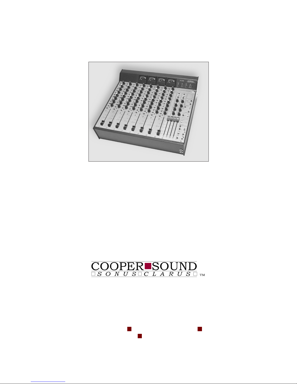
Cooper Sound CS 208 User manual

CS 208 PROFESSIONAL AUDIO MIXER
1411 Marsh Street, Suite 105 !San Luis Obispo, CA 93401 !(805) 782-9750 !Fax: (805) 782-9752
www.coopersound.com
OPERATOR’S MANUAL
645 Main Street, Suite C
Morro Bay
CA
Phone: (805) 772-1007
Fax: (805) 772-1098
,
http://www.coopersound.com
93442-2273
USA
Cover Page
Cover Page

CS208
Cooper Sound Systems, Inc.
TABLE OF CONTENTS
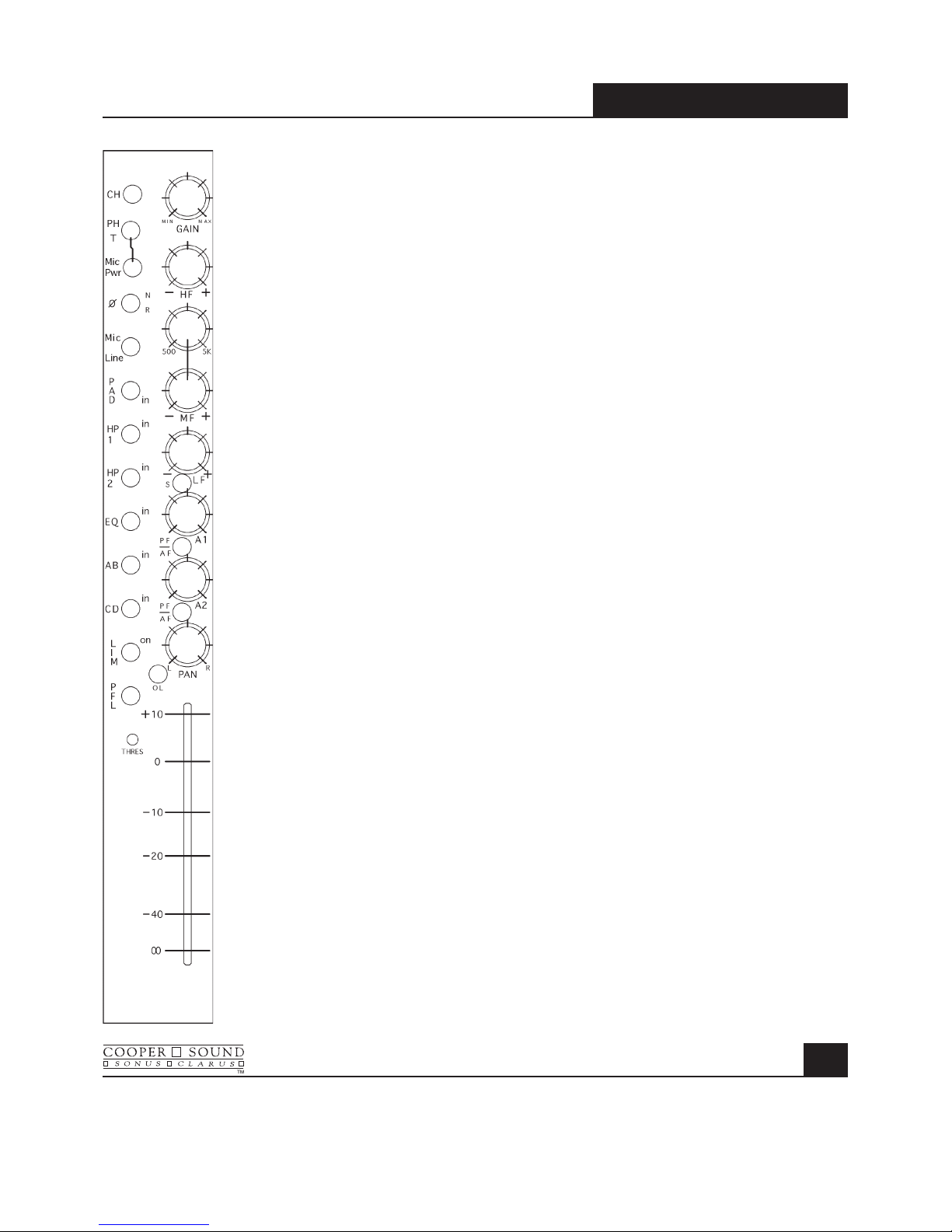
INPUT CHANNEL DESCRIPTION ............................................................1, 2
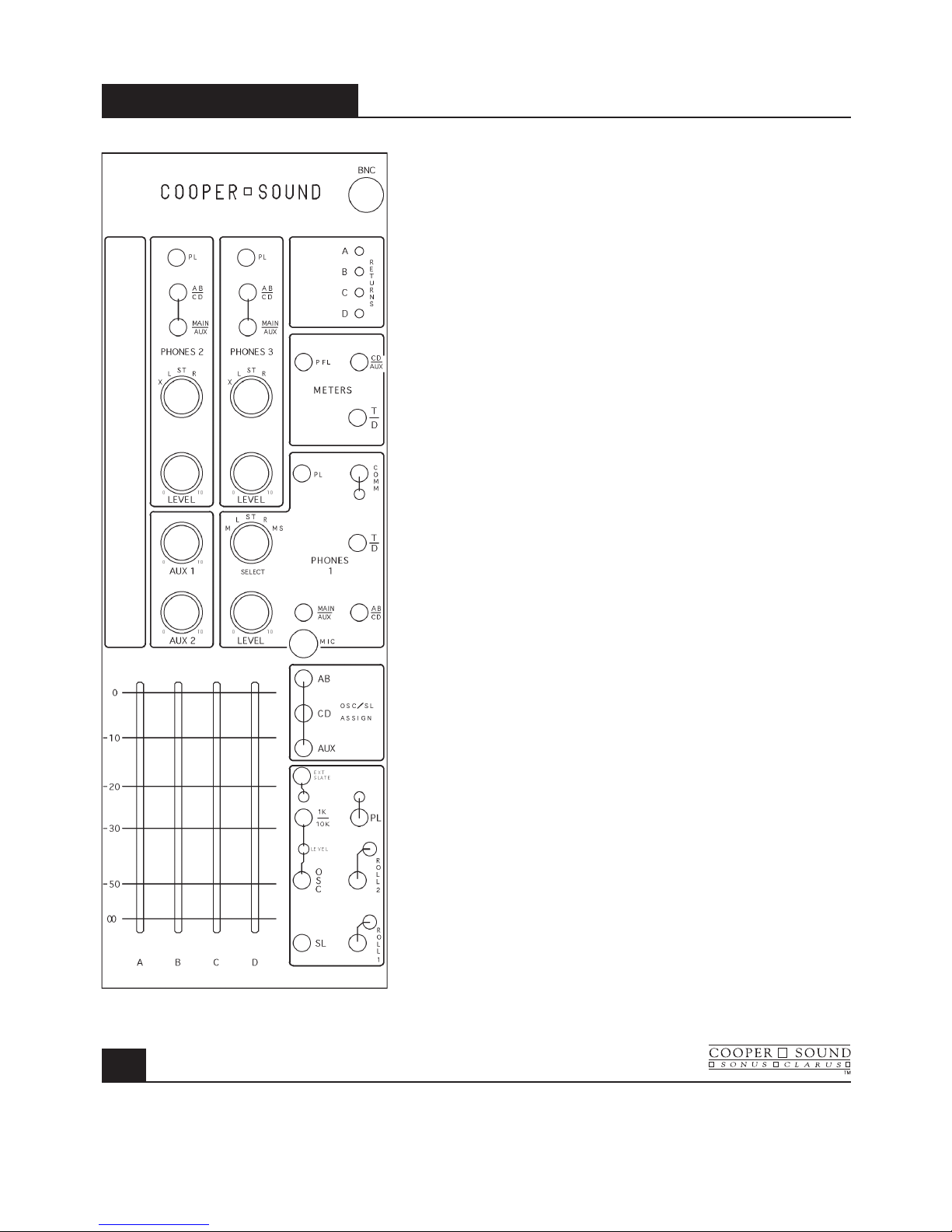
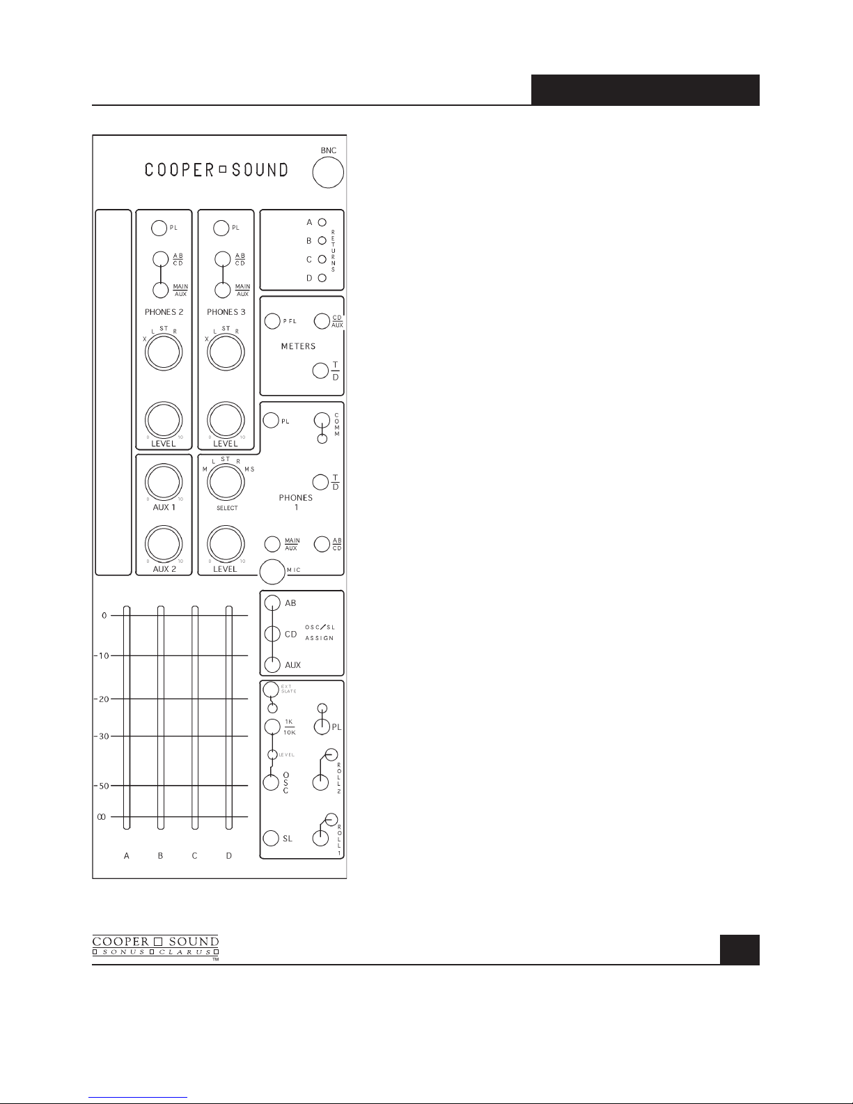
OUTPUT MODULE DESCRIPTION ..........................................................3, 4
REAR PANEL DESCRIPTION ....................................................................... 5
PIN OUTS ..................................................................................................... 6
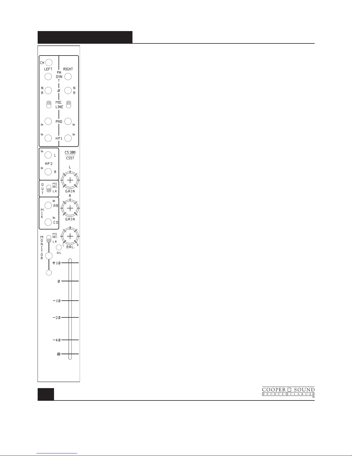
STEREO MODULE (OPTIONAL)............................................................... 7, 8
SPECIFICATIONS
GENERAL. ............................................................................................. 9
INPUTS ................................................................................................. 10
OUTPUTS ............................................................................................. 11
BLOCK DIAGRAM - INPUT & POWER WIRING .......................................... 12
BLOCK DIAGRAM - OUTPUT ...................................................................... 13
EQ CHARTS ................................................................................................ 14
LAYOUT - A, B, C ......................................................................................... 15
LAYOUT - D, E, MB ...................................................................................... 16
LAYOUT - F, G, G PPM, H ........................................................................... 17
CSST BLOCK DIAGRAM & LAYOUTS ........................................................ 18
BASIC SET UP & METERING................................................................. 19, 20
OPERATION & APPLICATION NOTES ................................. 21, 22, 23, 24, 25
APPLICATION NOTES
AN 1 ROLLS ................................................................................................ 26
AN 2A INPUT CHANNEL OPTIONS ............................................................ 27
AN 2B INPUT CHANNEL OPTIONS ............................................................ 28
AN 2C INPUT CHANNEL OPTIONS ............................................................ 29
AN 2D INPUT CHANNEL OPTIONS ............................................................ 30
AN 2E INPUT CHANNEL OPTIONS ............................................................ 31
AN 3 COMMUNICATIONS IN ...................................................................... 32
GENERAL NOTES ........................................................................................ 33
WARRANTY.................................................................................................. 34
Table of Content
Table of Content

Left Section
1. CH : Channel Power (down = on) Do not switch during recording.
2. PH / T : Phantom Power, ‘T’ power (AB). (phantom power is normally 48v, see layout A
to change to 12v).
3. Mic Pwr : Turns on mic power (down = on).
Mic power type selected by the switch above.
4. ø : N = normal, R = reverse. Audio phase only.
5. Mic / Line : Microphone or line level in.
6. Pad : Attenuator to reduce either mic or line input levels.
7. HP1 : High pass filter, pre-transformer.
8. HP2 : High pass filter, post transformer & preAmps.
9. EQ : Equalizer bypass. Affects HF, MF & LF filters, not HP filters.
10. AB : Assigns channel to AB mix busses.
Further selection is made by the pan pot. A = L, B = R.
11. CD : Assigns channel to CD mix busses.
Further selection is made by the pan pot. C = L, D = R.
12. Lim : The limiter is a symmetrical peak detecting type & is completely out of circut
when switched off. Threshold: See (14). Attack & release times are preset
internally (see layout A to change).
13. PFL : Pre-fade listen.
Sends selected channel to phones 1 only.
(Cuts out all other inputs to phones).
Can be changed to AFL (see layout A).
14. Thres : Limiter threshold. Clockwise = lower threshold.
15. O / L : Near overload or limiter threshold indicator (see layout A).
INPUT MODULE MODEL CS 208
1
Left Page
Left Page

INPUT MODULE
MODEL CS 208
2
Right Section
16. Gain : Mic / Line preAmp gain.
17. HF : High frequency amplitude control.
18. MF 500, 5k : Mid-frequency select.
19. MF : Mid-frequency amplitude control.
20. LF : Low frequency amplitude control.
21. S : Invert phase option to B & D busses. 1 pair of channels could be used
to decode a M / S microphone configuration.
22. A1 : Aux 1 send (the aux sends are not affected by the AB,
CD mix bus switches).
23. PF / AF : Selects pre or after fader for Aux 1 send.
24. A2 : Aux 2 send.
25. PF / AF : Selects pre or after fader for Aux 2 send.
26. Pan : L = A and/or C, R = B and/or D.
Example: A out only. AB switch in, CD switch out,
Pan L (left).
27. Channel fader.
See specifications & application notes for further details.
Right Page
Right Page

OUTPUT MODULE MODEL CS 208
3
Phones 2 & 3
1. PL : Private line assign to phones 2 or 3
(down = on). See master PL switch (27).
2. Main/Aux : Selects main (ABCD) or Aux 1 & 2 to
phones 2 or 3.
(Aux 1 = L out, Aux 2 = R out.)
3. AB / CD : When main is selected, this switch selects
either AB or CD to L, R of the phone outs.
4. Rotary Select Switch :
X = phones 2 or 3 follows the phones 1 selection.
Example: Playback to phones 2 & 3 for director/
script critique. (Switch phones 1 to tape).
L = A, C or A1 to both outputs. (ie: Mono to L & R
headphone capsules). See (2 & 3).
ST = A, C, A1 to left capsule B, D, A2 to right
capsule. See (2 & 3).
R = B, D, A2 to both outputs. See (2 & 3).
5. Phones 2/3 level :
Gain adjustment.
Aux 1, Aux 2
6. Aux 1, 2 master level controls.
Returns
7. Trim pots (multi-turn) to adjust return (tape) level to
phones 1 & meters.
Meter Section
8. CD/Aux : Meters 3, 4 = CD or Aux outputs
(3 = C or A1, 4 = D or A2).
9. PFL : Meters 1, 2 can indicate PFL selected on the input
channels. (Momentary switch).
10. T/D : Tape/Direct. Meters indicate the return signals.
(1 = A, 2 = B, 3 = C, 4 = D). CD/Aux switch (8)
overides the tape return.
Phones 1
11. PL : Private line assign to phones 1 (down = on) see master
PL switch (27).
12. Comm : Communications return to phones 1 only. (down = on).
(Talkback to phones 1) (see app. notes for 2 returns).
Left Page
Left Page

13. Comm. Trimmer : Adjusts return level.
14. T / D : Tape or direct to phones 1.
See AB / CD below (16).
15. Main / Aux : Selects either main, ABCD or Aux (A1, A2)
to phones 1.
16. AB / CD : When main is selected, group AB or CD
is sub-selected to phones 1. This also controls
the tape return (A = L, B = R, C = L, D = R).
17. Phones 1 selector :
M = Mono to both outputs.
L = A, C or A1 mono to both outputs.
ST = A, C, A1 = L. B, D, A2 = R.
R = B, D, A2 mono to both outputs.
M.S. = M/S decode to phones 1.
18. Level : Phones 1 gain control.
Mic
19. Internal slate microphone (See Ext. Slate) (21).
OSC/SL Assign
20. Assigns oscillator & slate to AB, CD or Aux outputs.
OSC, SL, PL, Roll
21. Ext. Slate : Selects internal or external slate mic.
Down = external slate input on rear panel.
(Bypasses internal slate mic).
22. Slate Trimmer : Controls level of both Int. & Ext. slate
(multi-turn pot).
23. 1k / 10k : Frequency select for internal oscillator.
Up = 1kHz, down = 10k.
24. Trimmer : Oscillator level (multi-turn pot).
25. Osc : Internal oscillator.
(up = on, down = momentary on).
26. SL : Slate mic.
down = with LF tone, up = no LF tone.
27. PL : Master private line & level control.
Directs slate mic to phones 1, 2, 3 only.
Assigned by (1 & 11).
28. Roll 1 & 2 : Up = on, down = pause or stop.
See “pin outs” for further details.
OUTPUT MODULE
MODEL CS 208
4
Right Page
Right Page

REAR PANEL MODEL CS 208
5
1. Phones 2 : Stereo 1/4” jack.
2. Phones 3 : Stereo 1/4” jack.
3. Fuse : 2.5A (5 x 20mm).
4. Ext. Power In : Pin 1 = negative DC, Pin 3 = Battery charge (positive), Pin 4 = Positive DC
(see specifications).
5. A, B, C, D, A1, A2 : Balanced XLR outputs (Pin 2 high)
6. Unbalanced Outs (TQG) : ABCD Pin 1 = ground, Pin 2 = signal.
7. Unbalanced Outs (DB9) : ABCD.
8. Mix Bus In : ABCD (current input).
9. Comm. In : Talkback to phones 1. Balanced input. Stereo 1/4” jack.
10. Slate : External slate mic input. Mono 1/4” jack.
11. Roll 1, 2 : See pin outs.
12. Returns : ABCD Balanced in. Stereo 1/4” jack.
13. Ch. Dir. Out : Channel direct out, post fader. Mono 1/4” jack.
14. Ch. Insert : Can be direct out, pre-fader (see board A layout). Unbalanced stereo 1/4” jack.
15. 2 spare holes : Option for stereo input channels.
Left Page
Left Page

PIN OUTS
MODEL CS 208
6
All XLR’s are wired pin 2 high and are
transformer balanced.
Insert
1/4” stereo jack Tip = Send
Ring = Return
Sleeve = Ground
or direct out, pre-fader
(see app. note AN 2A & 2B)
Direct Out
(post-fader)
1/4” mono jack Tip = Signal
Sleeve = Ground
Mix Bus In
DB9 1 = Ground
2 = D
3 = C
4 = A
5 = B
(current input, see specifications)
Outputs
DB9 1 = Ground
2 = A
3 = B
4 = C
5 = D
TQG 3M
Pin 1 = Ground
Pin 2 = Signal
Pin 3 = N/C
TQG 5M (roll) (See application note AN 1)
Pin1 = -10 v (Nagra)
Pin 2 = Stop (Nagra)
Pin 3 = Pause/Stop (DATs)
Pin 4 = Common (DATs)
Pin 5 = Record (DATs)
XLR 3M
Pin 1 = Ground
Pin 2 = High
Pin 3 = Low
Phones 1, 2, 3
1/4” stereo jack (max load = 25!per channel)
Tip = Left
Ring = Right
Sleeve = Ground
Comm. In
1/4” stereo jack
Tip = High
Ring = Low
Sleeve = Ground
(See application note AN 3 for multiple inputs)
Returns
1/4” stereo jack
Tip = High
Ring = Low
Sleeve = Ground
Ext. Slate In
1/4” mono/stereo jack
Tip = Signal
Ring & Sleeve = Ground
Right Page
Right Page

CSST-STERE0 MODULE
MODEL CS 208
7
1. CH. Channel power (down = on). Do not switch during recording.
2. PH/DYN/T Mic Power - Phantom = 48v * (see notes).
Dynamic = no power.
T = tonader power (AB).
3. ø Audio phase only. N = normal.
R = reverse.
4. Mic/Line Microphone or line level in.
5. PAD Attenuator to reduce mic or line input levels.
6. HP1 High pass filter, pre-transformer.
7. HP2 High pass filter, post-transformer & pre-Amps.
8. Out (MS dec./LR) Down = no M/S decode.
Up = M/S decode to the mix busses & direct outs (post fader).
9. Mix Assigns stereo channel to the AB or CD busses.
Further selection can be made by the balance pot.
L = A,C.
R = B,D.
10. Monitor - MS dec. / LR Down = no M/S decode to phones 1.
Up = M/S decode to phones 1 only.
11. Monitor on & LED Sends signal to the phones 1 section only (see #10 for M/S decode).
Interrupts other inputs to phones 1, Down = on.
12. L, R Gain Controls mic pre-Amp gain.
13. BAL Balance pot - to either adjust the balance of 2 inputs, assign 1 channel
only to a mix bus or to adjust the stereo image width for M/S mics.
14. O/L Overload indicator.
15. Stereo channel fader
Left Page
Left Page

Specifications & Notes
Reference = -8 PPM, 0VU
Mic in (transformer balanced):
Min. input level -83 dBu (Z in = 1.4 k!)
Max. input, line position (no pad) +28 dBu
Mic/Line pad -40 dB Zin "10k!
PAD -15 dB Zin "600!
Combined -55 dB Zin "10k!
High Pass Filters:
HP1 100 Hz at 6 dB / oct
HP2 70 Hz at 12 dB / oct
O/L indicator 3 dB below M. O. L. (max output level)
Response 20 - 20 kHz +/- 0.5 dB
EIN (20 - 20 kHz, 150!) - 129.5 dBu
THD + N (20 - 20 kHz) .003%
Notes:
This module can be installed in any slot.
Channel 1 & 2 are drilled for an extra XLR.
(or a 5 pin XLR can be installed for the other slots).
Multiple modules can also be installed.
48 PH power can be changed to 12v PH (requires soldering).
(2) 1/4” jacks on the rear panel are provided for direct outs, pre- or post-fader.*
The pre-fader position can be before or after* the balance pot.
* Standard configuration.
M/S Decode:
Left channel = mid, Right channel = side.
With equal gain & the balance pot centered, the M/S mic configuration is decoded to 50%.
The stereo image width can be changed by altering the gain of one channel (either by the gain trims or the balance pot).
CSST-STERE0 MODULE
MODEL CS 208
8
Right Page
Right Page

SPECIFICATIONS
MODEL CS 208
9
General: (0 dBu !.775v RMS)
Dimensions 16.5” x 15” x 5” (419 x 381 x 127 mm)
Weight with no batteries 19 lbs. (8.6 kg)
with alkaline cells 23lbs. (10.4 kg)
Overall distortion (THD + N) < 0.01% (0.003% typ.)
Equivalent input noise (150"20-20kHz) -129.5 dBu
(150"‘A’ WT’D) -131.2 dBu
Power Requirements:
External: 10v - 25v operating range.
Consumption with all channels on is !630 mA at 12v DC < 8 watts (410 mA at 18v DC).
Estimated battery life with 12v, 8 AH lead acid battery > 10 hours.
12v, 12 AH lead acid battery > 15 hours.
18v, 14 AH alkaline cells > 15 hours.
(Ni-CAD D cells are !1/3 the capacity of alkaline cells.)
XLR - 4M:
1 = Ground (-)
2 = N/C
*3 = Battery charge (+) * Do not connect if rechargeable batteries are not installed.
4 = External in (+)
Internal Power: 12 ‘D’ alkaline cells
PPM VU
Battery test: + 18v DC = +2 +3
+ 12v DC = -6 0
+ 10.5v DC= -8 -1
BNC light: +12v out, 500 mA max. (1815 bulb !180 mA).
Power on LED: Turns off when the voltage is 11v or less.
Power cut off voltage: !10v DC (internal supply switches off).
48v Phantom: 48v +/- 1v.
12v T: 12v +/- 1v.
Left Page
Left Page

SPECIFICATIONS
MODEL CS 208
10
System Power Connections and Precautions:
RE: (+) chassis equipment.
The Nagra 4.2, IVS must have a separate supply, with no common power supply connections to the mixer or other (-)
chassis equipment.
Input:
Reference: -8PPM, 0VU (XLR’s are pin 2 high).
Mic In: (Transformer balanced)
Minimum input level -83 dBu (Z in 1.4k !)
Maximum input, line position (no pad) +28 dBu (Z in 10k !)
Pad 15 dB Z in "600!
Mic/Line 40 dB Z in "10k!
Combined 55 dB Z in "10k!
High Pass Filters:
Hp 1 Pre-transformer 100Hz -6 dB/oct.
Hp 2 Post-transformer & pre-Amp. 70Hz -12 dB/oct.
EQ:
High frequency +/- 12 dB @ 10 kHz
Mid frequency +/- 15 dB 500 - 5 kHz
Low frequency +/- 12 dB @ 100 Hz
Insert: Send/direct out, pre-fader -5 dBu Zout
= 47!(+4 dBu with boost)
Return -5 dBu Zin = 5k!
Direct out (post-fader): -2 dBu Zout
= 47!
O/L indicator: -3 dB MOL
Limiter:
Threshold Variable* -6 PPM to M. O. L. (+4 PPM typ.)
Attack Slow 100 ms
Fast* 10 ms
Release Slow 500 ms
Fast* 100 ms
* Standard Setting
(M. O. L. = maximum output level = 25 dBu on XLR outs, +19 dBu on unbalanced outs.)
Pan pots: Center = -3 dB
All specifications are measured with the pan pots panned either L or R.
Right Page
Right Page

Output:
Reference -8 PPM, 0VU (XLR’s are pin 2 high)
XLR balanced outputs:
A, B, C, D & Aux. 1, 2 +4 dBu, Zout
!100"
TQG & DB 9 unbalanced outputs:
(ABCD) -2 dBu, Zout !100"
Phones 1 out: 0 dBu no load
0 dBu 60"load
Phones 2 &3: -3 dBu no load
-8 dBu 60"load
Maximum load is 25"for each output:
Tape return (balanced) -14 dBu to + 19 dBu Zin = 10k"
Communication in (balanced) -14 dBu to + 19 dBu Zin = 10k"
Ext. slate in (unbalanced) -60 dBu to - 38 dBu Zin = 5k"
Mix bus in - current input - R. series 5k"-8 dBu (-10 dBV)
10k"-2 dBu
(needs series resistors) 20k"+4 dBu
Signal (M. O. L.) to noise of output section:
(Dynamic range)
(Channel faders off, masters at max) -115 dB 20-20 kHZ
Slate subtone 27 Hz (at -16 PPM, -8vu)
SPECIFICATIONS
MODEL CS 208
11
Left Page
Left Page

BLOCK DIAGRAM
MODEL CS 208
12
Right Page
Right Page

BLOCK DIAGRAM
MODEL CS 208
13
Left Page
Left Page

EQ CHARTS
MODEL CS 208
14
1=HP 1
2=HP 2
3=HP 1 + HP 2
2
1
3
Right Page
Right Page

LAYOUTS
MODEL CS 208
15
Left Page
Left Page

MODEL CS 208
16
LAYOUTS
Right Page
Right Page

LAYOUTS
MODEL CS 208
17
Left Page
Left Page

CSST - LAYOUTS
MODEL CS 208
18
Right Page
Right Page
Table of contents
Other Cooper Sound Music Mixer manuals