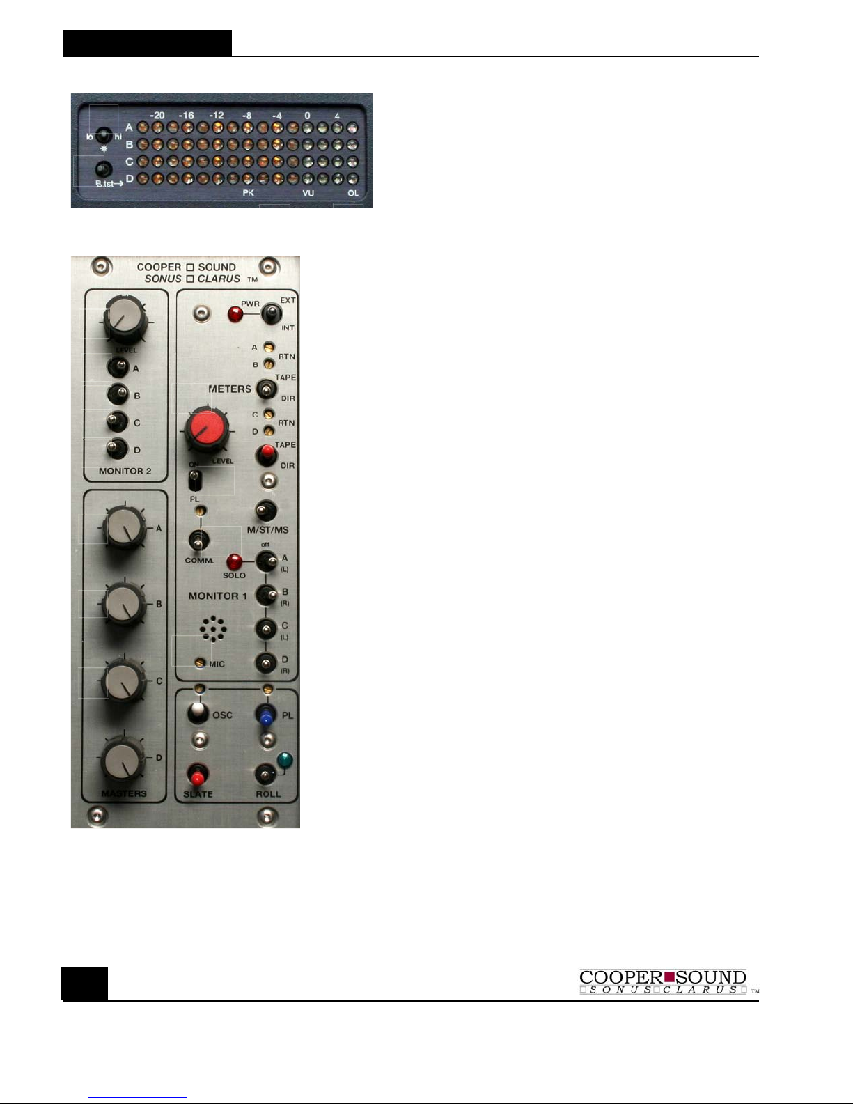
Meters:
1. Controls LED brightness. Use lowest
setting possible to conserve current
consumption.
2. B. TST: Battery test (see specs)
3. PK/VU: The mixer is configured for either VU
or Peak response meters.
PK: The reference tone is at -8 dB
VU: The reference tone is at 0 dB.
4. OL: ‘Overload’ - Indicates near clip level. This
LED has a slower release time than the
others.
MONITOR 2
1. Level: Monitor 2 gain adjustment
2-5. A,B,C,D Assigns busses to Monitor 2 output
6-9. Master Faders: ABCD - Normally left at maximum for
optimum headroom & signal to noise ratio.
10. Level (monitor 1):Gain adjustment
11. PL: Private line assign to Monitor 1
12. COMM: Communications return (talkback) to Monitor
1 only (See application note for 2 returns)
The multiturn trimmer above this Switch
adjusts the level.
13. MIC: Internal slate mic & gain adjustment
14. TAPE/DIR : (monitor 1) Tape or Direct to Monitor 1
15. M/ST/MS : (monitor 1) M = mono, ST = stereo, MS = mid-side
Any combination selected by switches
(16-19) can be monitored in mono, stereo
or mid-side.
16-19. SOLO/OFF/ON Any combination of busses can be
A,B,C,D: monitored. ‘SOLO’ disconnects the other
busses to the Monitor 1 output - Solo
mono’s the signal to the headphone out.
‘ON’ - In stereo mode the busses are
assigned to either (L) left or (R) right.
20. Power: Internal or external power (center off)
(LED: Turns off at minimum input voltage.)
21,23. Returns: Trim pots (multiturn) to adjust return (tape)
level to Monitor 1 and the meters
22. TAPE/DIR : (meters) Tape/Direct: Meters indicate the return
signals.
OSCILLATOR SECTION
24. OSC: Internal oscillator: Up = on, Down = momentary on.
Trimmer (multiturn) above adjusts level
25. Slate: Slate mic on
26. PL: Private line to Monitors 1 & 2. The level is
adjusted by the multiturn trimmer above. (See #11)
27. Roll: Remote control for many types of recorders (see
separate application note).
Up = Roll; Down = Stop/Pause