NS NH
EOLR
+
-
SM
F
A
C
P
STROBE
Audible
STROBE
+
-Audible
Audible
NAC
Circuit
Strobe
NAC
Circuit
SIGNAL
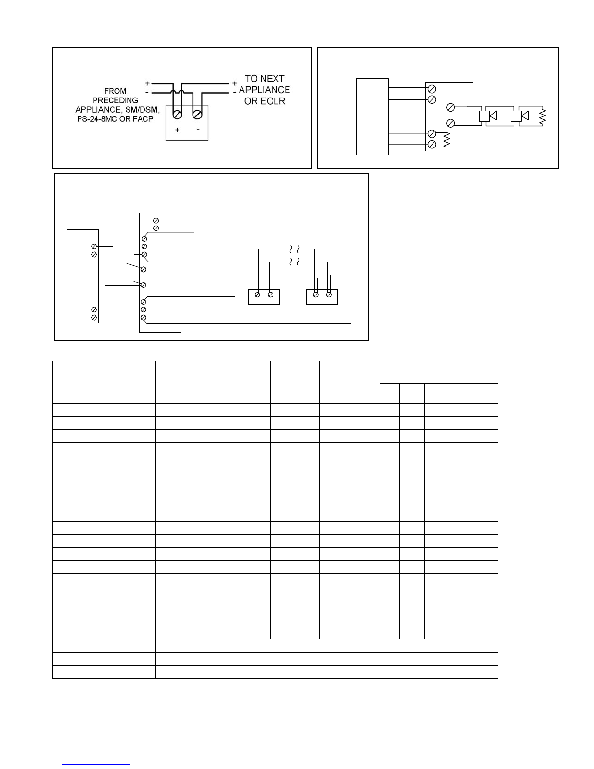
ZNS/ZNH APPLIANCE
ZNS AND ZNH APPLIANCES SYNCHRONIZED WITH DSM MODULE
DUAL CLASS “A” NAC CIRCUIT WITH NO AUDIBLE SILENCE FEATURE
Wiring Diagrams#
NOTE: ZNS/ZNH must be set on Code-3 horn tone
to achieve synchronized temporal (Code-3) tone.
Refer to installation instruction (P83983, P83600
respectively).
ZNS AND ZNH APPLIANCES SYNCHRONIZED WITH SM MOD-
ULE SINGLE CLASS “B” NAC CIRCUIT WITH AUDIBLE SILENCE
FEATURE
# For detail using SM or DSM Sync Module refer
to Data Sheet S3000 or Installation Instructions
P83123 for SM and P83177 for DSM. For
wiring information on the power supplies refer to
Installation Instructions P84662 for PS-24-8MC.
NOTE: Due to continuous development of our products, specifications and offerings are subject to change without notice in accordance
with Wheelock Inc. standard terms and conditions.
SPECIFICATION & ORDERING INFORMATION
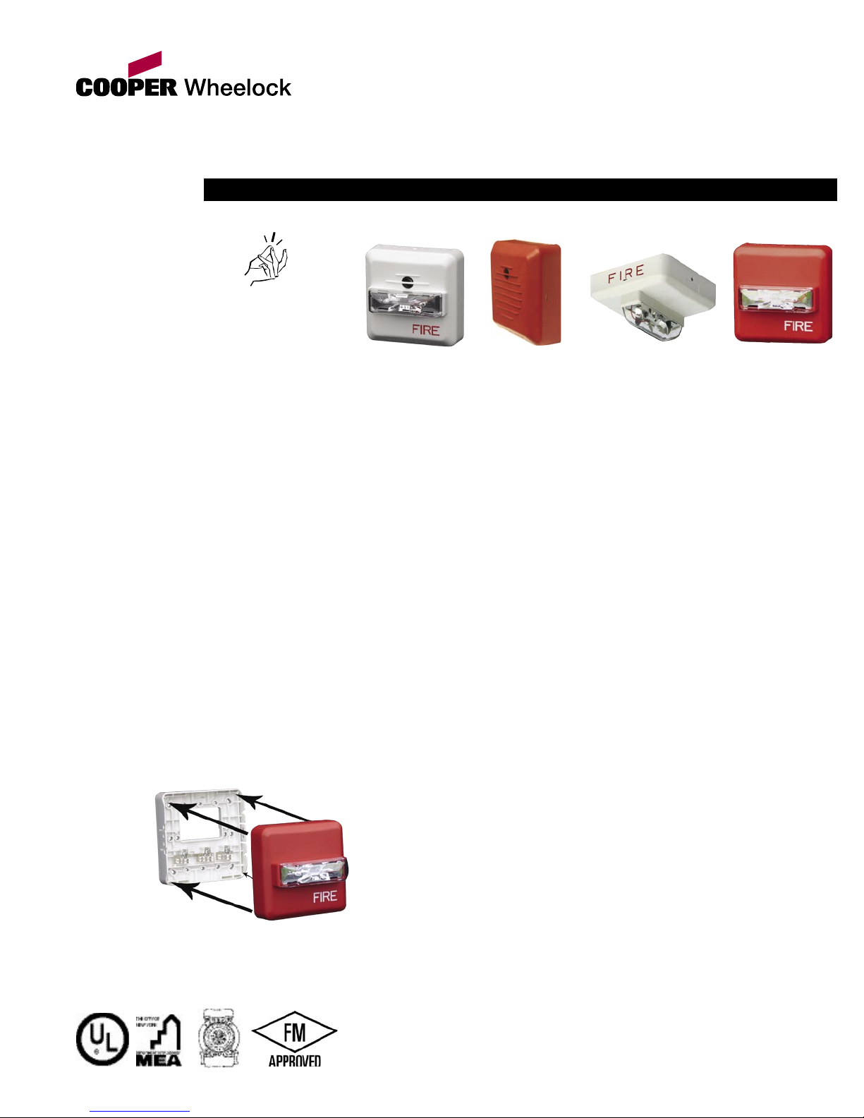
#The ZRS, ZNS and ZNH will mount to single-gang, double-gang, 4” octal, 4” square and 3-1/2” octal back boxes.
Model Number Order
Code
Strobe
Candela
Sync w/ SM,
DSM or
PS-24-8MC
24
VDC
12
VDC
Mounting
Options#
Agency Approvals
UL MEA CSFM FM BFP
ZNS-MCW-FR 0304 15/30/75/110 X X - B, D, E, F X * X * *
ZNS-MCW-FW 0305 15/30/75/110 X X - B, D, E, F X * X * *
ZNS-MCWH-FR 0306 135/185 X X - B, D, E, F X * X * *
ZNS-MCWH-FW 0307 135/185 X X - B, D, E, F X * X * *
ZNH-R 0300 - X X X B, D, E, F X * X * *
ZNH-W 0301 - X X X B, D, E, F X * X * *
ZNS-MCC-FR 0310 15/30/75/95 X X - B, D, E, F X * X * *
ZNS-MCC-FW 0311 15/30/75/95 X X - B, D, E, F X * X * *
ZNS-MCCH-FR 0312 115/177 X X - B, D, E, F X * X * *
ZNS-MCCH-FW 0313 115/177 X X - B, D, E, F X * X * *
ZRS-MCW-FR 4085 15/30/75/110 X X - B, D, E, F X * X * *
ZRS-MCW-FW 0302 15/30/75/110 X X - B, D, E, F X * X * *
ZRS-MCWH-FR 5242 135/185 X X - B, D, E, F X * X * *
ZRS-MCWH-FW 0303 135/185 X X - B, D, E, F X * X * *
ZRS-MCC-FW 0309 15/30/75/95 X X - B, D, E, F X * X * *
ZRS-MCC-FR 0308 15/30/75/95 X X - B, D, E, F X * X * *
ZRS-MCCH-FR 5240 115/177 X X - B, D, E, F X * X * *
ZRS-MCCH-FW 0314 115/177 X X - B, D, E, F X * X * *
ZBASE 5268 Accessory - Includes base, dust cover, mounting screws and installation sheet
ZBB-R 6036 Backbox for indoor suface mounting of all SNAP models
ZBB-W 6045 Backbox for indoor suface mounting of all SNAP models
*Pending
+
-
APPLIANCE
+
-
F
SYNC
+
DUAL SYNC MODULE
A
C
P
S Y N C
+
-
-
A U D IB L E
A U D IB L E
C IR C U IT O U T
+
+
O U T 1
IN 1
M IN U S 1
+
O U T 2
+
IN 2
M IN U S 2
S IG N A L
S IG N A L
C IR C U IT R E T U R N
+
-
+
-
APPLIANCE