Cooper VariSTAR AZE User manual

Cooper PowerSystems
Printed in U.S.A. 1
These instructions do not claim to cover all details or variations in the equipment, procedure, or process described, nor to provide
directions for meeting every contingency during installation, operation, or maintenance. When additional information is desired to
satisfy a problem not covered sufficiently for the user’s purpose, please contact your Cooper Power Systems sales engineer.
CONTENTS
GENERAL . . . . . . . . . . . . . . . . . . . . . . . . . . . . . . . . . . .1
GENERAL APPLICATION RECOMMENDATIONS . . .1
INSPECTION . . . . . . . . . . . . . . . . . . . . . . . . . . . . . . . . .1
IDENTIFICATION . . . . . . . . . . . . . . . . . . . . . . . . . . . . .1
ASSEMBLY . . . . . . . . . . . . . . . . . . . . . . . . . . . . . . . . . .1
Base or Foundation Mounting . . . . . . . . . . . . . . . .2
Bracket or Structure Mounting . . . . . . . . . . . . . . .2
Suspension Mounting . . . . . . . . . . . . . . . . . . . . . . .2
ELECTRICAL CONNECTIONS . . . . . . . . . . . . . . . . . .2
MAINTENANCE . . . . . . . . . . . . . . . . . . . . . . . . . . . . . .4
DIMENSIONS . . . . . . . . . . . . . . . . . . . . . . . . . . . . . . . .5
GENERAL
VariSTAR AZE station class surge arresters incorporate
the latest in metal oxide varistor (MOV) technology.
These arresters are totally gapless and are constructed
of a single series column of MOV disks. The arrester is
designed and tested to the requirements of standard
ANSI/IEEE C62.11 and is available in ratings suitable for
the overvoltage protection of high-voltage systems
through 345 kV.
GENERAL APPLICATION
RECOMMENDATIONS
Cooper Power Systems application engineers are
available to make specific application recommendations.
INSPECTION
The factory takes special precautions to ship arresters
in well designed containers that reduce the possibility of
damage which may occur during transit. Carefully
inspect the porcelain for chips or cracks. In case of
improper handling or shipping damage, immediately file
a claim with the carrier, and promptly notify Cooper
Power Systems or your local representative.
IDENTIFICATION
A nameplate attached to the base casting of each
VariSTAR arrester indicates its catalog number, voltage
rating, maximum continuous operating voltage (MCOV),
rated frequency, pressure-relief current rating, class,
reference to the type test standard, altitude range, serial
number, and year of manufacture.
For multiple unit arresters, a nameplate attached to
the top casting of each unit indicates the catalog number
and serial number of the complete arrester of which the
unit forms a part. The unit nameplate also indicates the
total number of units comprising the complete arrester
and references the position of this unit in the complete
assembly.
ASSEMBLY
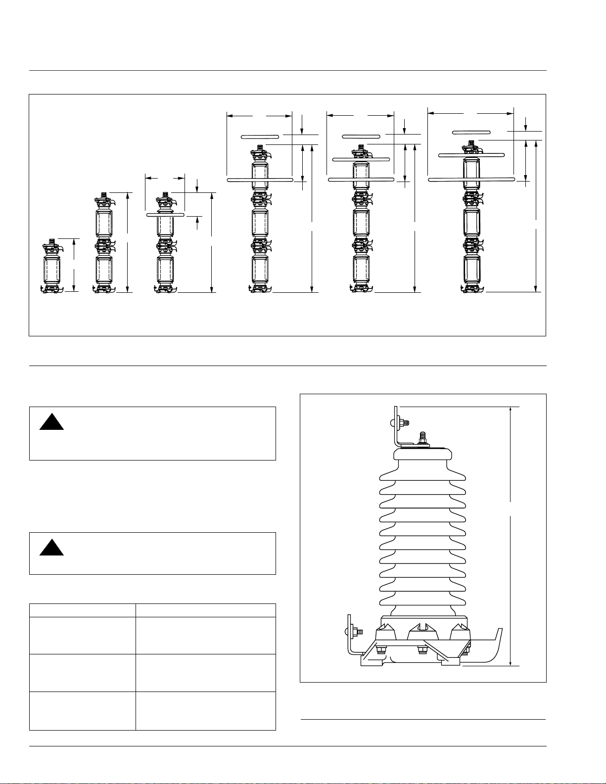
VariSTAR Type AZE arresters rated 3 through 120 kV
are shipped ready for installation. The 132 through 360 kV
standard arresters require the assembly of multiple units
stacked in series. A grading ring is supplied for arresters
rated 172 through 360 kV. Some lower voltage ratings
having extra creepage housings may require multi-units
stacked in series and grading rings. Grading ring
assembly instructions are shown in Figure 6.
Choose a permanent location so that the arresters will
be installed as close as possible (electrically) to the
equipment being protected. Minimum clearance distances
between any line potential surface to an arrester and to
any ground plane are listed in Tables 2 and 3. Figures 1
and 2 show minimum phase-to-ground and minimum
phase-to-phase clearances. See Tables 2 and 3 and
Figures 7 and 8 for standard arrester dimension and
weight information.
Surge Arresters
VariSTAR®Type AZE Station Class Surge Arresters
Installation and Maintenance Instructions S235-87-1
Service Information
August 1997 • New Issue • © 1997 Cooper Power Systems, Inc.
CAUTION: The Cooper Power Systems
VariSTAR Type AZE surge arrester is
designed to be operated in accordance with safe
operating procedures. These instructions are not
intended to supersede or replace proper safety and
operating procedures. Read all instructions before
installing the arrester.
Surge arresters should be installed and serviced only
by personnel familiar with good safety practice and
the handling of high-voltage electrical equipment.
!
CAUTION: Do not install arresters that have
evidence of damage.
!
CAUTION: Always handle surge arresters
carefully. Dropping or jarring an arrester may
cause serious damage to the porcelain and/or
internal parts and may cause catastrophic failure
upon energization.
!
CAUTION: The values shown in Tables 2 and
3 are the minimum clearances recommended
by Cooper Power Systems. These minimum clear-
ances may be increased to meet local or system
requirements for spacing of energized equipment.
Safe operating practices must always be followed.
!

Base or Foundation Mounting
Pier footings should extend below the frost line. Elevate
the foundation sufficiently above the ground line for
personnel safety and to prevent contamination from
ground splash, drifting snow, flood water, or other
contaminating conditions. If the top of the foundation is
not level, shims will be required for leveling. Layout
mounting dimensions for the foundation are shown in
Figure 3.
Bracket or Structure Mounting
When bolting arresters directly to structures, or
mounting brackets, make the assembly rigid enough
to prevent mechanical failure.
Suspension Mounting
AZE arresters rated through 168 kV can be suspension-
mounted. Either the top or bottom of suspension-
mounted arresters can be connected to the line as long
as the sheds on the porcelain housings are not inverted.
For additional information regarding suspension mounting,
contact your Cooper Power Systems factory
representatives.
Figure 1.
Three-phase triangular mounting.
Note: Refer to Table 1 for Dimension “B”.
2
CAUTION: Make electrical connections so
that no mechanical stress is applied to the
arrester.
!
CAUTION: The vent port in the base must
be directed away from equipment to prevent
ionized gases from damaging adjacent equipment in
the unlikely event of arrester failure.
!
CAUTION: To prevent strains on the
arrester when suspension-mounting,
suspend it freely. Always make flexible connections
to line and earth terminals.
!
ELECTRICAL CONNECTIONS
Install the arrester as close as possible (electrically) to
the apparatus being protected. Line and ground
connections must be short and direct. Make the ground
connection to a solid, effective and permanent low-
resistance ground.
NOTE: Equipment protection will be improved by
interconnecting the arrester ground connections with
the transformer tank and system neutral whenever
possible.
The standard line and ground terminals (Figures 4
and 5) include connector clamps that accommodate up
to 0.75 inch stranded copper or aluminum conductor.
The line and ground terminals allow the connector
clamp to be positioned for vertical or horizontal
conductor takeoff; in addition, it accommodates NEMA
standard two or four-hole connectors.
Figure 2.
Three-phase in-line mounting.
Note: Refer to Table 1 for Dimensions “B” and “C”.
VariSTAR®Type AZE Station Class Surge Arresters
0.5 “B”
VENT PORT
0.866 “B”
“B”
“B”
“B”
“C”
“C”
“B” “B”
VENT PORT
Figure 3.
Base mounting details.
*To develop rated cantilever strength use 10 inch bolt circle
mounting diameter and 0.5 inch hardened bolts and flat washers.
120°
60°
(3) 0.625" x 1.27"
(1.6 x 3.2 cm) LG. MTG.
SLOTS (120°APART)
8.75"-10" (22.2 – 25.4 cm) DIA.
BOLT CIRCLE*
THICKNESS OF
MOUNTING FEET IS 0.875" (2.2 cm)

3
Figure 4.
Line terminal cap (metal-top design).
3.0”
(7.62 cm)
0.75”
(1.90 cm)
1.75”
(4.44 cm)
1.37”
(3.49 cm)
3.75”
(9.52 cm)
CLAMP
TYPICAL
OF TWO
0.44” (1.11 cm)
DIA. HOLES ON
1.75” (4.44 cm)
CENTERS
0.56” (1.43 cm)
DIA. HOLES ON
1.75” (4.44 cm)
CENTERS
S235-87-1
Figure 5.
Ground terminal (also line terminal of cubicle-mount
designs).
3.00”
(7.62 cm)
0.44” (1.11 cm) SQ. HOLES
ON 1.37” (3.49 cm)
CENTERS
CLAMP
TYPICAL
OF TWO
3.75”
(9.52 cm)
Figure 6.
Grading ring assembly.
Note: Arresters with extra creepage housings may require grading rings in different voltage ratings.
ARRESTER RATINGS =172-240 kV ARRESTER RATINGS = 258-288 kV ARRESTER RATINGS = 294-360 kV
PLACE THE (3) GRADING RING MOUNTING TABS UNDER LINE TERMINAL CAP.
MOUNTING TAB
MOUNTING TAB
MOUNTING TAB
0.56” (1.43 cm) DIA. HOLES
ON 1.75” (4.44 cm)
CENTERS

4
VariSTAR®Type AZE Station Class Surge Arresters
MAINTENANCE
WARNING: Before working on arresters,
disconnect all line leads. Consider any part
of an arrester dangerous when connected to the line,
including a base not solidly grounded.
!
VariSTAR Type AZE arresters require no special
maintenance under normal conditions. If the arrester is
installed in an area of severe contamination, keep the
arrester housing clean by washing periodically. Keep
line and ground connections tight.
WARNING: Arresters can be washed while
energized provided standard live washing
procedures are followed.
!
“A”
“A”“A”
“A”
“A”
“A”
30”
(77 cm)
24”
(60 cm)
24”
(60 cm)
16”*
(40 cm)
3-120 kV 132-168 kV 172-240 kV 258-288 kV 294-312 kV 330-360 kV
Figure 7.
Dimensions of VariSTAR metal-top Type AZE surge arresters.
Note: Refer to Table 2 for Dimension “A”.
7”
(18 cm) 7”
(18 cm)
7”
(18 cm)
26”
(66 cm)
DIA.
42”
(107 cm) DIA.
42”
(107 cm) DIA.
55”
(140 cm) DIA.
*FOR 172 kV ARRESTER
DIMENSION IS 12" (30 cm)
TABLE 1
Cantilever Strength of Metal-Top AZE Surge Arresters
AZE Type Cantilever Strength (in-lbs)*
AZES
Arrester Rating
3-240 kV 90,000
258-360 kV 120,000
AZEH
Arrester Rating
3-108 kV 90,000
120-240 kV 120,000
AZEX
Arrester Rating
3-48 kV 90,000
54-108 kV 120,000
Figure 8.
Dimensional drawing of VariSTAR cubicle-mount type
AZE surge arrester.
Note: Refer to Table 3 for dimension “A”.
* Maximum working load should not exceed 40% of these values.
“A”

5
S235-87-1
TABLE 2
Dimensional Information and Weights for Type AZE Metal-Top Surge Arresters in Standard Housings
Figures 1 & 2 Dim. “B” Figure 2 Dim. “C”
Minimum Clearance Minimum Clearance Weight
Phase-to-Phase (in.) Phase-to-Ground (in.) (lbs.)
Arrester Arrester Figure 7
Rating MCOV Dim. “A”
(kV, rms) (kV, rms) (in.) AZES AZEH AZEX AZES AZEH AZEX AZES AZEH AZEX
3 2.55 18.6 12 12 12 6 6 6 42 42 42
6 5.10 18.6 12 12 12 7 7 6 42 43 44
9 7.65 18.6 13 13 12 7 7 7 43 44 45
10 8.40 21.1 13 13 13 7 7 7 48 49 50
12 10.2 21.1 14 13 13 8 8 7 49 50 52
15 12.7 21.1 14 14 14 9 8 8 49 51 53
18 15.3 24.8 15 15 14 10 9 9 56 58 63
21 17.0 24.8 16 16 15 11 10 9 57 59 65
24 19.5 24.8 16 16 15 11 10 9 58 60 66
27 22.0 28.6 17 17 16 12 11 10 65 68 77
30 24.4 28.6 18 17 17 13 12 11 65 68 77
33 27.5 28.6 20 19 18 14 13 12 66 69 79
36 29.0 28.6 20 19 18 14 13 13 66 70 80
39 31.5 33.6 21 20 19 15 14 13 77 81 95
42 34.0 33.6 22 21 19 16 15 14 78 82 96
45 36.5 33.6 23 21 20 17 16 14 78 83 98
48 39.0 33.6 24 22 21 18 17 15 78 83 98
54 42.0 36.6 25 23 22 20 18 16 86 91 114
60 48.0 36.6 28 25 24 22 20 18 87 93 117
66 53.0 39.4 30 27 25 24 21 20 96 102 130
72 57.0 39.4 31 28 27 26 23 21 97 104 131
78 62.0 48.0 33 30 28 28 25 22 116 123 156
84 68.0 48.0 36 32 30 30 27 24 118 125 159
90 70.0 48.0 36 33 31 31 27 25 118 126 159
96 76.0 48.0 39 35 32 33 29 27 119 128 162
108 84.0 56.5 42 38 35 36 32 29 161 170 206
120 98.0 56.5 43 39 – 37 34 – 175 213 –
132 106 71.5 46 42 – 40 36 – 191 243 –
138 111 71.5 47 43 – 42 38 – 193 246 –
144 115 74.4 49 45 – 43 39 – 202 258 –
162 130 80.1 54 49 – 48 44 – 217 277 –
168 131 82.9 54 50 – 48 44 – 225 287 –
172 140 83.2 72 67 – 59 54 – 237 300 –
180 144 88.9 73 68 – 60 55 – 270 332 –
192 152 88.9 76 71 – 63 58 – 273 336 –
198 160 91.8 79 73 – 66 60 – 283 350 –
204 165 100.3 81 75 – 68 62 – 303 374 –
216 174 100.3 84 78 – 71 65 – 306 378 –
228 182 108.9 86 80 – 73 67 – 348 422 –
240 190 108.9 89 83 – 76 70 – 351 426 –
258 209 123.9 105 – – 84 – – 472 – –
264 212 123.9 106 – – 85 – – 473 – –
276 220 132.5 108 – – 87 – – 499 – –
288 230 132.5 111 – – 90 – – 503 – –
294 235 135.3 113 – – 92 – – 524 – –
300 239 135.3 114 – – 93 – – 526 – –
312 245 141.0 116 – – 95 – – 558 – –
330 267 152.4 136 – – 108 – – 605 – –
336 269 152.4 136 – – 109 – – 606 – –
360 289 161.0 143 – – 115 – – 655 – –
Note: The cantilever strength of metal-top AZE Surge Arresters are listed in Table 1.

VariSTAR®Type AZE Station Class Surge Arresters
6
Cooper PowerSystems
Quality from
Cooper Industries
Printed on Recycled Paper
P.O. Box 1640, Waukesha, WI 53187
www.cooperpower.com
VariSTAR®is a registered trademark of Cooper Industries, Inc.
TABLE 3
Dimensional Information and Weights for Type AZE Cubicle-Mount Surge Arresters in Standard Housings
Figures 1 & 2 Dim. “B” Figure 2 Dim. “C”
Minimum Clearance Minimum Clearance Weight
Phase-to-Phase (in.) Phase-to-Ground (in.) (lbs.)
Arrester Arrester Figure 8
Rating MCOV Dim. “A”
(kV, rms) (kV, rms) (in.) AZES AZEH AZES AZEH AZES AZEH
3 2.55 13.4 8 8 4 4 23 23
6 5.10 13.4 8 8 5 5 24 24
9 7.65 13.4 8 8 5 5 24 25
10 8.40 15.9 8 8 5 5 29 30
12 10.2 15.9 9 9 6 5 30 31
15 12.7 15.9 10 10 7 6 30 32
18 15.3 20.2 11 10 8 7 38 39
21 17.0 20.2 12 11 8 8 38 40
24 19.5 20.2 12 11 9 8 39 41
27 22.0 23.4 13 12 10 9 47 49
30 24.4 23.4 14 13 11 10 47 49
33 27.5 23.4 15 14 12 11 47 50
36 29.0 23.4 16 15 12 11 48 51
39 31.5 28.4 17 16 13 12 59 63
42 34.0 28.4 18 16 14 13 60 64
45 36.9 28.4 19 17 15 14 60 65
48 39.0 28.4 20 18 16 15 60 65
Note: Cooper Power Systems recommends that a line terminal load limit of 100 pounds not be exceeded on cubicle mount designs. Excessive
loading could lead to a shortened arrester life.
MI
8/97 3M
Cooper Power Systems
ISO 9001-1994 Cert. #003945
Olean, N.Y.
Table of contents
Other Cooper Industrial Electrical manuals
Popular Industrial Electrical manuals by other brands

Eaton
Eaton XTCE080F F47 Series Instruction leaflet

Murata
Murata GRM1885C2A160JA01 Series Reference sheet

Murata
Murata GRT155R60J225KE01 Series Reference sheet

Murata
Murata GRM1885C1E821JA01 Series Reference sheet

Softing
Softing FG-200 HSE/FF user manual

Siemens
Siemens 3VT9500-1U.00 operating instructions

ELTEX
ELTEX R23ATR Series operating instructions

Murata
Murata GRM3195C1H103JA01 Series Reference sheet

Greenheck
Greenheck AMD-42-TD Installation, operation and maintenance manual

DURAG
DURAG D-TB 100 Series operating manual

Bredenoord
Bredenoord ESaver III Operation manual

Graco
Graco Series A Repair instructions