manuals.online logo
Brands
  1. Home
  2. •
  3. Brands
  4. •
  5. Copland
  6. •
  7. Music Equipment
  8. •
  9. Copland DRC205 User manual

Copland DRC205 User manual

Popular Music Equipment manuals by other brands

Aguilar CHORUSAURUS user guide

Aguilar

Aguilar CHORUSAURUS user guide

Fishman NEO-D user guide

Fishman

Fishman NEO-D user guide

HEXDEVICES Tama 12 user manual

HEXDEVICES

HEXDEVICES Tama 12 user manual

Mesa/Boogie Flux-drive owner's manual

Mesa/Boogie

Mesa/Boogie Flux-drive owner's manual

DOLFINOS The CARBON Edition user manual

DOLFINOS

DOLFINOS The CARBON Edition user manual

DAPAudio IPS-PT user guide

DAPAudio

DAPAudio IPS-PT user guide

Dynacord DPM 8016 owner's manual

Dynacord

Dynacord DPM 8016 owner's manual

Moen GEC8 Live owner's manual

Moen

Moen GEC8 Live owner's manual

Fender 1 brochure

Fender

Fender 1 brochure

Yamaha MLC-16 operating manual

Yamaha

Yamaha MLC-16 operating manual

Sonuscore TIME TEXTURES manual

Sonuscore

Sonuscore TIME TEXTURES manual

flight of harmony V'Amp user guide

flight of harmony

flight of harmony V'Amp user guide

NANO PERFORMANCE MIXER quick guide

NANO

NANO PERFORMANCE MIXER quick guide

BHI NEIM 1031 MKII user guide

BHI

BHI NEIM 1031 MKII user guide

Befaco KICKALL user manual

Befaco

Befaco KICKALL user manual

Paia 9720 Assembly and using manual

Paia

Paia 9720 Assembly and using manual

limex ALPIN MASTER 128 user manual

limex

limex ALPIN MASTER 128 user manual

nord Electro 3 user manual

nord

nord Electro 3 user manual

manuals.online logo
manuals.online logoBrands
  • About & Mission
  • Contact us
  • Privacy Policy
  • Terms and Conditions

Copyright 2025 Manuals.Online. All Rights Reserved.

1




















2

We would like to take this opportunity to thank you for selecting the DRC205 Room
Compensation.
We at Copland wish you many enjoyable hours in the company of fine music.
Please read this owners manual before operating the equipment.
The DRC205 is a highly complicated device that must be operated according to our
recommendations to secure safe and optimum performance.

1 pcs. Copland DRC205
1 pcs. AC-cord
1 pcs. Measuring Microphone (DRC205 calibrated)
1 pcs. Microphone Cable
1 pcs. Windows compatible CD-ROM
1 pcs. User Manual
 !"
Various regulation agencies require us to bring the following information to your attention.
Please read carefully.
# ""To prevent fire or shock hazard, do not expose this unit to rain or moisture.
 Check that your supply voltage is the same as indicated on the DRC205.
Do not connect the AC Power to the mains sockets if the voltage of the mains
is not as printed just below the AC Power inlet! This may cause fire hazard,
damage to equipment or personal hazard!
 Dangerous voltage inside. Do not open the cabinet. There are no user
serviceable parts inside. Repairs should be carried out by qualified service
personnel only.
 Ensure that no objects or fluids pass through openings in the chassis. If liquid is
spilt into the DRC205, disconnect from the mains and consult a qualified service
technician.

Open the carton and remove the DRC205 from its plastic bag.
The accessories are placed in the bottom of the packaging materials.
Before placing the unit in your home read this carefully.
Place the DRC205 on a stable platform in a normally dry environment. Do not subject the
DRC205 to high mechanical vibration.
By normal operation the DRC205 is operated from the front panel. However, during set-up
access to the rear-panel can be necessary.
$ %& When AC-power is applied for the first time or if AC-power has been
disconnected: Please wait for minimum 10 seconds before operating the DRC205, to allow
all power supplies and microcontrollers to become operational.
3

'('')'
To be acquainted with the DRC205, please read the following descriptions of the connections
on the unit and view the positions of connections below.
''






7 6 6 5 5 4 3 2 1






* '& The AC power cord is plugged here.
The correct mains operating voltage is printed just below the mains inlet.

 The DRC205 is supplied in either 110/120 Volt 50/60 Hz versions,
or 220/240 Volt 50/60 versions.
Only use a version compliant with your wall outlet voltage!
 Do not connect the AC Power to the mains sockets if the voltage of the mains is
not as printed just below the AC Power inlet! This may cause fire hazard, damage
to equipment or personal hazard!
The DRC205 has very low power consumption and does thus not feature a power
switch! It is recommended to leave the unit turned on.
4

$ %''& IBM PC compatible USB port interface connector for
communication between a Windows 98/ME/2000/XP compatible PC/Computer
and the DRC205.
The connection can be used during set-up and calibration – or by advanced use of the
DRC205.
Connecting a PC/Computer with to the DRC205 is not required.
The Copland DRC205 can be operated as stand-alone unit without any external
usage of a PC/computer.
Advanced and professional users may prefer to set-up and calibrate the unit and the audio
system by help of an external Windows PC/computer. This increases the user flexibility of the
unit, but also makes set-up and calibration more complex.
If external PC/computer assisted operation is desired, then the [Computer] connection is only
necessary during set-up and calibration of the unit and the audio system.
 Reduce the volume control on the amplifier (or pre-amplifier) during connection or
disconnection of the PC/computer! This provides optimum protection to our
loudspeakers.
 The front-panel keys are DEACTIVATED when an external Windows compatible
PC/Computer controls the unit!
Connect the Windows PC/computers USB port to the [Computer] connection of the DRC205
before set-up and calibration of the unit and your audio system.
 The computer does not need to be connected to the unit during normal playback
operation. However, the Windows compatible PC/computer can be used to control
the DRC205 if desired. (This is an advantage during manual set-up of P1 and P2
user programmes.)
Contact your dealer in case your PC/Computer is not Windows 98/ME/2000/XP compatible
and ask for potential updates of the DRC205 unit for support of non-compatible computers. (At
the closing of hereby User Manual only Windows compatible PC/Computers are supported by
the Copland DRC205.)
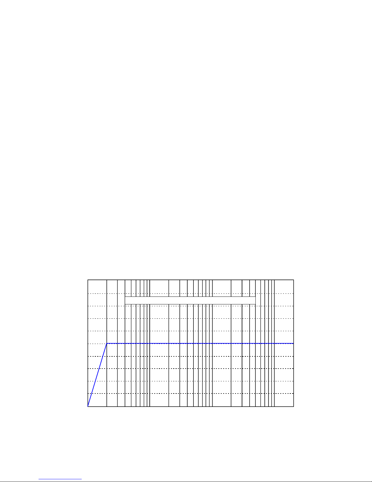
+,)-''& The [High-Pass] selector corresponds to the Subsonic protection
filter indicators on the front panel.
The [High-Pass] selector is a 10-position rotary switch that must be preset according to the
audio system and loudspeakers used with the DRC205.
 Important note: The [High-Pass] selector is ONLY active during set-up, calibration,
test and measurements! The setting has no negative impact upon the sonic
performance during playback. The function is designed only to protect your
loudspeakers during set-up, calibration, test and measurement!
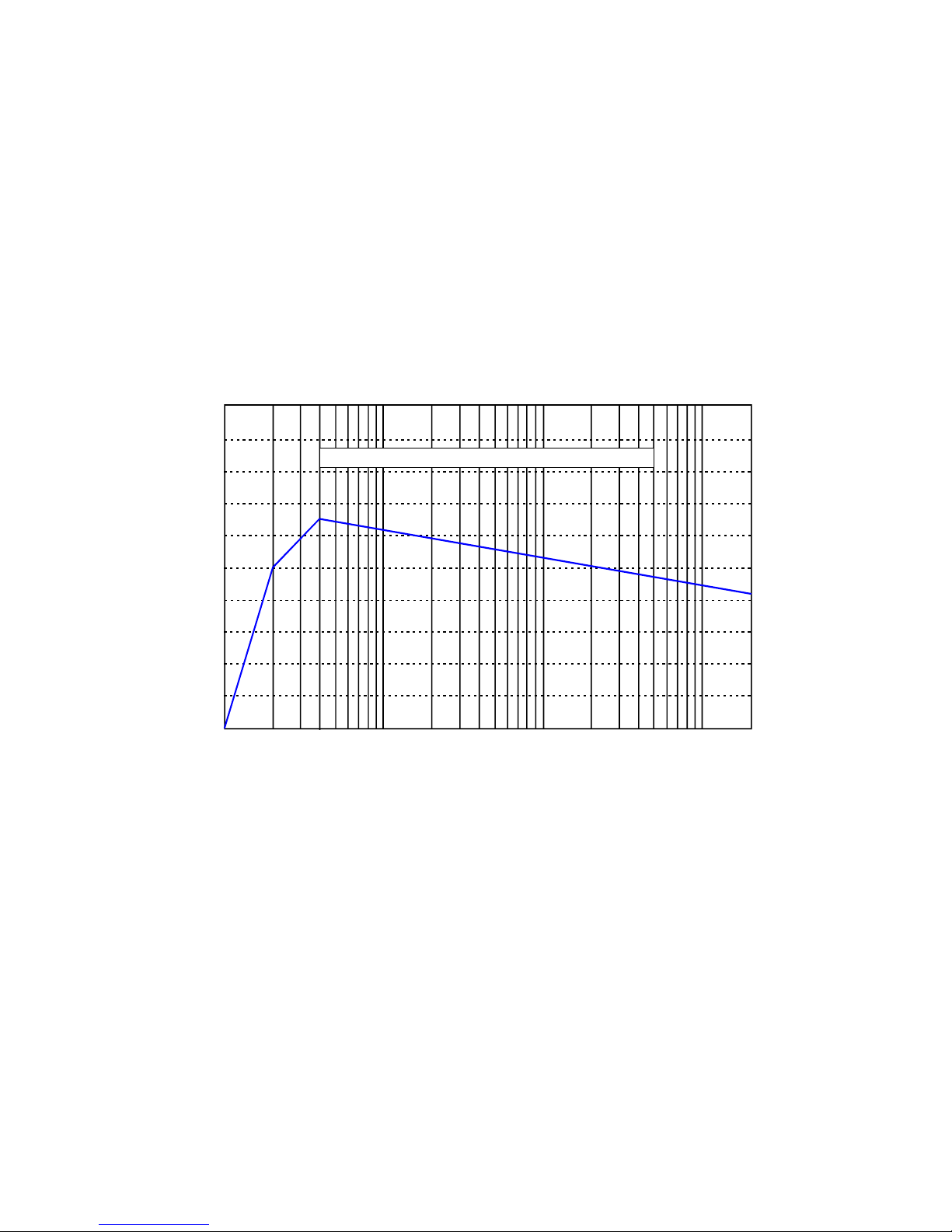
[] sets the high-pass filter (subsonic protection filter) at a cut-off of 16 Hz.
[Position 1] should ONLY be used in audio systems featuring large and rugged loudspeakers
capable of handling subsonic frequencies at FULL power!
It is recommended that [Position 1] is only used in audio systems featuring rugged 12”-15”
woofers or similar high-performance/high-power subwoofers and for laboratory measurement.
5
[] sets the high-pass filter (subsonic protection filter) at a cut-off of 20 Hz.
[Position 2] should ONLY be used in audio systems featuring larger and rugged loudspeakers
capable of handling subsonic/bass frequencies at FULL power!
It is recommended that [Position 2] is only used in audio systems featuring rugged 8”-10”
woofers or similar high-performance/high-power subwoofers!
[+] sets the high-pass filter (subsonic protection filter) at a cut-off of 32 Hz.
[Position 3] should be used in audio systems featuring high-quality floor standing fairly rugged
loudspeakers capable of handling bass frequencies at high power.
It is recommend that [Position 3] is used in audio systems featuring rugged 6”-8” woofers or
similar high-performance/high-power subwoofers!
[.] sets the high-pass filter (subsonic protection filter) at a cut-off of 40 Hz.
[Position 4] should be used in audio systems featuring high-quality bookshelf or general-
purpose loudspeakers!
Copland recommends that [Position 4] is used in audio systems featuring small or general-
purpose woofers or similar standard subwoofers!
 Important note: The [High-Pass] selector is set DEFAULT at [Position 3] !
 Important note: Do NOT change the default setting to a lower value, unless you
are sure that your loudspeaker as minimum fulfils our recommendations!
 Important note: Copland cannot be made liable for any damage to external
equipment used with the unit.
./ %)'%& 3.5mm Jack connector for the measuring microphone.
The Microphone connection is only used during set-up and calibration of the unit and the audio
system.
Connect the measuring microphone to the Microphone connection before set-up and
calibration of the unit and your audio system.
Disconnect the measuring microphone from the unit after set-up and calibration is done!
 The microphone do not need to be connected to the unit during playback
operation. The microphone has no operational functions during playback.
 Reduce the volume control on the amplifier (or pre-amplifier) during connection or
disconnection of the microphone! This provides optimum protection to our
loudspeakers.
 Important note: The DRC205 is calibrated to the featured microphone!
The microphone are calibrated for optimum performance.
 Important note: Do NOT connect an other microphone to the unit without running a
microphone calibration!
 Important note: Do NOT connect any third-party microphone to the unit! The
microphone calibration will NOT work with third-party microphones!
6
%& Read below.
0%& Read below.
The analog inputs and outputs of DRC205 supports cables with RCA connectors.
Connect the DRC205 to the TAPE MONITOR facility of your amplifier.
This will provide optimum flexibility in regard to operation of the unit.
Provided that your amplifier do not have a TAPE MONITOR connection, then you can connect
the DRC205 between your primary line signal source (e.g. a CD-Player) and your amplifier.
 Highly recommended: Do not install the DRC205 between a pre-amplifier and power-
amplifier (unless this is your only option for connecting the unit). The performance of a digital
processing unit like the DRC205 will be degraded by connection between pre-amplifiers and
power-amplifiers. Signal/Noise ratio will be impaired. Dynamic range will be impaired.
%&Connect the DRC205 [Inputs] to the [Outputs] of the TAPE MONITOR connection
of your amplifier.
Alternative operation : If no TAPE MONITOR is available: Connect the DRC205 inputs to the
outputs of a line signal source (e.g. a CD-Player).
!%&Connect the DRC205 [Outputs] to the [Inputs] of the TAPE MONITOR connection
of your amplifier.
Alternative operation : If no TAPE MONITOR is available: Connect the DRC205 outputs to a
line signal input of the amplifier (e.g. a CD-Player input ).
To minimise the introduction of hum and noise the shielded cables should run parallel to each
other or loosely twisted together. Locate the cables away from speaker leads and AC power
cords.
1'"$ 2'& Serial number information is important for future software upgrades!
 Important note: Do NOT remove or damage the serial number. Missing serial
number may result in no possibility to perform future firmware upgrades of the unit!


7
3'
The following description of the front panel may help you locating the operation features of
the unit.
Note that all functions are disabled on the front panel when the DRC205 is operated via a
Windows compatible PC/Computer!
1 2 3 4
'''4&By pressing this button, the unit will be switched between the 6 (six) different
playback programmes. 
Each time the key is pressed the programme is switched cyclically between A1, A2, A3, A4, P1
and P2 programmes. Detailed information about the programmes can be found on following
sides of this user guide.
 The [Select] key changes the tonal characteristic of the calibrated audio system
according to the programmes A1, A2, A3, A4, P1 and P2.
 The [Select] key may be pressed upon desire during playback.
 The [Select] key should not be activated during set-up and calibration! The [Select]
key is only for playback operation.
42$ '& LED indicator lamps will light when [Select] of A1, A2, A3,
A4, P1 or P2 is selected for playback mode.
Detailed information about the playback modes can be found on the following sides.

+2%'5'&LED will light for the selected cut-off frequency for
the subsonic protection filters (controlled by the [High-Pass] key on the rear-panel of the unit).
The subsonic protection filter is only active during set-up and calibration of the unit.
See more details about the recommended settings of [High-Pass] key on rear-panel of the unit
below!
.'%'4& By pressing this button continuously for at least 3 (three) seconds, the
automatic set-up and calibration function of the unit is activated.
 Do not press the [Setup] key during normal playback !
8
 In case the [Setup] key is pressed indivertible, then a safety feature in the unit
avoid that test- and measurements is started unless the button is continuously
pressed for more than 3 (three) seconds.
42$ '6((+(.7
Playback modes A1-A4 are predefined sound characteristics.
The playback modes determine the tonal balance of the compensated audio system.
& Pre-programmed playback mode A1 changes the overall sound characteristics to the
below frequency response. The basic characteristic of A1 is resulting in a flat linear frequency
response similar to the classic technical reference.
10Hz 50Hz 100Hz 500Hz 1kHz 5kHz 10kHz 20kHz
0dB
-4dB
-8dB
-12dB
-16dB
+ 4dB
+ 8dB
+ 12dB
+ 16dB
+ 20dB
-20dB
TARGETCURVE- LINEARRESPONSE (FLATRESPONSE)
9
& Pre-programmed playback mode A2 changes the overall sound characteristics to the
below frequency response. The basic characteristics of A2 is that the acoustics energy in the
bass range which by nature is boosted by room reflections is re-created, however without the
room acoustics problems negative impact. To avoid the sound of the audio system being too
bright (and hereby “technical” rather than “musical”) a slight attenuation in higher mid-range
and lower high-range is applied. Controlled roll-off in the upper octave is applied.
 A2 is advantageous to a very wide range of audio systems and is recommended
for users with personal preferences of “musical” sound characteristic rather than
“technical” sound characteristics.
10Hz 50Hz 100Hz 500Hz 1kHz 5kHz 10kHz 20kHz
0dB
-4dB
-8dB
-12dB
-16dB
+ 4dB
+ 8dB
+ 12dB
+ 16dB
+ 20dB
-20dB
TARGETCURVE- BRITISH BROADCASTING COMPANY
The A2 pre-programmed playback mode creates a sound characteristic very similar to the
preference of British Broadcast Company (BBC) in the higher frequency ranges and re-creates
a modest bass boost that improves the typical performance of most high-fidelity loudspeakers.
 A2 may not be recommended for large loudspeakers capable of generating large
energy levels in the lowest octaves. A2 may not be recommended for very small
loudspeakers incapable of reproducing the lowest octaves with realistic energy
level (unless the loudspeakers limitations in regard to maximum sound pressure
level is fully respected).
10
+& Pre-programmed playback mode A3 changes the overall sound characteristics to the
below frequency response. The basic characteristic of A3 is resulting in a linear frequency
response with a modest tilt. The tilt secures that the tonal balance after compensation is
natural. Many loudspeakers generate insufficient energy in the lower octaves as well as in the
important fundamental frequency range (Higher bass/lower mid-range), and at the same time
generate too much energy in the highest octaves. A3 creates a natural linear response after
compensation.
 A3 is advantageous to a very wide range of audio systems and is recommended
for users with personal preferences of “musical” sound characteristic rather than
“technical” sound characteristics. A3 suits most classic designed high-fidelity
loudspeakers.
10Hz 50Hz 100Hz 500Hz 1kHz 5kHz 10kHz 20kHz
0dB
-4dB
-8dB
-12dB
-16dB
+ 4dB
+ 8dB
+ 12dB
+ 16dB
+ 20dB
-20dB
TARGETCURVE- CINEMA-STYLELINEARRESPONSE
 A3 is especially advantageous to smaller loudspeakers – e.g. bookshelf
loudspeakers and medium size loudspeakers on stands.
 A3 is furthermore advantageous in audio systems being used in movie systems.
 A3 may not be recommended for large loudspeakers capable of generating large
energy levels in the lowest octaves. A3 may not be recommended for very small
loudspeakers incapable of reproducing the lowest octaves with realistic energy
level (unless the loudspeakers limitations in regard to maximum sound pressure
level is fully respected).
.& Pre-programmed playback mode A4 is as default set as talk-through (by-pass /
no compensation).