Technics SX-PR53 User manual

ORDERNO. EMID0006012C0
A5
Digital Ensemble
SX-PR53 / SX-PR53M
(P)U.S.A.
(PC) Canada
(PY)Mexico
(EX)Norway, Sweden, Denmark, Finland, Spain, Portugal, South
Africa
(EF)France
(EZ)Germany
(EG)Switzerland, Italy, Austria, Holland, Belgium
(EB) theUnitedKingdom
(GN) Australia, NewZealand
(XS)Malaysia, Singapore
(XT)Taiwan
(X)Columbia, Panama, Chile, Brazil, Philippines, Venezuela, Ecuador
(XA)Argentina
(XD) Saudi Arabia, Hong Kong, Kuwait
SPECIFICATIONS

SPECIFICATIONS
KEYBOARD 88 KEYS
SOUND GENERATOR PCM
MAXIMUMNUMBEROF NOTES
PRODUCEDSIMULTANEOUSLY 32 NOTES
PLAYSTYLE PIANO MODE, KEYBOARD
SPLIT, AUTO PLAYCHORD
SOUNDS NUMBEROF SOUNDS:
252 SOUNDS+12 DRUMKITS
PIANO:
GRAND, UPRIGHT, ELECTRIC,
MODERN
SOUND GROUP:
PIANO &EPIANO, GUITAR,
STRINGS, VOCAL, BRASS,
FLUTE, BASS, DRUMKITS,
MALLET &ORCH PERC,
WORLDPERC, ORGAN&
ACCORDION, SAX, REED,
SYNTHLEAD, SYNTHPAD,
PERC &EFFECT, MIXTURES
CONDUCTOR RIGHT 1, RIGHT 2, LEFT
SELECT
PEDAL SUSTAIN, SOFT/SOSTENUTO
DIGITAL EFFECT supported
CHORUS supported
DIGITAL REVERB supported
TRANSPOSE G-C-F#
RHYTHMS 128 RHYTHMS ×4VARIATIONS
GROUP:
8&16 BEAT, ROCK, SOUL &
DISCO, BIG BAND &SWING,
COUNTRY&WESTERN, SHOW
TIME, LATIN, BALLAND, FUNK
&FUSION,GOSPEL &BLUES,
JAZZ COMBO, BALL ROOM,
MARCH &WALTZ, WORLD
METRONOME Supported
CONTROLS MAINVOLUME, RHYTHM
VOLUME, BALANCE/MUTE,
START/STOP, INTRO &ENDING
1, INTORO &ENDING 2, FILL IN
1, FILL IN2, COUNT INTRO,
SYNCHRO START, TEMPO, TAP
TEMPO, SPLIT POINT,
EXECUTE,SOUND SELECT,
RHYTHMSELECT
AUTO PLAYCHORD BASIC, ADVANCED1,
ADVANCED2, PIANIST, ON
BASS, MUSICSTYLE
ARRANGER
ONETOUCH PLAY Supported (ONETOUCH PLAY/
MUSICATYLESELECT)
PIANO STYLIST Supported

TECHNI-CHORD Supported
PANEL MEMORY 1-5, SET
SEQUENCER 16 TRACKS
RESOLUTION:96 PULSES PER
QUARTER-NOTE
STRAGECAPACITY:
APPROX.30000 NOTES (10
SONGSMAX.)
INPUT MODES:EASYRECORD,
REALTIME RECORD, STEP
RECORD (CHORD, RHYTHM)
FUNCTIONS:TRACK ASSIGN,
EDIT,SONG SELECT/NAME,
MEDLEY
COMPOSER 5PARTS:BASS, ACCOMP 1,
ACCOMP 2, ACCOMP 3,
DRUMS
STRAGECAPACITY:
APPROX.10000 NOTES
INPUT MODES:REALTIME
RECORD
FUNCTIONS:COMPOSER
CHORD MAP, MODESELECT,
PATTERN COPY, LOADSINGLE
COMPOSERPATTERN
MEMORY: 3BANKS×10
(VARIATION1-4, INTRO 1, 2,
FILLIN1, 2, ENDING 1,2)
MEMORY&CONTROL INITIAL, DISKLOAD, DISK
SAVE, DIRECT PLAY, MEDLEY,
PEDAL SETTING, FLOPPYDISK
FORMAT, CONTRAST
SOUND SETTING PART SETTING, TOUCH &
TUNE, KEYSCALING, LEFT
HOLD, TECHNI-CHORD,
REVERB, CHORUS
MIDI CHANNEL, CONTROL
MESSAGE, PART SETTING,
REALTIME MESSAGE,
COMMONSET, MIDI PRESETS,
IN/OUT SET, GMMODE
EXTERNAL MEMORY BUILT-IN3.5inch FLOPPY
DISKDRIVE FOR2HD (1.44
MB), 2DD (720 KB)
DISPLAY LCD
PAGE, BALANCE, EXIT,
DISPLAYHOLD, OTHERPARTS/
TRACKS
DEMO Supported
TERMINALS PHONES, LINEOUT (R/R+L,L),
AUXIN(R/R+L,L), MIDI (IN,
OUT), PEDAL IN
OUTPUT 40 W×2
SPEAKERS 14 cm ×2

POWERREQUIREMENT 110 W
AC120/220/230-240V50/60 Hz
AC120V60 Hz(NORTH
AMERICAAND MEXICO)
AC230-240 50/60 Hz(EUROPE,
AUSTRALIAAND NEW
ZEALAND)
DIMENSIONS(W×H×D) SX-PR53:
139.7cm ×103.6cm ×56.9cm
(55”×40-25/32”x22-13/32”)
SX-PR53M:
139.7cm ×104.2cm ×56.9cm
(55”×41-1/32”x22-13/32”)
NET WEIGHT SX-PR53:
51 kg (112.4lbs.)
SX-PR53M:
52 kg (114.6lbs.)
ACCESSORIES ACCORD, MUSICSTAND
2000 Matsushita ElectricIndustrial Co., Ltd. All rights reserved.
Unauthorizedcopying and distribution isaviolation oflaw.
1. WARNING
Toprevent the risk of fire, smoke, orelectrical shock and to ensure safe operation, please be
sure to followthe safetyguidelines below.
1. Atplaces wherespecial caution isrequired, thenecessarysafety
precautionsareclearlylabeledor printed, for example, on the
cabinet, or on thepartconcerned. Please followthese safety
precautions, and alsothose listedintheOwner'sManual.
2. Parts whichhaveamarkinthecircuitdiagramor intheparts
list areessential for safety. Whenreplacing these parts, besure
touse onlythespecifiedparts.
3. Use thespecifiedtypes for internal wiring (double-insulated
wiring, etc.).
4. Whenreplacing parts on theACprimaryside(powertransformer,
electricswitch, electrical cord, noise-prevention condenser, etc.),
wind theleadwireand secureitbysoldering.

5. Donotlet thewiring comeintocontact withheat-emitting
devices (fuse resistor, radiator plate, etc.).
6. Whenreplacing thewiring, make surethat itisnotincontact with
theunfinishedor rough edgeofapart.
7. Whenreplacing thepowercord (exceptfor theplug-intype), tug it
from variousdirectionstoconfirm that itdoes notslipoutof
place.
8. Spacing
Ifsoldering was doneon theACprimarycircuit, confirm that the
interval betweenthesolderedterminalsor betweentheterminal
and surrounding metallicparts isat least theminimum required
(betweentheprimarycircuitand thechassis:atleast 6.5mm;
betweenprimarycircuitterminals:at least 4.0mm;between
primarycircuitterminalsand secondarycircuitterminals:at least
6.5mm.).
2. SAFETY PRECAUTION
2.1. Safetyprecaution
1. Beforeservicing, unplug thepowercord topreventanelectric
shock.
2. Whenreplacing parts, use onlythemanufacturer’srecommended
components for safety.
3. Check thecondition ofthepowercord. Replace ifwearor
damageisevident.
4. Afterservicing, besuretorestoretheleaddress, insulation
barriers, insulation papers, shields, etc.
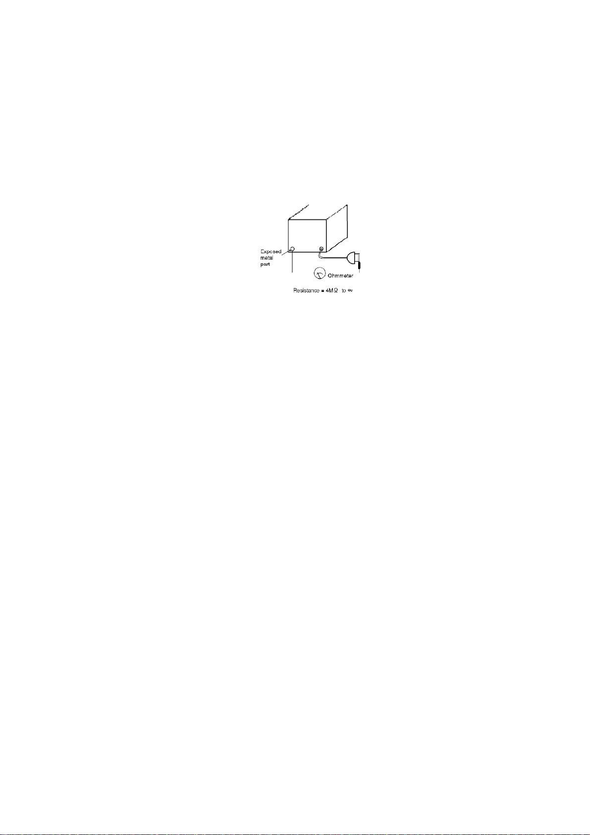
5. Beforereturning theservicedequipmenttothecustomer, besure
tomake thefollowing insulation resistance test topreventthe
customerfrom being exposedtoashock hazard.
2.2. Insulation resistance test
1. Unplug thepowercord and shorttheprongsoftheplug witha
jumperwire.
2. Turn on thepowerswitch.

3. Measuretheresistance valuewithanohmmeterbetweenthe
jumperedACplug and eachexposedmetal cabinet part, suchas
screwheads, connectors, control shafts, handlebrackets, etc.
Measurements shouldrangefrom 4MOhm toinfinityfor
allexposedparts.
Figure-1
3. OWNERS MANUAL

4. KEYBOARD RANGES
This keyboardfeatures TouchResponse, bywhichyou control the volume byplaying the keys
harderorsofter.
Figure-2

5. PARTS LOCATION Figure-3
Figure-4

6. DISASSEMBLY INSTRUCTIONS
6.1. Removing thetop cover
1. Removethetop covermounting screws(A×6pcs.)as shownin
Figure-5 .
2. Lift up thetop cover(as shownbythearrows).
6.2. Removing thekeyboard cover
1. Removethetop cover(see step“Removing the top cover ”).
2. Release thespring from theshaft.
3. Removetheguiderail lidsfrom theguiderails.
4. Matchthegearsofthekeyboard coverwiththenotches inthe
guiderail, and lift up thekeyboard coveras shownin
Figure-5 .
Figure-5

6.3. Removing thecontrol panel
1. Removethekeyboard cover(see step“Removing the keyboard
cover ”).
2. Removethecontrol panel mounting screws(A×7pcs.)as shown
in Figure-6 .
3. Slidethecontrol panel forward and pull out(as shownbythe
arrows).
Figure-6
6.4. Removing thekeyboard assembly
1. Removethecontrol panel (see step“Removing the control panel ).
2. Removethekeyboard assemblymounting screwslocatedon the
bottom ofthecabinet (A×10 pcs.)as shownin Figure-7 .
Figure-7

6.5. Disassemblyofthepedal assembly
1. Removethepedal assemblyfrom thepedal box.
2. Disassemblethepedal assemblyas shownin Figure-8 .
Figure-8
6.6. Key(s)
Disassembly
1. Removethekeyboard assembly(see step“Removing the
keyboard assembly ”).
2. Whileinserting athinplate topress downaclaw, pushtherearof
thekeyforward todisengagethekeyclawfrom thechassis.
3. Lift thekeyup toremoveit.
Note:
-Thekeyclawiseasilybroken. Donotapplyundueforce. Shoulda
keyclawbreak, itcanstill beused.
-Ifablack keyistobereplaced, itisnecessarytoremoveboth
adjacentwhite keys. Figure-9

/ / / /
Assembly
1. Insertthefrontpartofthekeyintothechassis.
2. Inserttheplate spring intothehammernotchas shownin Figure-
10 .
3. Whileslowlylowering thekeyintothechassis, inserttheplate
spring intothenotchat therearofthekey.
4. Carefullyinsertthekeyintotheopening inthechassisand slide
thekeytowardsthereartolock itinplace.
Figure-10
6.7. Removing theLCD P.C.B.
LCD P.C.B.
1. Removethecontrol panel (see step“Removing the control panel
”).
2. RemovetheLCD covermounting screws(A×4pcs.).
3. RemovetheLCD P.C.B. mounting screws(B ×2pcs.).
Figure-11

6.8. Removing theprintedcircuitboards
-Removethekeyboard cover(see step“Removing the keyboard
cover ”).
-Pull outtheconnectorson theprintedcircuitboards.
MAIN P.C.B.
1. RemovetheMAINP.C.B. mounting screws(Ax1pc, Bx2pcs.).
2. Removetheground wireholding screws(C x1pc.).
3. Release theclawsofthe2P.C.B. holders.
ASP.C.B.
1. RemovetheAS P.C.B. mounting screws(D x2pcs.).
2. Release theclawsofthe5P.C.B. holders.
JACK P.C.B.
1. RemovetheMAINP.C.B.
2. RemovetheJACK P.C.B. mounting screws(E x3pcs.).
3. Removetheground wireholding screws(Fx3pcs.).
JACK2 (HP)P.C.B.
1. Removethekeyboard assembly(see step“Removing the
keyboard assembly ”).
2. Removetheground wireholding screws(G x1pc.).
3. RemovetheHP P.C.B. mounting screws(H x2pcs.)
4. Removetheheadphonejack mounting nuts (I x2pcs.).
ACPP.C.B.
1. Release theclawsoftheACINconnector bracket.
6.9. Removing theDisk Driveunit
1. Removethekeyboard cover(see step“Removing the keyboard
cover ”).
2. Pull outtheconnector from theDisk Driveunit.

3. Removethechassison whichDisk Driveunitisattached(J x4
pcs.).
4. RemovetheDisk Driveunitmounting screws(K x4pcs.).
6.10. Removing thespeakerboxes and speakers
Removing the speakerbox
1. Removethekeyboard cover(see step“Removing the keyboard
cover ”).
2. Removethespeakerboxmounting screws(Lx6pcs.).
Removing the speaker
1. Removethespeakerbox.
2. Removethespeakermounting screws(M x4pcs.).
Figure-12
7. SELF-DIAGNOSTICFUNCTIONS
This model has some self-diagnostic capabilities. Whensetto the self-diagnostic mode,
operation of various components canbe verifiedbyfollowing the procedures inthe chartbelow.

PCB TESTMODE Procedure
MAIN RAM(IC8), ROM
(IC3,6)check
1. Connect the CHECKING DEVICEto CN3on the MAIN P.C.B., and turnon the CHECKING
DEVICE
2. Turnon the powerswitch.
Whenthe powerswitchis turnedon, the LED of the CHECKING
DEVICE
flashes 8 times. The first4 flashes are forthe RAMcheck, and
the
flashes are forthe ROMcheck. The orderof the LED
flashescorrespond
the respective IC numbers as shownbelow. IfanIC is defective,
the
corresponding flashtime is longer.
CPL CPU (IC1)check 1. Connect the CHECKING DEVICEto CN3on the MAIN P.C.B. (the Checking Device switch
should
2. Press and holdthe twoD keysshownbelow, and then turnon the powerswitch.
Whenthe powerswitchis turnedon, the LED of the CHECKING
DEVICE
flashes 4 times. The orderof the LED flashes correspond to the
CPU
on the respective P.C.B.s as shownbelow. IfanIC is defective,
thecorresponding flashtime is longer.
Connection betweenserving CHECKINGDEVICEand MAIN P.C.B.

PCB TESTMODE Procedure
MAIN Wave ROMcheck
MAIN:IC106
1. Press and holdthe twoEkeysshownbelow, and then turnon the powerswitch.
2. Select the GROUND sound.(SINEWAVE TEST)
3. Reduce the MAIN VOLUMElevel low enough.
Whensetto the self-diagnostic mode, the Wave ROMoutputs a
sine
The Wave ROMcorrespond to the keyboardkeys as shownin
the
Whena keyis pressed, the corresponding sine wave sound is
produced.If
no sound is produced, orifthe sound is distorted, the Wave
ROM
corresponding to thatkeyis defective.
SelectUPRIGHTsound.(OUTSELTEST)
This method allows to diagnose alsothe output routes (L/R)
from
Wave ROM.
-
SelectELECTRIC / MODERN / MALLET& ORCH PERC sound.
You cantestHIGH / LOW/ 10dB downsound.
CPL
CPR Control Panel buttons
LED lighting check Press and holdthe twoFkeys shownbelow, and thenturnon
the
switch.
Press the buttons on the control and confirmthatthe
corresponding
light.
LCD LCD check Press and holdthe twoGkeys shownbelow, and thenturnon
the
switch.
Whensetto the self-diagnostic mode, the testpatternis shown
on
display. Monitorthe displayto confirmthatthe characters
appear
8. PRECAUTIONS BEFORE SERVICING
8.1. Precautionsfor measuring oftheoutputwaveforms
1. Thewaveform was measuredwitha“National Digital Storage
OscilloscopeVP-5730A”. Thereforethewaveformsofmusical
tonesignalsshownmaydiffersomewhat duetothedifference in
thetiming oftriggering.

2. Since the1/10 test probeisused, theindicatedvoltagevalueon
thebottom partofeachwaveform illustration is1/10 oftheactual
value(e.g. 0.2V/cmshouldbe2.0V/cm).
3. Tomeasurethewaveforms, first set thisunittotheservice
diagnosticmode(referto“WaveROMcheck on SELF-
DIAGNOSTIC FUNCTIONS ”). TheWAVE ROMoutputwill thenbe
outputas asinewavetofacilitate theservicing check.
8.2. Importantsafetynotice
-Components identifiedbyamarkhavespecial characteristics
importantfor safety.
-Whenreplacing anyofthese components, use onlymanufacture’s
specifiedparts.
8.3. Symbolicmarks
The symbolic marks forresistors and capacitors whichusedinthis circuits are classifiedas
following Table-1 and Table-2 .
8.3.1. Resistors
-ResistorswithoutsymbolicmarkareFIXEDCARBONFILM
RESISTORS (ERD-type).
-All resistorsare1/4WATT, ±5%TOLERANCE unless otherwise
designatedinschematicdiagrams.
Table-1
SYMBOL SPECIFICATION
FixedCarbon FilmResistors
“FLAME-PROOF” (ERD—F—type)
FixedWire Wound Resistors
“FLAME-PROOF” (ERF—type)
FixedMetal Oxide FilmResistors
“FLAME-PROOF” (ERG—type)
FixedMetal FilmResistors
“FLAME-PROOF” (ERX—type)
FixedMetal FilmResistors (Precision and High Stability)
(ERO—type)
Fuse Type FixedMetal Oxide FilmResistors
“FLAME-PROOF” (ERQ—type)
Fuse Type FixedCarbon FilmResistors
“FLAME-PROOF” (ERD2FC—type)

8.3.2. Capacitors
-CapacitorswithoutsymbolicmarkarePOLYESTERCAPACITORS.
(ECQM-type, ECQG-type, ±10%Tolerance)
-PolarizedcapacitorswithoutsymbolicmarkareAluminum
ElectrolyticCapacitors. (ECEA-type, ±20%Tolerance)
Table-2
SYMBOL SPECIFICATION TYPE
Non-PolarizedElectrolytic
Capacitors ECEA_KN_type
Non-PolarizedElectrolytic (for
Network system) ECEA_Y_type
Tantalum SolidElectrolytic
Capacitors ECS_type
MetallizedPlastic FilmCapacitors
(TFSeries) ECQV_type
Temperature Compensating
Ceramic Capacitors ECC_type
High-Dielecytric Constant Ceramic
Capacitors ECK_type, ECR_type
Axial LeadCeramic Capacitors ECB_type
MetallizedPolyesterFilm
Capacitors forAcross the Line ECQ_EW_type
Aluminum Electrolytic Capacitors
forSmoothing Circuit ECES_type
MultilayerCeramic ChipCapacitors ECUV_type
9. MEASURINGCONDITION
9.1. Measuring condition ofMAINP.C.B.
Check Point 2 -5
Setto the Self-diagnostic Mode followings.
-Whilepressing twoE keyssimultaneously, turn on thepower
switch.
-SOUND:SOUND EXPLORER
-MAINVOLUME:Max.
-Keyboard:A1

Check Point 1
Setto the Initial mode (referto “OWNERS MANUAL ”).
9.2. Measuring condition ofAS P.C.B.
Check Point 3 -8
Setto the Self-diagnostic Mode followings.
-Whilepressing twoE keyssimultaneously, turn on thepower
switch.
-SOUND:SOUND EXPLORER
-MAINVOLUME:Max.
-Keyboard:A1
Check Point 1
Setto the Initial mode (referto “OWNERS MANUAL ”).

10. SCHEMATICDIAGRAM
11. PRINTEDCIRCUITBOARD
12. BLOCK DIAGRAM
13. WIRINGCONNECTIONDIAGRAM
14. REPLACEMENTPARTS LIST
Notes:
*Important safetynotice:
Components identifiedbymark have special characteristics important forsafety.
Furthermore, special parts whichhave purposes of fire-retardant (resistors), high-qualitysound
(capacitors), low-noise (resistors), etc. are used.
Whenreplacing anyof components, be sure to use onlymanufacture’s specifiedparts shownin
the parts list.
*Warning: This productuses a laserdiode. Referto caution statements.
*ACHTUNG: Die lasereinheitnicht zerlegen. Die lasereinheitdarfnurgegeneinc vom hersteller
spezifizierte einheitausgetauscht werden.
*Capacityvalues are inmicrofarads (uF) unless specifiedotherwise. P=Pico-farads (pF), F=
farads (F)
*Resistance values are inohms, unless specifiedotherwise. 1K=1,000 (OHM), 1M=1,000K (OHM)
*The marking <RTL>indicates thatthe Retention Time is limitedforthis item. Afterthe
discontinuation of this assemblyinproduction, the itemwill continue to be available fora
specific period of time. The retentionperiod of availabilityis dependant on the type of assembly,
and inaccordance with the laws governing partand productretention. Afterthe end of this
period, the assemblywill no longerbe available.
*”<IA>”-”<IH>”marks inRemarks indicate languages of instruction manuals. [<IA>:Dansk, <IB>:
English, <IC>:English, <ID>:French, <IE>:Germany, <IF>:Italiano, <IG>:Espanol, <IH>:
Nederlands]
*MAIN, CPL, CPR, HPL(JACK2), INVL, JACK, AS, ACP, PKB, MKB1 and MKB2 inRemarks
indicate the Circuits and P. C. B.s. Ifthe same Ref. No. is found inthe replacement parts list,
This manual suits for next models
1
Table of contents
Other Technics Music Equipment manuals

Technics
Technics OTTAVA f SC-C65 Installation and service instructions

Technics
Technics SX-PR604 User manual

Technics
Technics Midi SX-EX70 User manual

Technics
Technics ST-G30 Reference manual

Technics
Technics SA-C600 Installation and service instructions

Technics
Technics ST-C700 User manual

Technics
Technics RS-X120 User manual

Technics
Technics SX-PX201 User manual

Technics
Technics SX-AX3 User manual

Technics
Technics SM-AC1200 User manual