Avid Technology Pro Tools S6 Master Post Module User manual

S6 Installation Guide
For Avid S6 M10 and S6 M40 Systems

Legal Notices
© 2014 Avid Technology, Inc., ("Avid"), all rights reserved. This guide may not
be duplicated in whole or in part without the written consent of Avid.
003, 192 Digital I/O, 192 I/O, 96 I/O, 96i I/O, Adrenaline, AirSpeed, ALEX,
Alienbrain, AME, AniMatte, Archive, Archive II, Assistant Station, AudioPages,
AudioStation, AutoLoop, AutoSync, Avid, Avid Active, Avid Everywhere, Avid
Advanced Response, Avid DNA, Avid DNxcel, Avid DNxHD, Avid DS Assist
Station,AvidIgnite,AvidLiquid,AvidMediaEngine,AvidMediaProcessor,Avid
MEDIArray, Avid Mojo, Avid Remote Response, Avid Unity, Avid Unity ISIS,
Avid VideoRAID, AvidRAID, AvidShare, AVIDstripe, AVX, Beat Detective,
Beauty Without The Bandwidth, Beyond Reality, BF Essentials, Bomb Factory,
Bruno, C|24, CaptureManager, ChromaCurve, ChromaWheel, Cineractive
Engine, Cineractive Player, Cineractive Viewer, Color Conductor, Command|8,
Control|24, Cosmonaut Voice, CountDown, d2, d3, DAE, D-Command,
D-Control,Deko,DekoCast,D-Fi,D-fx,Digi002, Digi003,DigiBase,Digidesign,
Digidesign Audio Engine, Digidesign Development Partners, Digidesign
Intelligent Noise Reduction, Digidesign TDM Bus, DigiLink, DigiMeter,
DigiPanner, DigiProNet, DigiRack, DigiSerial, DigiSnake, DigiSystem, Digital
Choreography, Digital Nonlinear Accelerator, DigiTest, DigiTranslator,
DigiWear, DINR, DNxchange, Do More, DPP-1, D-Show, DSP Manager,
DS-StorageCalc, DV Toolkit, DVD Complete, D-Verb, Eleven, EM, Euphonix,
EUCON, EveryPhase, Expander, ExpertRender, Fairchild, FastBreak, Fast
Track, Film Cutter, FilmScribe, Flexevent, FluidMotion, Frame Chase, FXDeko,
HD Core, HD Process, HDpack, Home-to-Hollywood, HyperSPACE,
HyperSPACE HDCAM, iKnowledge, Impact, Improv, iNEWS, iNEWS Assign,
iNEWS ControlAir, InGame, Instantwrite, Instinct, Intelligent Content
Management, Intelligent Digital Actor Technology, IntelliRender, Intelli-Sat,
Intelli-Sat Broadcasting Recording Manager, InterFX, Interplay, inTONE,
Intraframe, iS Expander, iS9, iS18, iS23, iS36, ISIS, IsoSync, LaunchPad,
LeaderPlus, LFX, Lightning, Link & Sync, ListSync, LKT-200, Lo-Fi,
MachineControl, Magic Mask, Make Anything Hollywood, make manage
move|media, Marquee, MassivePack, MassivePack Pro, Maxim, Mbox, Media
Composer, MediaFlow, MediaLog, MediaMix, Media Reader, Media Recorder,
MEDIArray, MediaServer, MediaShare, MetaFuze, MetaSync, MIDI I/O, Mix
Rack, Moviestar, MultiShell, NaturalMatch, NewsCutter, NewsView,
NewsVision, Nitris, NL3D, NLP, NSDOS, NSWIN, OMF, OMF Interchange,
OMM, OnDVD, Open Media Framework, Open Media Management, Painterly
Effects, Palladium, Personal Q, PET, Podcast Factory, PowerSwap, PRE,
ProControl, ProEncode, Profiler, Pro Tools, Pro Tools|HD, Pro Tools LE, Pro
Tools M-Powered, Pro Transfer, QuickPunch, QuietDrive, Realtime Motion
Synthesis,Recti-Fi, ReelTapeDelay,Reel TapeFlanger,ReelTapeSaturation,
Reprise, Res Rocket Surfer, Reso, RetroLoop, Reverb One, ReVibe,
Revolution, rS9, rS18, RTAS, Salesview, Sci-Fi, Scorch, ScriptSync,
SecureProductionEnvironment, Shape-to-Shape, ShuttleCase, Sibelius,
SimulPlay, SimulRecord, Slightly Rude Compressor, Smack!, Soft SampleCell,
Soft-Clip Limiter, SoundReplacer, SPACE, SPACEShift, SpectraGraph,
SpectraMatte, SteadyGlide, Streamfactory, Streamgenie, StreamRAID,
SubCap, Sundance, Sundance Digital, SurroundScope, Symphony, SYNC HD,
SYNC I/O, Synchronic, SynchroScope, Syntax, TDM FlexCable, TechFlix,
Tel-Ray,Thunder,TimeLiner,Titansync,Titan,TLAggro,TL AutoPan, TL Drum
Rehab,TL Everyphase, TL Fauxlder,TL In Tune, TLMasterMeter, TL Metro, TL
Space, TL Utilities, tools for storytellers, Transit, TransJammer, Trillium Lane
Labs, TruTouch, UnityRAID, Vari-Fi, Video the Web Way, VideoRAID,
VideoSPACE, VTEM, Work-N-Play, Xdeck, X-Form, and XMON are either
registered trademarks or trademarks of Avid Technology, Inc. in the United
States and/or other countries. The Interplay name is used with the permission
of the Interplay Entertainment Corp. which bears no responsibility for Avid
products. All other trademarks are the property of their respective owners.
Bonjour, the Bonjour logo, and the Bonjour symbol are trademarks of Apple
Computer, Inc.
Thunderbolt and the Thunderbolt logo are trademarks of Intel Corporation in the
U.S. and/or other countries.
Portions of this software are copyright 2009 The FreeType Project
(www.freetype.org). All rights reserved.
This product may include software developed by the OpenSSL Project for use
in the OpenSSL Toolkit (http://www.openssl.org/).
This product may be protected by one or more U.S. and non-U.S. patents.
Details are available at www.avid.com/patents.
Product features, specifications, system requirements, and availability are
subject to change without notice.
Guide Part Number 9320-65199-00 REV C 02/14

Contents iii
Part I Introduction
Chapter 1. Introduction . . . . . . . . . . . . . . . . . . . . . . . . . . . . . . . . . . . . . . . . . . . . . . . . . . . . . . . . . . . . . . . . . . . . . . . . . . 1
Overview of Installation. . . . . . . . . . . . . . . . . . . . . . . . . . . . . . . . . . . . . . . . . . . . . . . . . . . . . . . . . . . . . . . . . . . . . . 2
What’s Included . . . . . . . . . . . . . . . . . . . . . . . . . . . . . . . . . . . . . . . . . . . . . . . . . . . . . . . . . . . . . . . . . . . . . . . . . . . 2
System Requirements and Compatibility . . . . . . . . . . . . . . . . . . . . . . . . . . . . . . . . . . . . . . . . . . . . . . . . . . . . . . . . . 3
Activation and Registration . . . . . . . . . . . . . . . . . . . . . . . . . . . . . . . . . . . . . . . . . . . . . . . . . . . . . . . . . . . . . . . . . . . 3
About This Guide . . . . . . . . . . . . . . . . . . . . . . . . . . . . . . . . . . . . . . . . . . . . . . . . . . . . . . . . . . . . . . . . . . . . . . . . . . 4
About www.avid.com . . . . . . . . . . . . . . . . . . . . . . . . . . . . . . . . . . . . . . . . . . . . . . . . . . . . . . . . . . . . . . . . . . . . . . . 4
Chapter 2. Modules and Configuration Overview . . . . . . . . . . . . . . . . . . . . . . . . . . . . . . . . . . . . . . . . . . . . . . . . . . . . . 5
Master Section Modules . . . . . . . . . . . . . . . . . . . . . . . . . . . . . . . . . . . . . . . . . . . . . . . . . . . . . . . . . . . . . . . . . . . . . 5
Module Layout . . . . . . . . . . . . . . . . . . . . . . . . . . . . . . . . . . . . . . . . . . . . . . . . . . . . . . . . . . . . . . . . . . . . . . . . . . . . 8
Part II Frames
Chapter 3. Assembling Legs . . . . . . . . . . . . . . . . . . . . . . . . . . . . . . . . . . . . . . . . . . . . . . . . . . . . . . . . . . . . . . . . . . . . . 13
Unpack the Leg Frames . . . . . . . . . . . . . . . . . . . . . . . . . . . . . . . . . . . . . . . . . . . . . . . . . . . . . . . . . . . . . . . . . . . . 13
Overview of Leg Frame Assembly. . . . . . . . . . . . . . . . . . . . . . . . . . . . . . . . . . . . . . . . . . . . . . . . . . . . . . . . . . . . . 13
Attaching the Back Beam . . . . . . . . . . . . . . . . . . . . . . . . . . . . . . . . . . . . . . . . . . . . . . . . . . . . . . . . . . . . . . . . . . . 14
Attaching the Front Beam . . . . . . . . . . . . . . . . . . . . . . . . . . . . . . . . . . . . . . . . . . . . . . . . . . . . . . . . . . . . . . . . . . . 15
Attaching the Back Corner Brackets . . . . . . . . . . . . . . . . . . . . . . . . . . . . . . . . . . . . . . . . . . . . . . . . . . . . . . . . . . . 16
Attaching the End Shelves . . . . . . . . . . . . . . . . . . . . . . . . . . . . . . . . . . . . . . . . . . . . . . . . . . . . . . . . . . . . . . . . . . 17
Leveling the Leg Frame . . . . . . . . . . . . . . . . . . . . . . . . . . . . . . . . . . . . . . . . . . . . . . . . . . . . . . . . . . . . . . . . . . . . 17
How to Proceed . . . . . . . . . . . . . . . . . . . . . . . . . . . . . . . . . . . . . . . . . . . . . . . . . . . . . . . . . . . . . . . . . . . . . . . . . . 18
Chapter 4. Assembling Frame Chassis . . . . . . . . . . . . . . . . . . . . . . . . . . . . . . . . . . . . . . . . . . . . . . . . . . . . . . . . . . . . 19
Before You Begin. . . . . . . . . . . . . . . . . . . . . . . . . . . . . . . . . . . . . . . . . . . . . . . . . . . . . . . . . . . . . . . . . . . . . . . . . 19
Assembling the Chassis . . . . . . . . . . . . . . . . . . . . . . . . . . . . . . . . . . . . . . . . . . . . . . . . . . . . . . . . . . . . . . . . . . . . 21
Attaching the Back Feet . . . . . . . . . . . . . . . . . . . . . . . . . . . . . . . . . . . . . . . . . . . . . . . . . . . . . . . . . . . . . . . . . . . . 25
Attaching the Bolster . . . . . . . . . . . . . . . . . . . . . . . . . . . . . . . . . . . . . . . . . . . . . . . . . . . . . . . . . . . . . . . . . . . . . . 28
Installing Display Module Mounting Brackets . . . . . . . . . . . . . . . . . . . . . . . . . . . . . . . . . . . . . . . . . . . . . . . . . . . . . 29
Installing Rear Panel Mounting Brackets . . . . . . . . . . . . . . . . . . . . . . . . . . . . . . . . . . . . . . . . . . . . . . . . . . . . . . . . 30
Installing Side Covers. . . . . . . . . . . . . . . . . . . . . . . . . . . . . . . . . . . . . . . . . . . . . . . . . . . . . . . . . . . . . . . . . . . . . . 31
How to Proceed . . . . . . . . . . . . . . . . . . . . . . . . . . . . . . . . . . . . . . . . . . . . . . . . . . . . . . . . . . . . . . . . . . . . . . . . . . 32
Contents

S6 Installation Guideiv
Part III Modules
Chapter 5. Installing the Power Strip, PSUs, Switches, and Cables . . . . . . . . . . . . . . . . . . . . . . . . . . . . . . . . . . . . . 35
Overview . . . . . . . . . . . . . . . . . . . . . . . . . . . . . . . . . . . . . . . . . . . . . . . . . . . . . . . . . . . . . . . . . . . . . . . . . . . . . . . 35
Installing the Power Strip . . . . . . . . . . . . . . . . . . . . . . . . . . . . . . . . . . . . . . . . . . . . . . . . . . . . . . . . . . . . . . . . . . . 36
Ethernet Switch and PSU Placement per System Configuration . . . . . . . . . . . . . . . . . . . . . . . . . . . . . . . . . . . . . . . 37
Installing the Ethernet Switch . . . . . . . . . . . . . . . . . . . . . . . . . . . . . . . . . . . . . . . . . . . . . . . . . . . . . . . . . . . . . . . . 40
Installing PSUs. . . . . . . . . . . . . . . . . . . . . . . . . . . . . . . . . . . . . . . . . . . . . . . . . . . . . . . . . . . . . . . . . . . . . . . . . . . 41
Installing and Connecting Cabling . . . . . . . . . . . . . . . . . . . . . . . . . . . . . . . . . . . . . . . . . . . . . . . . . . . . . . . . . . . . . 44
Attaching the Outer Side Covers . . . . . . . . . . . . . . . . . . . . . . . . . . . . . . . . . . . . . . . . . . . . . . . . . . . . . . . . . . . . . . 50
How to Proceed . . . . . . . . . . . . . . . . . . . . . . . . . . . . . . . . . . . . . . . . . . . . . . . . . . . . . . . . . . . . . . . . . . . . . . . . . . 52
Chapter 6. Installing Modules . . . . . . . . . . . . . . . . . . . . . . . . . . . . . . . . . . . . . . . . . . . . . . . . . . . . . . . . . . . . . . . . . . . . 53
Installing Modules. . . . . . . . . . . . . . . . . . . . . . . . . . . . . . . . . . . . . . . . . . . . . . . . . . . . . . . . . . . . . . . . . . . . . . . . . 54
Installing Fill Panels . . . . . . . . . . . . . . . . . . . . . . . . . . . . . . . . . . . . . . . . . . . . . . . . . . . . . . . . . . . . . . . . . . . . . . . 60
Installing Display Modules. . . . . . . . . . . . . . . . . . . . . . . . . . . . . . . . . . . . . . . . . . . . . . . . . . . . . . . . . . . . . . . . . . . 60
Chapter 7. How to Proceed . . . . . . . . . . . . . . . . . . . . . . . . . . . . . . . . . . . . . . . . . . . . . . . . . . . . . . . . . . . . . . . . . . . . . . 63
Starting Up and Shutting Down . . . . . . . . . . . . . . . . . . . . . . . . . . . . . . . . . . . . . . . . . . . . . . . . . . . . . . . . . . . . . . . 63
Activate and Register . . . . . . . . . . . . . . . . . . . . . . . . . . . . . . . . . . . . . . . . . . . . . . . . . . . . . . . . . . . . . . . . . . . . . . 63
Complete the Hardware Assembly . . . . . . . . . . . . . . . . . . . . . . . . . . . . . . . . . . . . . . . . . . . . . . . . . . . . . . . . . . . . 64
Updating S6 System Software. . . . . . . . . . . . . . . . . . . . . . . . . . . . . . . . . . . . . . . . . . . . . . . . . . . . . . . . . . . . . . . . 67
Configuring the S6 System . . . . . . . . . . . . . . . . . . . . . . . . . . . . . . . . . . . . . . . . . . . . . . . . . . . . . . . . . . . . . . . . . . 68
Part IV Appendices
Appendix A. Expanding or Disassembling S6. . . . . . . . . . . . . . . . . . . . . . . . . . . . . . . . . . . . . . . . . . . . . . . . . . . . . . . 71
Overview . . . . . . . . . . . . . . . . . . . . . . . . . . . . . . . . . . . . . . . . . . . . . . . . . . . . . . . . . . . . . . . . . . . . . . . . . . . . . . . 71
Removing Modules. . . . . . . . . . . . . . . . . . . . . . . . . . . . . . . . . . . . . . . . . . . . . . . . . . . . . . . . . . . . . . . . . . . . . . . . 71
Disassembling a Frame . . . . . . . . . . . . . . . . . . . . . . . . . . . . . . . . . . . . . . . . . . . . . . . . . . . . . . . . . . . . . . . . . . . . 72
Appendix B. Compliance . . . . . . . . . . . . . . . . . . . . . . . . . . . . . . . . . . . . . . . . . . . . . . . . . . . . . . . . . . . . . . . . . . . . . . . . 73
Environmental Compliance . . . . . . . . . . . . . . . . . . . . . . . . . . . . . . . . . . . . . . . . . . . . . . . . . . . . . . . . . . . . . . . . . . 73
EMC (Electromagnetic Compliance) . . . . . . . . . . . . . . . . . . . . . . . . . . . . . . . . . . . . . . . . . . . . . . . . . . . . . . . . . . . 74
Safety Compliance . . . . . . . . . . . . . . . . . . . . . . . . . . . . . . . . . . . . . . . . . . . . . . . . . . . . . . . . . . . . . . . . . . . . . . . . 75

Part I: Introduction

Chapter 1: Introduction 1
Chapter 1: Introduction
Avid®S6 is a professional, modular, ergonomically designed control surface for Avid Pro Tools®and other EUCON™-compatible
DAWs (Digital Audio Workstations). S6 is flexible and scalable, letting you choose the best system for your needs. Many different
configurations are possible with different numbers of faders, knobs, and displays. All systems let you place the master section in
any position, left-to-right, within a frame. More fader strips, knobs-per-strip, or displays can be added later.
This guide explains how to assemble the system frame, how to install modules, and how to configure your S6 system.
Before You Begin
• Make sure your workspace is clean, dry, is well lighted, and has ample room to work.
• Make sure you have a sturdy table or other flat surface, preferably with padding to protect the hardware. (If your system includes
Legs, you will use the Leg Frame instead of a table.)
• Make sure you have another person available to help lift, turn, and move the system during and after assembly.
• Identify and organize the packages that make up your purchased system (see Figure 1) to simplify the assembly process.All re-
quired tools are in the Side Covers package (see “What’s Included” on page 2)
1 – Master Module
Includes this guide and your M10 or M40 Master Module.
2 – Frame Components
Chassis kits, Side Covers, Bolster, and Rear Panel packages.
3 – Power and Connectivity
Power Supply Units (PSUs), Ethernet switch(es), Power Strip, and Cable Sets.
4 – Modules
Automation, Fader, Process, Knob, and Display Modules (the number and type vary depending on configuration).
Components and systems are heavy! Team lift, always. We recommend four people, one lifting each corner. Never attempt to move
systems that are five or more chassis in width. Disassemble it first (see Appendix A, “Expanding or Disassembling S6”). Also,
never move or lift a chassis (any size) by the Side Covers, Bolster, or Rear Panels (they can break). Move or lift while holding on
to the metal chassis (frame) instead.
Figure 1. Packages organized before assembling an example S6 M10 16-5 system:
1
3
2
4

S6 Installation Guide2
Overview of Installation
1Determine module layout (“Modules and Configuration Overview” on page 5)
2Assemble the frame
• Assemble Legs if your system includes them (“Assembling Legs” on page 13)
• Assemble the Frame Chassis kits (“Assembling Frame Chassis” on page 19)
3Install modules
• Install the Ethernet switch, power supplies and cables (“Installing the Power Strip, PSUs, Switches, and Cables” on page 35)
• Install modules (“Installing Modules” on page 53)
4Start up your system to confirm module communication, then complete the hardware assembly (Chapter 7, “How to Proceed”)
5Activate your system purchase online, then log into your Avid Master Account to download and install S6 software updates,
Workstation installers, S6 documentation and other resources (“Updating S6 System Software” on page 67)
What’s Included
The Master Module package contains the following items:
• Master Module (M10 or M40)
• This guide (S6 Installation Guide), which contains the following items in the front pouch of the binder:
• Activation Card
• Registration Card
• System Restore USB Flash Drive
•Health & Safety Guide
Tools
The following tools are required for assembly of the S6 frame and are included in the Side Covers package:
• Hex M2.5
• Hex M3
• Hex M4
• Hex M5
• Hex M6
• Phillips screwdriver #1 (long)
• Phillip screw driver #2
• Small flat screw driver
Legs
The following tools are included with the Leg Set package (not all systems include Legs):
• One open end wrench (13 mm)
Additional Required Components
The following items are required to use S6 and must be purchased separately:
• USB Flash drive to use when transferring and installing S6 system software updates
• Workstation running Pro Tools or other EUCON-compatible digital audio workstation (see Avid.com for compatibility
information)
Do not use the System Restore drive for anything other than S6 System Restore software. Do not use this drive to store audio files
or any other data or software.

Chapter 1: Introduction 3
Optional
The following items are recommended and can be purchased separately:
• UPS (Uninterruptable Power Supply), power conditioner/timer, or other power management system
• USB computer keyboard and mouse/trackball (the Master Module provides a touchscreen keyboard, but you might prefer to
use a dedicated keyboard/mouse/trackball for some administrative or troubleshooting tasks)
System Requirements and Compatibility
Avid can only assure compatibility and provide support for hardware and software it has tested and approved.
For complete system requirements and a list of qualified computers, operating systems, hard drives, and third-party devices, visit:
www.avid.com/compatibility
Activation and Registration
Review the enclosed Activation Card and Registration Information Card and follow the instructions to Activate (required) and Reg-
ister (optional, but highly recommended). These cards are located in the pouch at the front of this guide.
Activate S6 System Software Immediately
As soon as you have assembled your S6 system and confirmed a successful hardware installation, activate your S6 system software
on-line. Use the alphanumeric code on the included S6 System Software Activation Card to activate and download all S6 system
software and documentation.
Registering
By registering, you become eligible to receive the following:
• Technical support information
• Software update and upgrade notices
• Hardware warranty information
Be sure to Activate your purchase using the enclosed Activation card so you can receive software updates directly in your Avid
account. Check your Avid account for system software updates, Workstation software, and XMON EUCON software

S6 Installation Guide4
About This Guide
This guide explains how to assemble your Avid S6 system.
Conventions Used in This Guide
All of our guides use the following conventions to indicate menu choices and key commands:
:
The names of Commands, Options, and Settings that appear on-screen are in a different font.
The names of switches and keys on the control surface are shown in bold (such as SEL).
The following symbols are used to highlight important information:
About www.avid.com
The Avid website (www.avid.com) is your best online source for information to help you get the most out of your Avid system. The
following are just a few of the services and features available.
Product Registration and Activation
Register your purchase online, and activate
Support and Downloads
Contact Avid Customer Success (technical support); download software updates and the latest online
manuals; browse the Compatibility documents for system requirements; search the online Knowledge Base or join the worldwide
Avid community on the User Conference.
Training and Education
Study on your own using courses available online or find out how you can learn in a classroom setting at
a certified Avid training center.
Products and Developers
Learn about Avid products; download demo software or learn about our Development Partners and their
plug-ins, applications, and hardware.
News and Events
Get the latest news from Avid or sign up for a product demo.
Convention Action
File > Save Choose Save from the File menu
Control+N Hold down the Control key and press the N key
Control-click Hold down the Control key and click the mouse button
Right-click Click with the right mouse button
User Tips are helpful hints for getting the most from your system.
Important Notices include information that could affect your data or the performance of your system.
Shortcuts show you useful keyboard or mouse shortcuts.
Cross References point to related sections in this guide and other Avid guides.
Chapter 2: Modules and Configuration Overview 5
Chapter 2: Modules and Configuration Overview
This chapter identifies each of the S6 modules, and tells you how and where they can be arranged within a system. Use this infor-
mation to determine your module layout before proceeding with the assembly.
There are two primary types of modules in a system, Master modules and Channel modules.
Master Section Modules
The S6 Master Module and S6 Automation Module are often installed in the same chassis to form a master section.
Master Module
The Master Module is the primary module of the system, providing the Touchscreen, two banks of Soft Keys, a monitoring section
and other controls. Each system must have one Master Module. There are two models of Master Module (M10 and M40) that are
used in S6 M10 or S6 M40 systems, respectively. They share identical controls and features, the only difference are the number of
other modules they each support, and the number of workstations that can be connected.
S6 M10 Systems
These systems include an M10 Master Module that supports up to 10 other S6 modules, and up to two attached
workstations. S6 M10 systems accommodate 8 to 24 faders per frame and are suitable for smaller configurations. Display Modules
are not supported on S6 M10 systems.
S6 M40 Systems
These system include an M40 Master Module that supports up to 40 S6 channel modules and up to 64 fader strips,
including Display Modules. M40 systems support up to eight attached workstations.
Master Module

S6 Installation Guide6
Automation Module
The Automation Module provides transport and locate controls, the Attention fader strip, Jog/Shuttle wheel, a numeric keypad, and
additional Soft Keys. The Automation Module is most often installed directly below and in the same chassis as the Master Module.
Channel Modules
Channel modules combine to form the fader strips of the system, and include the S6 Fader Module, S6 Process Module, S6 Knob
Module, and S6 Display Module. Not all configurations include each type of channel modules.
Fader Module
Each Fader Module provides eight channel faders with meters and other controls. Fader Modules are installed in the first slot of
each chassis (closest to the front).
Process Module
Each Process Module provides eight channel strips, each with a knob, OLED displays and other controls.
Automation Module
Fader Module
Process Module
Chapter 2: Modules and Configuration Overview 7
Knob Module
Each Knob Module provides eight channel strips, each with four dual-function (rotate/press) encoders, OLED displays, and other
controls. Up to two Knob Modules can be installed in the larger chassis M40 systems only.
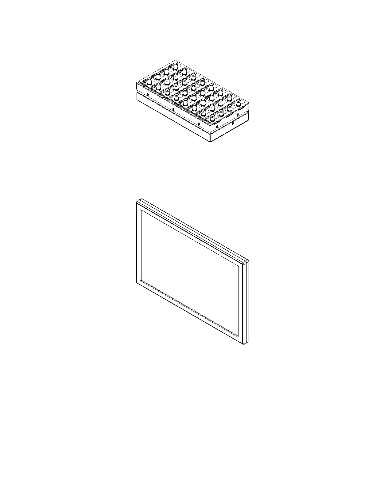
Display Module
(M40 Systems Only)
Display Modules are supported on S6 M40 systems only, and are installed above channel modules. Each Display Module provides
a large display that shows names, meters, waveforms, and other data for up to eight strips.
Knob Module
Display Module

S6 Installation Guide8
Module Layout
This section describes the arrangements of modules front-to-back in their chassis, and chassis left-to-right in the frame.
Front-to-Back Module Arrangements
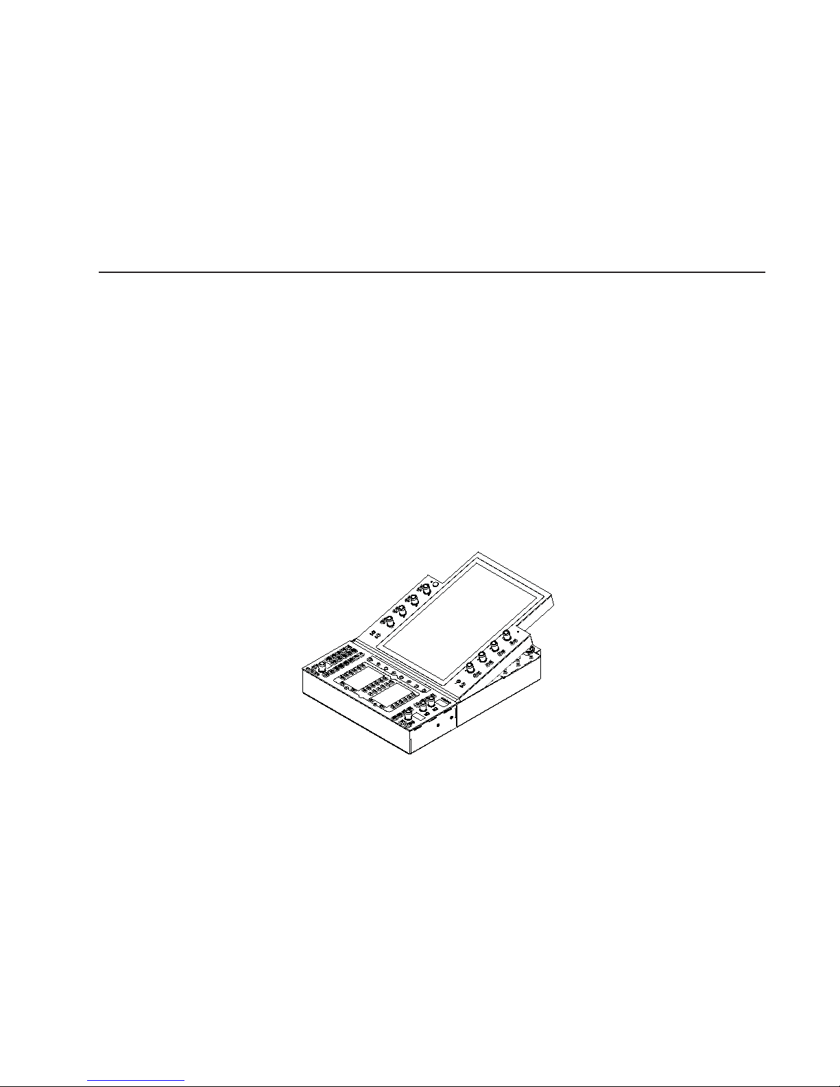
In most configurations, master section modules are installed together in a single chassis with the Master Module above the Auto-
mation Module. They do not have to be in the same chassis, but for simplicity this guide shows them installed together.
Channel modules are usually installed together to provide the fader strips in a system. The Fader Module is installed in slot 1, Pro-
cess Module in slot 2, and Knob Module in slot 3. Frame Chassis Small support one Knob Module per chassis; the Frame Chassis
Large support up to two Knob Modules per chassis. M40-based systems also support Display Modules. Not all slots need to contain
modules. Fill panels are available to cover unused slots.
Master section modules in a Frame Chassis Small
Channel modules in a Frame Chassis Small (left) and a Frame Chassis Large (right)
Slot 1
Slots 2 and 3
Automation Module
Master Module
Fader
Knob
Process
Slot 1
Slot 3
Display
Slot 2
Slot 4
Module
Module
Module
Fader
Knob
Process
Module
Module
Module
Knob
Module
Module
Chapter 2: Modules and Configuration Overview 9
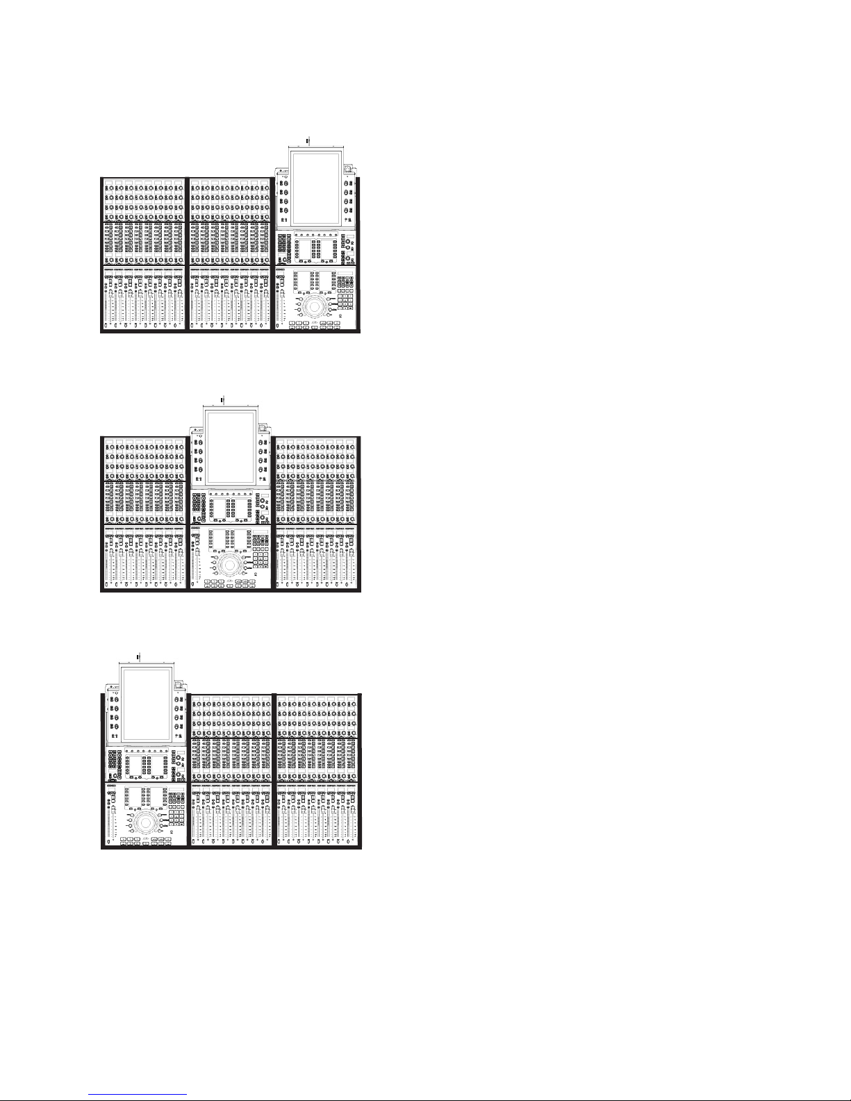
Left-to-Right Chassis and Module Arrangements
Channel sections and the master section modules can be arranged in any order, left-to-right. For example, in an S6 M10–16–5 sys-
tem (16 faders with five knobs per strip) the master section modules can be located in three possible locations, as shown below.
About Custom Module Configurations
While several S6 systems are available in factory configurations that support standard module arrangements, you can customize the
arrangement of modules in many different ways. After you have assembled the system you will use the Touchscreen to tell the sys-
tem where you have installed which modules; as you will see, there are many options for where you can place channel and master
section modules within different chassis.
For now, decide where you want your fader strips to be in relation to the master section modules, then proceed to Part II, “Frames.”
Example 1: S6 M10-16-5 with master section at far right
Example 2: S6 M10-16-5 with master section in the center
Example 3: S6 M10-16-5 with master section at far left

S6 Installation Guide10

Part II: Frames


Chapter 3: Assembling Legs 13
Chapter 3: Assembling Legs
This chapter explains how to assemble the Leg Frames for the S6. Not all systems require Legs. If your system does not include
Leg Frames, please proceed to Chapter 4, “Assembling Frame Chassis.”
Unpack the Leg Frames
Unpack the Legs and Beams and identify the components shown in Figure 1.
1 – Legs
2 – Beams
3 – Beam Mounting Plates
4 – Back Corner Brackets
5 – End Shelves
6 – Fasteners and Tools (not shown)
Overview of Leg Frame Assembly
The Leg Frames consist of two Beams mounted across the back and front of the Legs and secured with Corner Brackets, Left and
Right End Shelves, and leveling feet.
When assembling a Leg Frame as described in the next section, you should start by placing one of the Beams on the floor to gauge
how far apart the Legs need to be. Place the Legs parallel on the floor with proper spacing and put the first Beam across the back
of the Legs, orienting it as shown in the following diagrams and securing it with the Beam Mounting Plates and fasteners. Do not
tighten down fasteners all the way until both Beams and both Back Corner Brackets are in place. Once the back Beam is secured
then place the other Beam across the front and secure it with Beam Mounting Plates and fasteners.
Make sure you have at least one other person available if you need to lift, turn, or move the system during and after assembly. Com-
ponents and systems are heavy! Team lift, always.
Figure 1. Legs Frame components
2
3
4
15

S6 Installation Guide14
Attaching the Back Beam
Attaching the back Beam:
1Place one of the Beams on the floor to determine how far apart the Legs need to be.
2Attach the back beam by doing the following (see Figure 2):
• Put the first Beam across the back of the Legs. Align the pins on the underside of the Beams with the holes in the top of the
Legs. Be sure to orient the back Beam so that the pins on the top are closer to the center of the frame.
• Using four fasteners and washers (included) per mount, secure the Beam with Mounting Plates at each end. Do not tighten
down fasteners all the way until both beams and both Back Corner Brackets are in place.
3Make sure the Beam sits flat on the top of the legs as shown in Figure 3. If necessary, move the legs in or out until the proper
alignment is achieved.
Have someone help hold the components while you position the Beams on the Legs and attach the fasteners.
Fasteners, Washers, and Tools for Legs to Beams
Fastener M8x40
Washer M8
Tool M6 Hex
Figure 2. Attaching a Beam to the Legs using a Beam Mounting Plate
Figure 3. Back view showing correct alignment of Beam on leg (at left), and incorrect alignment (middle, and right)
(Not to scale)

Chapter 3: Assembling Legs 15
Attaching the Front Beam
To attach the front Beam:
1Align the pins on the underside of the Beam with the holes in the top of the Legs. Be sure to orient the front Beam so that the
pins on the top are closer to the center of the frame.
2Using four fasteners and washers (included) per mount, attach the Beam across the front of the Legs using two Beam Mounting
Plates as shown in Figure 4. Do not tighten the fasteners.
Fasteners, Washers, and Tools for Legs to Beams
Fastener M8x40
Washer M8
Tool M6 Hex
Figure 4. Orientation of the pins on the top of the front beam
(Not to scale)
Other manuals for Pro Tools S6 Master Post Module
7
Table of contents
Other Avid Technology Music Equipment manuals

Avid Technology
Avid Technology SC263 User manual

Avid Technology
Avid Technology Pro Tools S6 Master Post Module User manual

Avid Technology
Avid Technology SC264 User manual

Avid Technology
Avid Technology Personal Q User manual

Avid Technology
Avid Technology Pro Tools Quartet User manual

Avid Technology
Avid Technology Pro Tools S6 Master Post Module User manual

Avid Technology
Avid Technology DF70 User manual


