READ COMPLETE SAFETY INSTRUCTIONS AND INSTALLATION TEMPLATE BEFORE STARTING
TEMPLATE MUST BE LEVEL
– TOP –
READ REVERSE SIDE FIRST! READ REVERSE SIDE FIRST!
Figure 1 Figure 2 Figure 3
Catalog No: IM-HUMCRSBP-01
10012707 B2207871A 2.18
90-1067 90-1068 90-1069
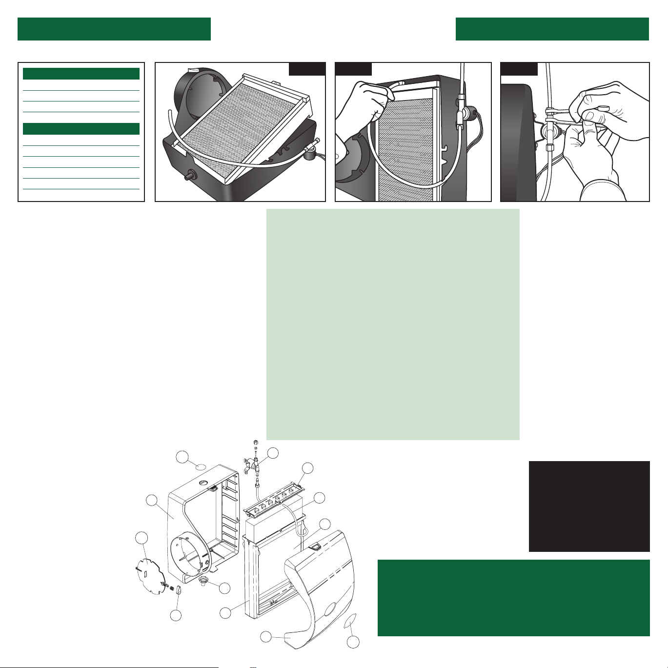
1. Front Cover
2. Base
3. Feed Tube
4. Water Distribution Tray
5. Humidifier Pad
6. Scale Control Insert
7. Integral Damper
8. Damper Handle
9. Drain Spud
10. Hole Plug
11. Nameplate
12. Solenoid Valve
12
10
2
7
9
6
11
1
4
3
5
8
90-1172
FURNISHED ITEMS
ITEMS NOT FURNISHED
Built-in bypass damper
24 VAC Humidifier Control
Saddle valve
Humidifier Installation Template
Mounting screws (sheet metal screws)
Water supply line (1/4” copper)
Drain line (1/2” I.D. hose)
24 VAC Transformer
Low voltage wire
Bypass ductwork
IMPORTANT! Be sure owner’s manual containing instructions
for operation and warranty information is given to owner in order to avoid
unnecessary calls. Warranty is void unless humidifier is installed by
qualified heating and air conditioning contractor due to possible
misapplication of product.
1. Remove front cover by pressing center
tabs on top and bottom of the cover (1) and
base (2). Pull feed tube (3) out of the water
distribution tray (4). Tip the evaporative
assembly forward and lift it out of the
humidifier. (See Figure 1)
2. The humidifier comes assembled for left
side discharge. If converting to right side
discharge, the base can be rotated so round
collar is facing to the right. Swap the location
of the hole plug (10) and drain spud (9) if using
a right side discharge. To remove the cap, push
and twist from inside the housing while lifting
the cap up slightly on the outside. To remove the
drain spud, twist and push from the outside of
the base.
3. Using a level, position this template at
least 3 inches above the furnace housing or
cooling coil, if applicable, for clearance of
the drain line. Trace around template edges.
Remove the template and accurately cut the
plenum opening 91⁄2” x 91⁄2”, being careful to
avoid injury from sharp edges.
4. Place the humidifier into the plenum
opening, install six sheet metal mounting
screws (not furnished) at the top and sides of
the humidifier interior.
5. Install a 6” collar in a convenient location
on the opposite plenum. Attach a 90° elbow
and measure the length of 6” round duct
required to make the connection. The design
of the humidifier collar provides a solid
connection with the bypass duct through the
use of inside support ribs and pre-formed
holes for sheet metal screws. Slip the duct
inside the collar of the humidifier, up to the
support ribs. Using the pre-formed holes at
the top and bottom of the humidifier collar,
secure the duct to the humidifier collar
with two sheet metal mounting screws
(not furnished). Support bypass ducts
longer than 4 feet to prevent sagging.
6. Reinstall the evaporative
assembly back into the base, with
the bottom of the scale control
insert (6) sitting firmly in the inside
of the drain spud (9). Push the feed
tube back into the water distribution
tray. (See Figure 2) Put the front
cover back on. If the nameplate (11)
is upside down, remove it by gently
squeezing the tabs of the nameplate
from inside the cover and pushing
out. Rotate the nameplate so it is
right side up, and snap back into
place. Turn damper handle (8) to
the open position “WINTER” for the
heating season, or closed position
“SUMMER” for the cooling season.
7. Locate and install the Manual
Humidifier Control by following the
instructions shown in step #7A.
For Automatic Humidifier Control
installation instructions, see Form
IM-AHC-01 included with the
Automatic Control. DISCONNECT
ELECTRICAL POWER TO FURNACE
BEFORE PROCEEDING!
LOCATION
For Wall Mount:
1. Locate on inside wall of living area
approximately 5 feet above floor.
2. Do not locate Control in the direct path of
furnace discharge air or drafts from open doors
and windows.
3. Do not install where operation might be
affected by lamps, sunlight, fireplace registers,
radiators, concealed air ducts and pipes or
room occupants.
4. The basic rules for location of thermostats also
apply to humidifier controls.
5. Remove and discard foam gasket and secure
control to wall over wire access opening with
screws provided.
For Return Duct Mount:
1. Position manual humidistat at least 6” upstream
of bypass duct connection or humidifier.
2. Avoid injury from sharp edges when cutting
opening.
3. Make sure foam gasket is in place and secure
control to duct with screws provided.
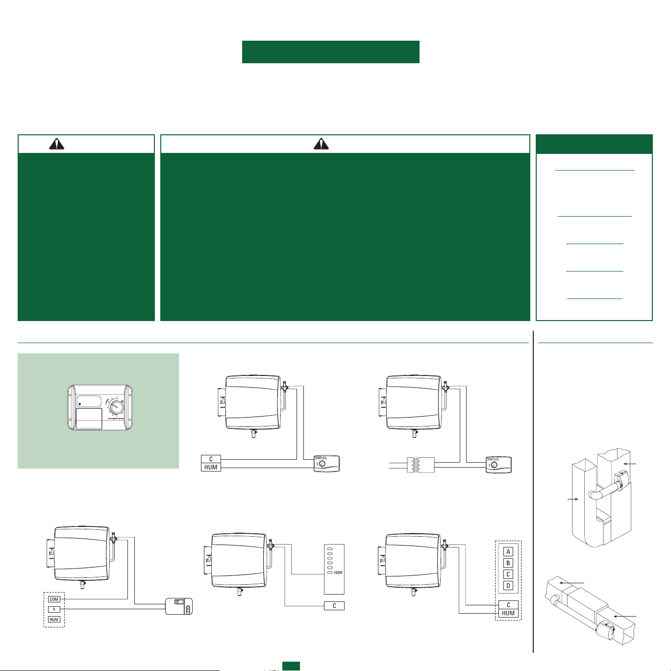
8. In order for humidifier to turn on, the furnace
blower must be operating and the Humidifier Control
must be calling for humidity. The interface between
the humidifier and the furnace to detect blower
operation can be accomplished several different
ways. See wiring diagrams on other side for options.
Do not use furnace blower motor wiring to power
transformer. Damage to equipment may result.
9. Tap into a water supply line with the saddle valve
furnished. See instructions on saddle valve package.
The humidifier will function with cold, hot, softened
or unsoftened water. The use of service hot water
(140°F MAX.) and constant blower operation will
provide maximum evaporative capacity.
When installing humidifier on heat pump
system, humidifier must be supplied with
service hot water.
NOTE: The saddle valve is designed to be
fully opened or closed. Do not use it to
regulate water flow.
10. Connect tubing from the saddle valve to
the inlet side of the solenoid valve using 1⁄4”
O.D. copper tubing (not furnished). DOUBLE
WRENCH TO PREVENT LEAKING!
(See Figure 3)
11. Drain spud is designed to accept 1⁄2” I.D.
plastic hose (not furnished). Run drain line
from drain spud to floor drain. CAUTION: If
hose clamp is used, do not over tighten, drain
spud could crack. Make sure drain line has
constant downward slope and is not kinked.
NOTE: Do not sweat or directly attach metal
drain line to fitting. Do not use solvent type
adhesive when connecting plastic drain line,
since damage to fitting could result.
12. Open saddle valve completely and turn
on furnace. Turn up humidifier control so
that humidifier will turn on. Allow humidifier
to run until water is observed coming out of
the drain line. Check to see if humidifier and
saddle valve are watertight. Check operation
to make sure that all electrical components
function properly. Set humidifier control to
level recommended in Owner’s Manual.
NOTE: BEFORE LEAVING THE
JOB SITE, MAKE SURE:
1. Saddle valve is fully open.
2. All plumbing connections are
watertight.
3. Humidifier functions properly.
4. Bypass damper is in proper
position.
7A. MANUAL HUMIDIFIER CONTROL INSTALLATION INSTRUCTIONS:
The Manual Humidifier Control is designed for low voltage service to control
humidification equipment. An increase in relative humidity expands the nylon ribbon
that opens the control switch to stop operation of the humidifier. A decrease in
relative humidity reverses the process and closes the control switch.
GENERAL INSTRUCTIONS
1. Do not attempt to repair or
recalibrate Humidifier Control.
Humidifier Controls requiring
service should be returned to
your distributor.
2. Use Humidifier Control in low
voltage (24 VAC) applications
only. Install 24 VAC wiring to
Humidifier Control as shown in
Wiring Diagrams, opposite side.
3. Make sure no bare wires are
exposed or insulation damaged.
Insulation on wire should extend
to head of screws.
4. Make sure all splices are
mechanically and electrically
secure.
5. To remove dirt or other foreign
matter from nylon ribbon and
control interior, dust lightly with
a fine, soft brush.