Ionizing Blower Maunal
9 10
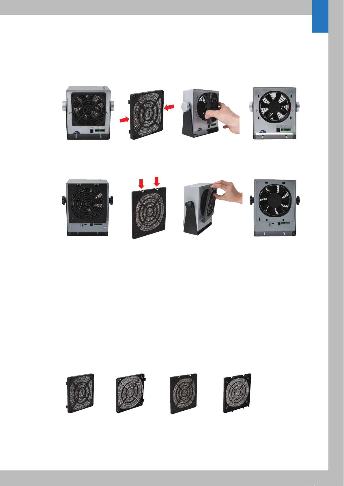
4-4. Emitter Replacement
Cleaning emitter points are varying based on operating environment. Recommended cleaning cycle will be
once in a month or every quarter. Emitter point life cycles are also varying based on operating environment
and performance trade off. Normally, emitter points will requires replace it in every year or second year. If there
is any damage on emitter point, highly recommend replace it. It is very easy to place by user due to pogo pin
and socket design.
5. Ionizer Status
(Model 310 only allow front panel LED indicator)
5-1. LED
Topside LED gives better indication of ionizer operation and alarm status.
5-2. Audio Alarm
Audible buzzer alarm gives better recognition for user or operator
6. Specification
Model 310
Model 310A(S)
Input Voltage 24V DC, 6W (Maximum)
Ion Emission Steady-State DC Technology
Balance < ±20V
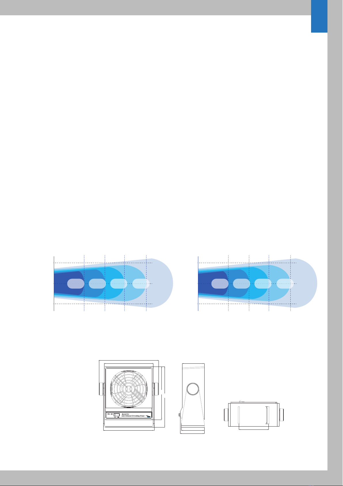
Discharge ±1000V to ±100V less than 2 seconds at 30cm
±1000V to ±100V less than 5 seconds at 60cm
Air ow 59.91 CFM
Emitter Point Tungsten 99.99%
Alarm Function Visual(LED)-HV Power fail
Output Monitoring FMS Interface
Materia Ionizer body- ABS (Gray) Bracket- Aluminum
Operating Environment
Temperature: 15~35℃, Humidity: 35~85% RH
Dimensions 125x135x62mm
(WxHxD) (with bracket 152x154.5x69.5mm)
Weight 507g (with bracket)
Input Voltage 24V DC, 7.2W (Maximum)
Ion Emission Steady-State DC Technology
Balance < ±20V
Discharge ±1000V to ±100V less than 2 seconds at 30cm
±1000V to ±100V less than 5 seconds at 60cm
Air ow 100 CFM
Emitter Point Tungsten 99.99%
Alarm Function Visual(LED), Audio(Buzzer) / HV Power fail
Output Monitoring FMS Interface
Material Ionizer body- ABS (UV Silver pearl coating)
Filter cover- ABS (Black) Bracket- Aluminum
Operating Environment Temperature : 15~35℃, Humidity : 35~85% RH
Dimensions(WxHxD) 125x135x69.5mm (with bracket 152x154.5x69.5mm)
Weight 571g (with bracket)