Core A001 User manual


2
Le informazioni contenute in questo documento sono state attentamente redatte e
controllate. Tuttavia non è assunta alcuna responsabilità per eventuali inesattezze.
Tutti i diritti sono riservati e questo documento non può essere copiato, fotocopiato,
riprodotto per intero o in parte senza previo consenso scritto della D.T.S .
D.T.S. si riserva il diritto di apportare senza preavviso cambiamenti e modifiche
estetiche , funzionali o di design a ciascun proprio prodotto. D.T.S non assume alcuna
responsabilità sull’uso o sull’applicazione dei prodotti o dei circuiti descritti.
The information contained in this publication has been carefully prepared and
checked. However, no responsibility will be taken for any errors. All rights are
reserved and this document cannot be copied, photocopied or reproduced, in part or
completely, without prior written consent from D.T.S.
D.T.S. reserves the right to make any aesthetic, functional or design modifications to
any of its products without prior notice. D.T.S. assumes no responsibility for the use or
application of the products or circuits described herein.
Les informations contenues dans le présent manuel ont été rédigées et contrôlées
avec le plus grand soin. Nous déclinons toutefois toute responsabilité en cas
d'éventuelles inexactitudes. Tous droits réservés. Ce document ne peut être copié,
photocopié ou reproduit, dans sa totalité ou partiellement, sans le consentement
préalable de D.T.S.
D.T.S. se réserve le droit d'apporter toutes modifications et améliorations esthétiques,
fonctionnelles ou de design, sans préavis, à chacun de ses produits. D.T.S. décline
toute responsabilité sur l'utilisation ou sur l'application des produits ou des circuits
décrits.
Las informaciones contenidas en este documento han sido cuidadosamente
redactadas y controladas. Con todo, no se asume ninguna responsabilidad por
eventuales inexactitudes. Todos los derechos han sido reservados y este documento
no puede ser copiado, fotocopiado o reproducido, total o parcialmente, sin previa
autorización escrita de D.T.S.
D.T.S. se reserva el derecho a aportar sin previo aviso cambios y modificaciones de
carácter estético, funcional o de diseño a cada producto suyo. D.T.S. no se asume
responsabilidad de ningún tipo sobre la utilización o sobre la aplicación de los
productos o de los circuitos descritos.

3
INDEX:
1 - SYMBOLS................................................................................................................4
2 - GENERAL WARNING .............................................................................................5
3 - GENERAL WARRANTY CONDITIONS...................................................................5
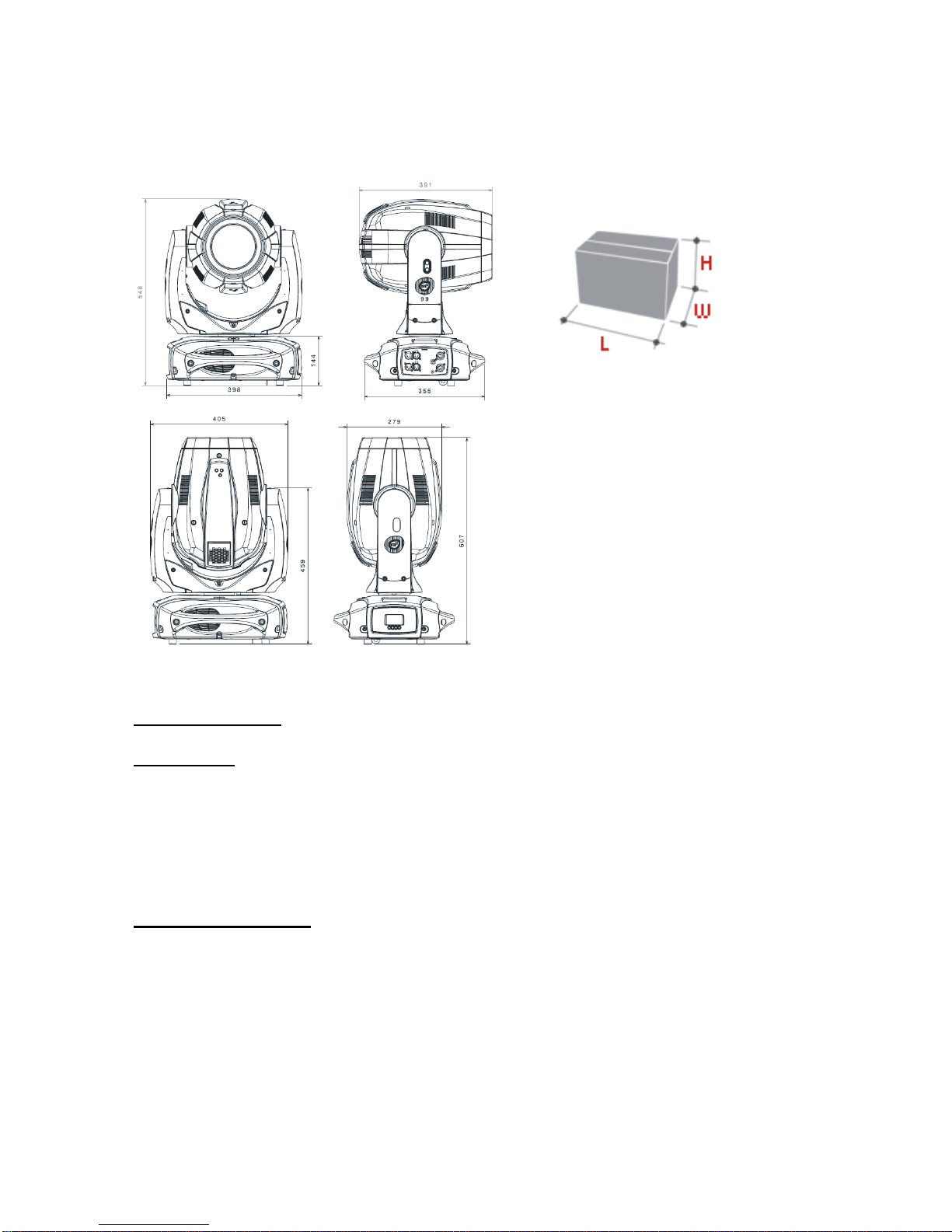
4 - TECHNICAL FEATURES ........................................................................................6
5 - ACCESSORIES .......................................................................................................8
6 - IMPORTANT SAFETY INFORMATION...................................................................9
6.1 Fire prevention......................................................................................................9
6.2 Prevention of electric shock..................................................................................9
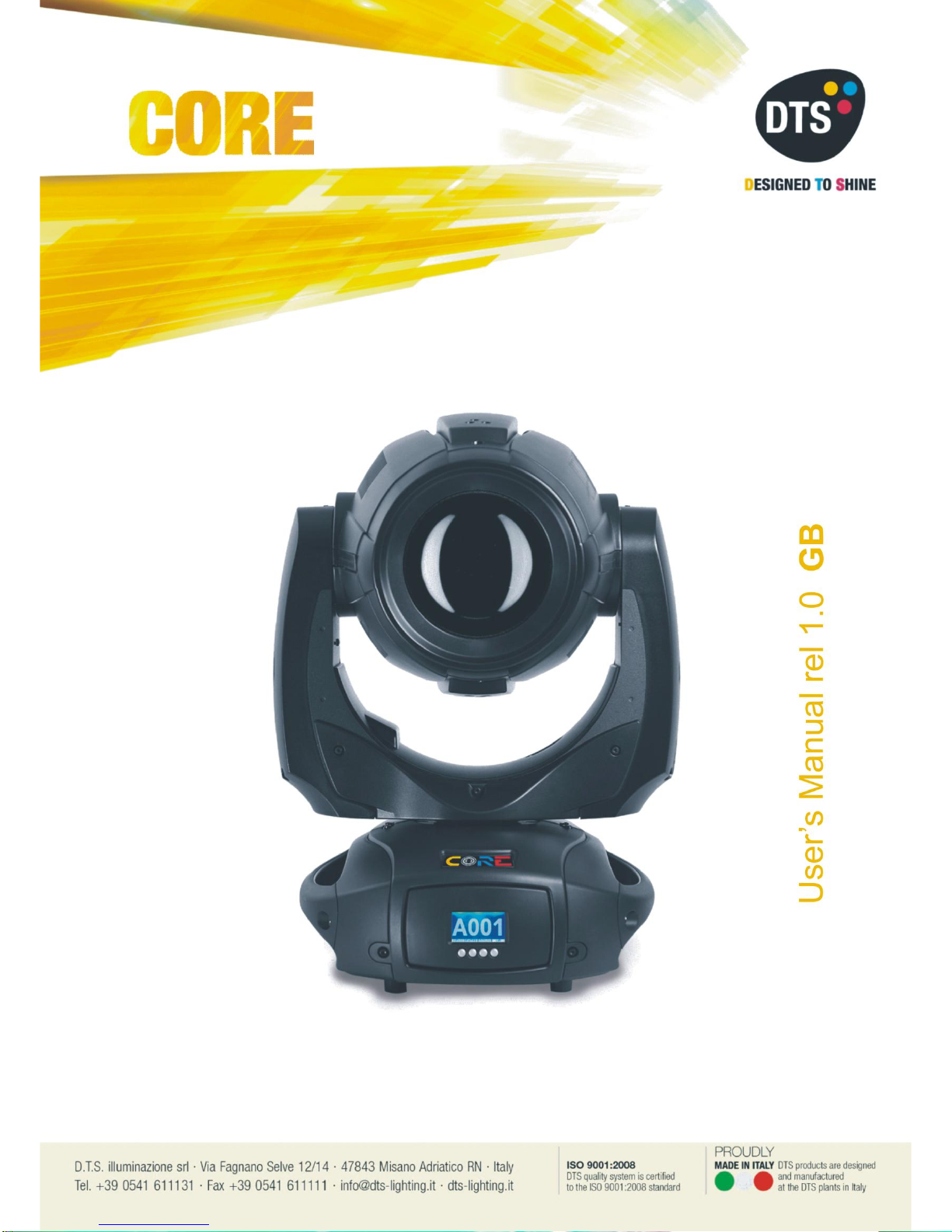
6.3 Protection against ultraviolet radiation..................................................................9
6.4 Safety...................................................................................................................9
6.5 Level of protection against the penetration of solid and liquid objects..................9
6.6 Waste Electrical and Electronic Equipment (WEEE) directive............................10
6.7 Long-life auto-charging buffer battery.................................................................10
7 - PAN / TILT LOCK..................................................................................................11
8 - MOUNTING / REPLACING THE LAMP.................................................................12
9 - VOLTAGE AND FREQUENCY..............................................................................16
10 - INSTALLATION ...................................................................................................16
10.1 Safety cable......................................................................................................17
10.2 Protection against liquids..................................................................................17
10.3 Movement.........................................................................................................17
10.4 Risk of fire ........................................................................................................17
10.5 Forced ventilation.............................................................................................18
10.6 Ambient temperature........................................................................................18
11 - MAINS CONNECTION.........................................................................................18
11.1 Protection.........................................................................................................18
12 - DMX SIGNAL CONNECTION..............................................................................19
12.1 DMX addresses................................................................................................20
12.2 Selecting the DMX address..............................................................................20
13 - FIRMWARE UPDATING......................................................................................20
14 - DISPLAY FUNCTIONS........................................................................................21
15 - ERROR MESSAGES ...........................................................................................25
16 - HIDDEN MENU....................................................................................................27
16.1 Calibration mode ..............................................................................................28
17 - PAN SPEED & TILT SPEED................................................................................29
18 - OPENING THE PROJECTOR HOUSING............................................................30
19 - REMOVING / REPLACING THE ROTATING GOBOS........................................31
20 - PERIODIC CLEANING ........................................................................................32
20.1 Lenses and reflectors .......................................................................................32
20.2 Fans and air passages .....................................................................................32
21 - PERIODIC CONTROLS.......................................................................................32
22 - DMX PROTOCOL................................................................................................33
23 - ROTATING GOBO WHEEL.................................................................................45
24 - FIXED GOBO WHEEL.........................................................................................46
25 - COLOUR WHEEL................................................................................................47

4
1- SYMBOLS
Graphic symbols used on this manual:
THIS SYMBOL INDICATES A HOT SURFACE
THIS SYMBOL INDICATES ELECTRIC
SHOCK RISK
THIS SYMBOL INDICATES GENERAL RISK
THIS SYMBOL MEANS “RADIATION FROM LAMP
CAN CAUSE DAMAGE TO EYES AND SKIN”
THIS SYMBOL MEANS “SUITABLE FOR
INDOOR USE ONLY”
THIS SYMBOL MEANS “SUITABLE FOR
MOUNTING ON NORMALLY FLAMMABLE
SURFACES”
THIS SYMBOL INDICATES THE MINIMUM
DISTANCE FROM THE OBJECTS AND THE
PEOPLE LIT BY THE LIGHT BEAM
THIS SYMBOL MEANS “DO NOT STARE
AT THE OPERATING LIGHT SOURCE”
THIS SYMBOL INDICATES
PHOTOBIOLOGICAL SAFETY
THIS SYMBOL INDICATES THE EUROPEAN
COMMUNITY DIRECTIVE 2012/19/EC ON
WASTE ELECTRICAL AND ELECTRONIC
EQUIPMENT (WEEE)
!
UV

5
2- GENERAL WARNING
Read the instruction contained in this user manual carefully, as they give important
information regarding safety during installation, use and maintenance.
The unit is not for household use and must be installed by a qualified electrician or
experienced person.
Always disconnect the device from the mains before replacing the lamp.
The lamp must be replaced if it has been damaged or deformed by prolonged use or
overheating.
The device must always be equipped with an efficient ground connection.
MINIMUM DISTANCE FROM THE OBJECTS AND THE PEOPLE
The projector needs to positioned so that the objects and the people hit by the
beam of light are at least 15 meters (49,21 ft) from the unit frontal lens.
3- GENERAL WARRANTY CONDITIONS
The unit is guaranteed for 36 months from the date of purchase against manufacturing
material defects.

6
4- TECHNICAL FEATURES
Overview
CORE is a powerful and compact discharge moving head.
SPOT and BEAM all in one with the fastest effects ever seen.
CORE is versatile: thanks to its 440W SIRIUS HRI Lamp, CORE is perfect in a range
of applications, from TV studios to live concerts.
All this in only 22 Kg.
DTS Product Code:
03.MS018.L CORE Black finish
Lamp
Osram SIRIUS HRI 440W (24.000 Lumens)
Colour temperature: 7000K
CRI: 80
Remote lamp On-Off
Average lamp life: 1.500 hrs
Optical group
Improved optical group:
1.530.000 Lux at 5 m
16-bit motorized wide-excursion linear zoom
Beam opening: 2° - 39°
16-bit motorized linear focus
Linear dimmer / shutter / strobe (0,85 flash/sec to 10 flash/sec)
Frost filter
Colour generation
16-colour wheel
Two-tone generation
Dynamic effects
Overlapping wheels for multiple effects:
Customizable rotating gobo wheel (9 gobos)
Fixed gobo wheel (17 gobos + Animation sector + Open)
8-facet 22° rotating prism
Interface / Control / Programming
Auto flip LCD graphic display + 4 soft-keys (control / management / monitoring of the
main parameters)
RDM
Updatable internal operating system
DMX
24 DMX channels (default) or 18 DMX channels

7
Pan & Tilt
Pan 540°: 1.56 sec.; Tilt 270°: 1,5 sec.
Tri-phase stepper motor technology for ultra-fast silent movements
16-bit resolution
Selectable speed ranges
Pan / Tilt lock
Power supply
Full range 100-240Vac 50-60 Hz
Power consumption: 600W with PFC
Power saving mode (the lamp dims to 80% after shutter closure)
Connection
DMX: XLR (3 poles In/Out; 5 poles In/Out) panel connectors
Power supply: PowerCon In/Out panel connectors
Operating ambient temperature
-10° / 40°
Internal safety devices
Overvoltage circuit protection and overtemperature circuit protection
International certifications
Safety: EN 60598-1: 1993
EN 60598-2-17: 1989
A1-A3: 1993
EMC: EN 55015

8
Dimensions
Unit Dimensions (LxWxH) Packaging Dimensions (LxWxH)
405 x 391 x 607 mm 665 x 510 x 525 mm
Weight: 22 Kg Weight: 25 Kg
5- ACCESSORIES
As standard
* 1 x SIRIUS HRI 440W lamp (already installed in the projector) (Code 0505S039)
* 1 x PowerCon male cable connector (Code 0520P014)
* 1 x XLR 5 Pins male cable connector (Code 0508B148)
* 1 x XLR 5 Pins female cable connector (Code 0508B147)
* 2 x Omega clamp with “Fast Lock” connection 1/4 turn (Code 02K00549)
* 1 x User’s manual
Optional (on request)
• Aliscaf clamp for tube diameter 50 mm (max. load 100Kg) (Code 0521A008)
• Safety cable (3mm x 60 cm), max. capacity load 60Kg (Code 0521A010)

9
6- IMPORTANT SAFETY INFORMATION
6.1 Fire prevention:
- CORE uses a SIRIUS HRI 440W lamp.
The use of any other alternative lamp is not recommended and will null and void the
fixture's warranty.
-It is permissible to place the unit on normally flammable surfaces.
Suitable for mounting on normally flammable materials surfaces greater than 200°C
with some combustion time lag.
-Minimum distance from the objects and the people lit by the light beam: 15 m.
-Replace any blown or damaged fuses only with those of identical value (T 8A 250V).
Refer to the wiring diagrams if there is any doubt.
-Connect the projector to mains power via a thermal magnetic circuit breaker.
6.2 Prevention of electric shock:
-High voltage is present inside the unit.
Unplug the unit prior to performing any function which involves touching the inside of
the moving head, including lamp replacement.
-The level of technology inherent in the CORE requires the assistance of specialised
personnel for all servicing. Please refer to an authorised DTS service centre.
-A good earth connection is essential for proper functioning of the projector.
-Never connect the unit without proper earth connection.
-The fixture should be located in places with a good air ventilation.
6.3 Protection against ultraviolet radiation:
-Never turn on the lamp if any of the lenses, filters or plastic covering are damaged.
Their respective shielding functions will only operate efficiently if they are in perfect
working order.
-Never look directly the lamp when it is on.
6.4 Safety:
-Risk Group 2 product according to EN 62471.
CAUTION. Do not look directly into the light output and do not view the light beam with
optical instruments or any device that may concentrate the beam.
May be harmful to the eyes and skin.
-Do not stare at the operating light source.
-The unit is not for household use and must be installed by a qualified electrician or
experienced person.
-The projector should always be installed with bolts, clamps and other tools that are
capable of supporting the weight of the unit.
-Always use a safety cable to sustain the weight of the unit in case of the failure of the
main fixing point.
-The external surface of the unit, at various points, may exceed 70°C. Never handle
the unit until at least 20 minutes have elapsed since the lamp was turned off.
-Always replace the lamp if any physical damage is evident.
-Never install the fixture in an enclosed area lacking sufficient air flow.
The ambient temperature should not exceed 40°C.
UV
!

10
-A hot lamp may explode, so always wait for at least 20 minutes prior to attempting to
replace the lamp.
-Always wear suitable hand protection when handling the lamp.
6.5 Level of protection against the penetration of solid and liquid objects:
-The projector is classified as an ordinary appliance and its protection level against the
penetration of solid and liquid objects is IP20.
Suitable for indoor use only.
6.6 Waste Electrical and Electronic Equipment (WEEE) directive:
- The projector, accessories and packaging should be sorted for environmental-friendly
recycling.
For EC countries: according to the European Directive 2012/19/EC for Waste
Electrical and Electronic Equipment and its implementation into national right,
luminaires that are no longer usable must be collected separately and disposed of in
an environmentally correct manner.
!

11
7- PAN / TILT LOCK
When moving or servicing the unit you can apply the Pan and Tilt Lock.
To lock or release the Pan and Tilt refer to the picture below.

12
8- MOUNTING / REPLACING THE LAMP
WARNING
Turn off the lamp, switch off the unit and unplug the
Mains power cable before opening the unit head covers.
Let the projector cool for at least 20 minutes before replacing the lamp.
Wear protective gloves prior to performing the replacement.
REPLACEMENT LAMP (D.T.S. Code 0505S039) :
Osram SIRIUS HRI
Power 440W
Luminous flux 24.000 lm
Colour temperature 7000K
CRI: 80
Rated life 1.500 hours
The use of any other alternative lamp is not recommended and will null and void the
fixture's warranty.
!
!

13
1) Using a flat bladed screwdriver loose the 3 “¼ turn” screws which fix the head
covers on both sides.
2) Lift each cover and unhook its safety wire to access the internal head components.

14
3) Using a phillips screwdriver, loose the marked 4 screws which fix the lamp rear
metal plate and remove it. Unplug the lamp cables from the lamp faston terminals.
4) Remove the lamp fixing plate by loosing the 4 marked screws and pull out the lamp.

15
5) Put in place the new lamp orientated with its faston terminals towards the hole for
lamp cables as showed in the picture.
Re-install the lamp fixing plate with the convex side towards the lamp.
6) Re-connect the lamp cables and re-install the rear metal plate by fixing the 4
screws. Reset the lamp hours/strikes counter in the “LAMP” menu.

16
9- VOLTAGE AND FREQUENCY
CORE operates at 100-240Vac 50-60 Hz.
10- INSTALLATION
The unit is suitable for dry locations only.
CORE may be either floor or ceiling mounted.
For floor mounting installations, CORE is supplied
with four rubber mounting feet on the base.
For ceiling mounted installations, we recommend
the use of appropriate clamps to fix the unit to the
mounting surface.
The supporting structure from which the unit is hung should be capable of bearing the
weight of the unit, as should any clamps used to hang it.
The structure should also be sufficiently rigid so as not to move or shake whilst the
CORE is moving.
Four 1/4 turn Fast Locks connections placed in the base of the unit allow to hang the
CORE by using the two Omega brackets (provided in the box) in conjunction with
fixing clamps for truss (fixing clamps are not included into the unit box).

17
10.1- Safety cable
A safety cable must be securely fixed to the CORE and to the suspension truss in
order to avoid the fixture accidentally falling should the main fixing point fail.
Make sure that the safety cable or chain can bear the weight of the entire unit.
A suitable safety cable (code 0521A010) is available on demand.
You may attach the safety cable to the attachment point (A) located on the base of the
fixture, as showed in the picture below.
10.2 Protection against liquids
The projector contains electric and electronic components which should under no
circumstances come into contact with oil, water or any other liquid.
The proper unit functioning would be compromised should this occur.
10.3- Movement
Pan 540°: 1.56 sec.; Tilt 270°: 1,5 sec.
Do not place any object in the path of the projector’s movement.
10.4- Risk of fire
Each fixture produces heat and must be installed in a well-ventilated place.
It is permissible to place the unit on normally flammable surfaces.
Suitable for mounting on normally flammable materials surfaces greater than 200°C
with some combustion time lag.
Minimum distance from the objects and the people lit by the light beam: 15 m.
!
!

18
10.5- Forced ventilation
You will note, on inspection, that the unit features various air inlets and cooling fans
located on both the base and head of the fixture.
These should, under no circumstances, be blocked or obstructed whilst the projector
is in operation. Doing so could cause the fixture to seriously overheat thereby
compromising its proper operation.
10.6- Ambient temperature
The projector should never be installed in places that lack a constant air flow.
The ambient temperature should not exceed 40°C.
11- MAINS CONNECTION
CORE operates at 100-240Vac 50-60 Hz.
Prior to connecting the unit to your mains supply, ensure that the model in your
possession correctly matches the mains supply available.
For connection purposes, ensure that your plug is capable of supporting 3,5 amps
at 230Vac, or 7,5 amps at 90Vac each unit connected.
Strict adherence to regulatory norms is strongly recommended.
MAINS OUTPUT
100-240Vac 50-60 Hz (16A Max)
Max 4 CORE units @ 230Vac
Max 2 CORE units @ 120Vac
FUSE MAINS INPUT
T 8A 250V 100-240Vac 50-60 Hz
11.1- Protection
The use of a thermal magnetic circuit breaker is recommended for each CORE.
A good earth connection is essential for the correct operation of the projector.
!

19
12- DMX SIGNAL CONNECTION
The unit operates using the digital DMX 512 signal.
Connection between the mixer and the projector or between projectors must be carried
out using a two pair screened ø 0.5 mm cable and a XLR 5 or 3 pins connector.
Ensure that the conductors do not touch each other.
Do not connect the cable ground to the XLR chassy.
The plug housing must be isolated. Connect the mixer signal to the DMX IN projector
plug and connect it to the next projector by connecting the DMX OUT plug on the first
projector to the DMX IN plug of the second one.
This way, all the projectors are cascade connected.
NB. If the display showing the DMX address flashes, then one of the following errors
has occurred:
- DMX signal not present
- DMX address not valid
- DMX reception problem
For Installations where long distance DMX cable connections are needed, we suggest
to use a DMX terminator.
The DMX terminator is a male XLR 3-5 pins connector with a 120 ohm resistor
between pin 2 and 3.
The DMX terminator must be plugged into the last unit (DMX out panel connector) of
the DMX line.
PLACE A 120 OHM RESISTOR BETWEEN PIN 2
AND 3 OF A MALE XRL CONNECTOR AND PLUG IT
INTO THE DMX OUT PANEL CONNECTOR OF THE
LAST UNIT CONNECTED TO THE DMX LINE
1
2
3
5
4
OUT
120 ohm
PIN 3
PIN 2

20
12.1-DMX Addresses
CORE can be used in 2 different DMX modes: 24 DMX control channels (Default) or
18 DMX control channels.
Here below is described the DMX channels addressing for the controller when CORE
is set to 24 and 18 DMX control channels:
24 channels mode (Default)
Projector 1 A001
Projector 2 A025 If you want to select the next projector, just add “24”
Projector 3 A049
….. A….
projector 6 A121
18 channels mode
Projector 1 A001
Projector 2 A019 If you want to select the next projector, just add “18”
Projector 3 A037
….. A….
projector 6 A091
12.2-Selecting the DMX address
1) Press the UP-DOWN key until you reach the required DMX channel. The numbers
on the display will start to flash (but the new DMX address hasn't yet been set).
2) Press ENTER to confirm your selection. The numbers on the display will stop
flashing and the projector is now setted to the new DMX address.
TRICKS:
If you keep pushed the UP or DOWN keys, the channels are calculated more quickly
and you get a faster selection.
13- FIRMWARE UPDATING
Warning:
This procedure requires a base knowledge of computer application.
Please refer to an authorised D.T.S. service centre.
To update the software version of CORE you need:
- D.T.S. RED BOX interface (D.T.S. Code: 03.LA.008)
- USB-DMX Driver for the D.T.S. RED BOX interface
- “D.T.S. Firmware upgrade utility” program installed on the PC
- Latest software release available for CORE unit
Updating the software version.
Please follow the procedure below to perform the update:
1. Install the D.T.S. RED BOX USB-DMX driver on the PC you will use to update the
unit software.
2. Connect the D.T.S. RED BOX interface to the PC by using a USB cable.
3. Connect the D.T.S. RED BOX interface to the fixture by using a DMX cable.
4. Send the new software version into the unit by using “D.T.S. Firmware upgrade
utility” program.
Table of contents