CORNING OptiTect SRP 000-245 User manual

003-737, Issue 4
STANDARD RECOMMENDED PROCEDURE 003-737 | ISSUE 4 | MAY 2015 | PAGE 1 OF 25
OptiTect®Indoor Local
Convergence Point
Enclosure
related literature | Search www.corning.com/opcomm. Click on “Resources.”
SRP 000-245 Instruction, Splitter Modules
EVO-707-EN Product Specications for OptiTect™ Indoor MDU Local Convergence Cabinet
Table of Contents
1. General .................................................................... 2
1.1 Use and Application ...................................................... 2
1.2 Planning ............................................................... 3
2. Materials and Tools Required ................................................... 4
2.1 Materials ............................................................... 4
2.2 Tools .................................................................. 4
2.3 Auxiliary Equipment ...................................................... 4
3. Components and Shipping Container Contents ..................................... 4
4. Storage and Transportation ..................................................... 6
5. Unpackaging the Enclosure and Components ...................................... 6
6. Installing the Enclosure ........................................................ 7
6.1 Mount the Enclosure on a Wall .............................................. 7
6.2 Mount the Enclosure into a Rack ............................................ 8
6.3 Mount the Enclosure on the Floor............................................ 8
7. Accessing the Enclosure ...................................................... 10
8. Grounding the Enclosure...................................................... 10
9. Managing Fiber ..............................................................11
9.1 Field-installed Unconnectorized Feeder and Distribution Cable Option ...............11
9.2 Preinstalled Connectorized Feeder And Distribution Cable Option ..................11
10. Installing Unconnectorized Cable ................................................11
10.1 Feed Cable into Enclosure ................................................ 12
10.2 Prepare Cable.......................................................... 14
10.2.1 Install Braided Tubing .............................................. 15
10.2.2 Install Grounding Hardware to Armored Cable ........................... 17
10.2.3 Secure Metallic Strength Members .................................... 17
10.2.4 Install Strain-relief Hardware......................................... 18
10.2.5 Ground Cable .................................................... 19
11. Splicing ................................................................... 19
12. Installing Splitter Modules ..................................................... 21
13. Connecting Splitter Input Fibers to Feeder Cable ................................... 21
14. Connecting Splitter Output Fibers ............................................... 23
14.1 Route Splitter Output Fibers to be Connected Now ............................. 23
14.2 Route and Store Splitter Output Fibers to be Connected Later .................... 23
15. Connector Care and Cleaning .................................................. 24

STANDARD RECOMMENDED PROCEDURE 003-737 | ISSUE 4 | MAY 2015 | PAGE 2 OF 25
1. General
The OptiTect™ GEN III Local Convergence Point Enclosure (LCP) serves as an interface
between a telecommunication provider’s network and individual customer connections. The
enclosure provides mechanical and environmental protection for the splices and connector
interfaces while providing easy access for the service provider. It also provides a management
system for optical ber connectors, and splitter modules and a test access point to verify the
integrity of the network. There are several sizes of enclosures available from a 144-ber version
up to an 864-ber capacity unit.
1.1 Use and Application
The OptiTect GEN III LCP is used in an indoor environment, either mounted on a wall, 23-in
equipment rack or pedestal. The enclosure design allows front access to the bers, connectors,
and splitter modules for management, testing, and maintenance by the craft persons.
The interior is accessible through a hinged front door secured with a single-point pawl latch.
The door can be locked with a 216B tool and padlock. The standard conguration is one
connectorized distribution and one connectorized feeder cable preinstalled and attached to the
internal housings.
144-ber Cabinet 288-ber Cabinet 432-ber Cabinet
Distribution 144 288 432
Feeder Maximum 24 bers
(10 are connectorized)
Maximum 48 bers
(18 are connectorized)
Maximum 48 bers
(28 are connectorized))
Splitter Modules (1x32,
1x16)
3/5 9/18 14/28
Parking (Storage) 96 128 192
Table 1: Cabinet Capacity
• Preconnectorized distribution and feeder cables are routed into the enclosure and
terminated on the back side of the connector adapter elds. The front side of each adapter is
ready to receive the connectorized bers from the splitter modules.
• Splitter modules (purchased separately) are installed into the splitter storage area.
Refer to Table 1 for the maximum number of splitter modules for each size of enclosure.
Preconnectorized output bers from the splitter modules can be connected at the time of
installation in the distribution eld or routed to and stored in a connector storage/parking
panel for connection later.
16. Securing the Enclosure ....................................................... 25
17. Maintenance ............................................................... 25
18. Testing .................................................................... 25
18.1 Provisioning Tests ....................................................... 25
18.2 Troubleshooting Tests.................................................... 25
STANDARD RECOMMENDED PROCEDURE 003-737 | ISSUE 4 | MAY 2015 | PAGE 3 OF 25
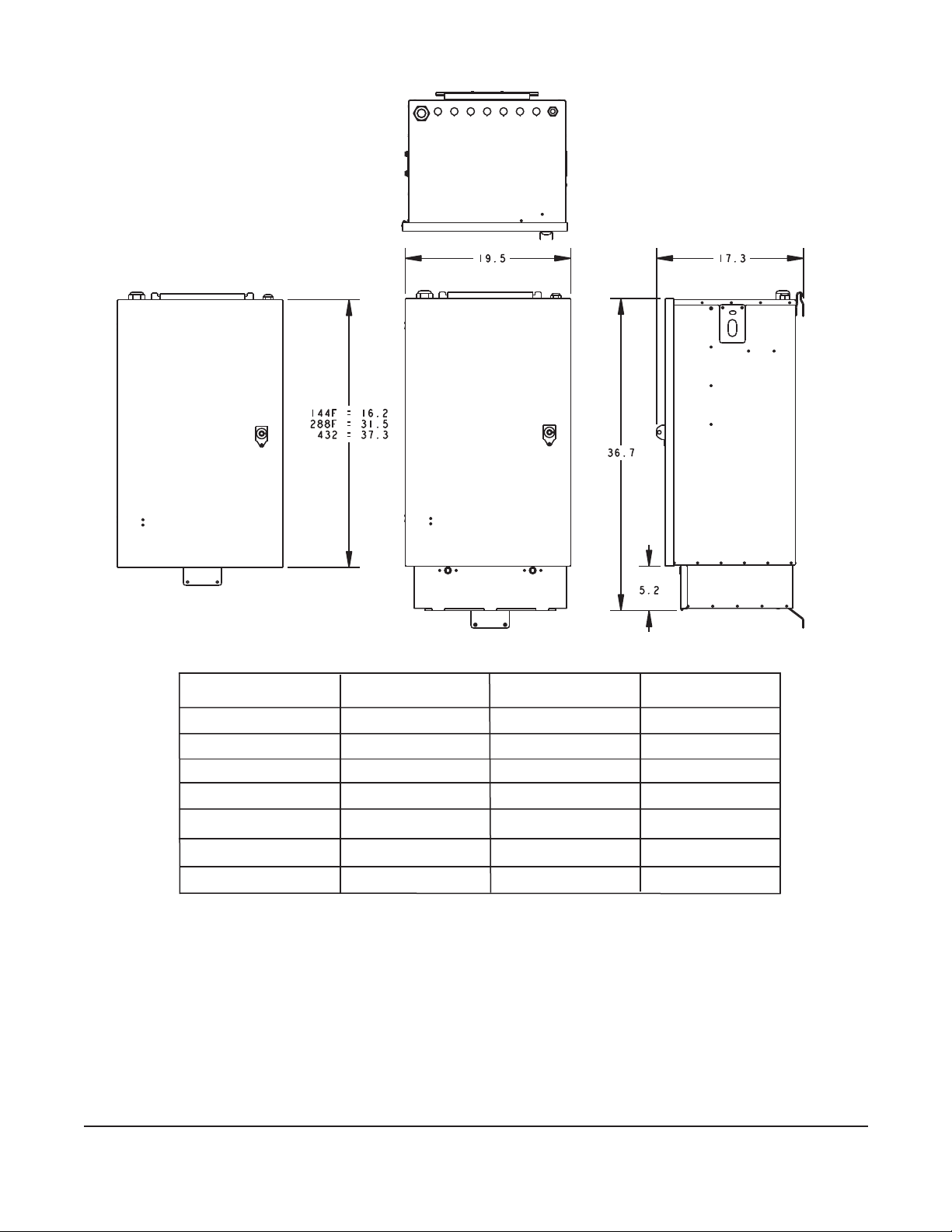
1.2 Planning
Figure 1
Contact a Corning customer care representative to place an order for this product in the
conguration required by your network installation plan.
• The dimensions for each of the enclosure sizes are shown in Figure 1. Ensure that sufcient
space is available at the installation site to accommodate the enclosure. Allow 19 in in front
and 10 in on each side of the enclosure to enable the door to open fully.
• The installing company should obtain rights-of-way from property owners and permits or
other approvals from public authorities prior to installation of the enclosure.
KPA-0887
Weight (Empty)
Depth (inches)
Width (inches)
Height (inches)
Number of Top Ports
Distribution Splice Trays
Feeder Splice Trays
PARAMETER ILCP - 72/144 ILCP - 288 ILCP - 432
6
60 lbs
9
2
1
9
1
70 lbs
19.5
17.3
9
4
1
80 lbs
19.5
17.3
ILCP Cabinet with
Optional Splice Housing
ILCP Cabinet with
Stubbed Cables
46.7 (31.5 w/o splice hsg) 52.5 (37.3 w/o splice hsg)
22.9 (16.2 w/o splice hsg)
19.5
17.3

STANDARD RECOMMENDED PROCEDURE 003-737 | ISSUE 4 | MAY 2015 | PAGE 4 OF 25
• Select an appropriate site per your design plan and follow standard local practices for
installation of the enclosure. The mounting location should be able to withstand the weight of
a fully loaded enclosure.
2. Materials and Tools Required
2.1 Materials
Mounting hardware to attach the enclosure to the wall is not provided. The hardware used is
dependent upon the surface to which the enclosure is being installed; the appropriate hardware
may be purchased from a local hardware store.
2.2 Tools
To install the enclosure, the following tools may be required:
• Hoist or lifting device capable of lifting at least 150 pounds (largest enclosure’s weight,
including packaging)
• Forklift or handtruck
• 216B tool or a 7/16-in nutdriver (for entry into the interior of the enclosure)
• Crescent wrench
• 9/16-in nut driver or socket
• 3/4-in nut driver or socket
• Phillips-head screwdriver
• Dry-process connector cleaning supplies
Depending upon the ber and splicing congurations required for your application, the following
tools may be required to install the enclosure:
• Drill and drill bits
• Lint-free wipes
• Appropriate hardware (if wall mounting) for the wall-mount surface material
• Isopropyl alcohol
• Flat-tipped screwdriver
• Fiber stripping tools
• Splicing equipment and supplies
2.3 Auxiliary Equipment
There is no auxiliary equipment required to install the enclosure. If the enclosure is not full
to capacity, additional products may be installed to expand the customer connections. Refer
to the section, Growth, for details on expanding the capacity. Contact a Corning customer
service representative to order additional products in the conguration required by your network
installation plan.
3. Components and Shipping Container Contents
Figure 2 provides a pictorial description of the enclosure and its components.
• Packing List of Shipping Container Contents:
• (1) OptiTect™ GEN III Local Convergence Point enclosure, prestubbed with distribution
and feeder cables in lengths specied by the customer (other congurations available)
• (1) Installation instruction (SRP 003-737)
• (1) Bag with extra adapter and connector dust caps
• Wallmount kit (p/n 07-000867-001) including mounting brackets and hardware

STANDARD RECOMMENDED PROCEDURE 003-737 | ISSUE 4 | MAY 2015 | PAGE 5 OF 25
• Grounding kit (installed) (p/n FDH-GRND-KIT)
• Rackmount kit (p/n 07-000876-001) to mount in racks with EIA/TIA or WECO hole
spacing
• Feeder and distribution cable installation kit
• Feeder and distribution cable strain-relief kit
• Additional Container Contents for Field-splice Applications:
• Splice trays (number of trays included depends upon conguration)
Figure 2
Cable Entry Ports
Slack Storage
Radius Guides
Panel Latch
Splitter Module
Input Fiber Field
Splice Housing
(Optional)
Removable Door
216B Tool
Pawl Latch
(Optional
Padlock)
Storage / Parking
Panel for Unmated
Connectors
KPA-0732
Lifting Eye
Stored position of lifting eyes
STANDARD RECOMMENDED PROCEDURE 003-737 | ISSUE 4 | MAY 2015 | PAGE 6 OF 25
4. Storage and Transportation
The shipping container and its contents must be stored
indoors in a vertical position in the original packaging. A
forklift or handtruck capable of lifting approximately 150
pounds is required to unload or transport the product in
its shipping container prior to unpacking. Observe all local
safety precautions when moving the container. Do not
double-stack shipping containers.
5. Unpackaging the Enclosure and
Components
Step 1: Place the container near the site prepared
for installation of the enclosure. Remove the
installation instruction.
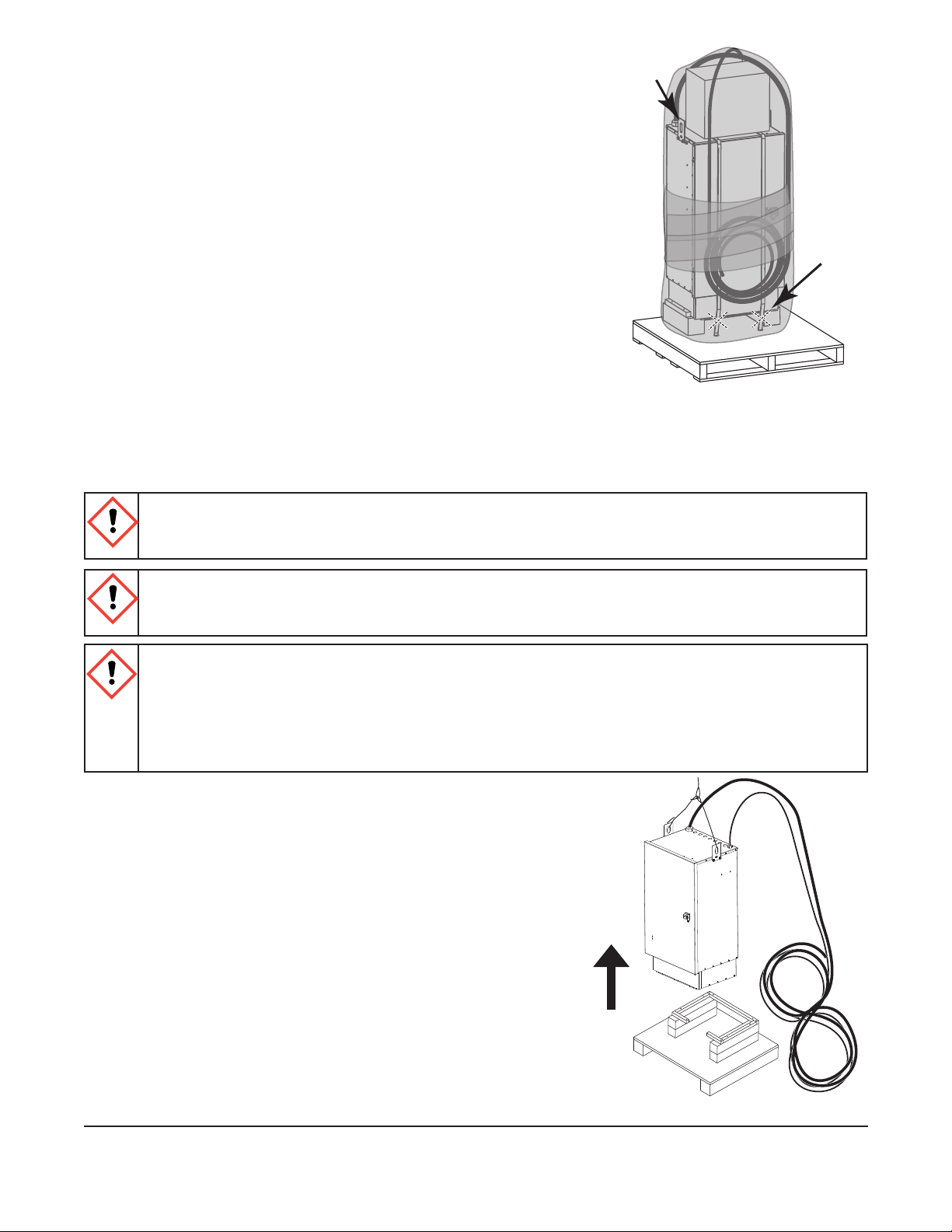
Step 2: Remove the shrinkwrapping from around the
enclosure (Figure 3).
Step 3: Cut the bands holding the enclosure to the pallet.
Step 4: Ensure that a lifting device, such as a hoist or crane, capable of lifting at least 150
pounds (largest enclosure’s weight) is available to lift the enclosure into position.
WARNING: Only certied operators should operate the crane. Ensure that the stabilizers are
extended and rmly positioned before Lifting. Avoid overhead obstructions or power lines
when lifting.
WARNING: The enclosure is heavy and requires two people to maneuver it. Observe all safety
precautions while using Make sure the door is locked in the closed position. Failure to do so
may result in personal injury or damage to the enclosure or cables.
CAUTION: Fiber optic cable is sensitive to excessive pulling, bending, and crushing forces.
Consult the cable specication sheet for the cable you are installing. Do not bend the cable
more sharply than the minimum recommended bend radius. Do not apply more pulling force
to the cable than specied. Do not crush the cable or allow it to kink. Doing so may cause
damage that can alter the transmission characteristics of the cable; the cable may have to be
replaced.
Step 5: If the unit shipped with cables preinstalled, clip
the ties from the cables. Roll out the cables
when removing them from the packaging to
avoid putting twists into the cable. Then loop
the cables in a “Figure-8” pattern next to the
mounting location as shown in Figure 4 before
placing the unit.
Figure 4
KPA-0733
Lifting
Eye
Cut
Bands
Here
Figure 3
KPA-0731
Lift
Cabinet
STANDARD RECOMMENDED PROCEDURE 003-737 | ISSUE 4 | MAY 2015 | PAGE 7 OF 25
6. Installing the Enclosure
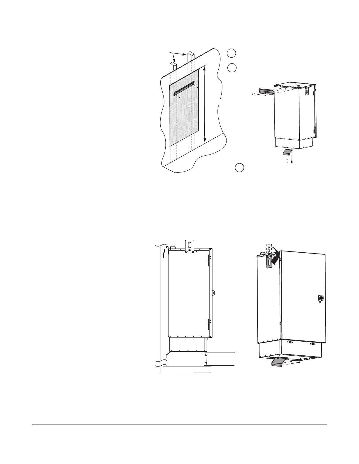
6.1 Mount the Enclosure on a Wall
Step 1: For standard
installation of the
LCP enclosure on a
wall, secure a 4-foot
by 8-foot by 1/2-in
sheet of plywood
to the studs of the
wall in the mounting
location, with the top
edge of the plywood
approximately 80
in above the oor
(Figure 5), at the
height specied in
your standard local
procedures.
Step 2: Using appropriate hardware (not provided), attach the mounting bracket to the
plywood approximately 75 in above the oor. Ensure the bracket is level and secured
to the wall to support the weight of the enclosure.
Step 3: Attach the wallmount mounting brackets to the rear of the enclosure as shown in
Figure 5.
Step 4: Using the hoist or
lifting device, lift
the enclosure and
hook the mounting
bracket over the
bracket on the wall.
IMPORTANT: Lower edge of the
enclosure or splice
chamber should be
located approximately
36 in above the oor.
Step 5: Screw the bottom
bracket into the
plywood and move
the lifting eyes to
their stored position
(Figure 6).
KPA-1783
Attach mounting brackets to cabinet.
Attach mounting bracket to plywood.
Attach plywood to wall.
1
2
3
Floor
Plywood
Wall Studs
Sheetrock
80 inches
Figure 5
KPA-0057
Floor
36 inches
Figure 6

STANDARD RECOMMENDED PROCEDURE 003-737 | ISSUE 4 | MAY 2015 | PAGE 8 OF 25
6.2 Mount the Enclosure into a Rack
Step 1: Install the rack-mount brackets to each
side of the enclosure as shown in
Figure 7.
Step 2: Using a hoist or lifting device, lift the
enclosure, position it within the rack
and secure the enclosure to the rack.
6.3 Mount the Enclosure on the Floor
IMPORTANT: Pedestal must be used when oor
mounting the cabinet. The pedestal may be
attached to the cabinet with or without the
splice housing.
Pedestal Kit (p/n:IFDH-G3-PEDESTAL) comes
with:
• (1) Pedestal Assembly
• (4) #10 Washers (for securing the cabinet to
the pedestal)
• (4) #10-32 Self-locking nuts (for securing the
cabinet to the pedestal)
• (1) Isolation pad (installed between pedestal base and oor)
• (1) Ground wire
Step 1: Determine the cabinet location in your application per the installation plan.
Step 2: Determine the type of installation for oor mounting the pedestal. You will need to
order one of the following kits applicable to your type of installation:
• For mounting by drilling and installing wedge anchors, order p/n FDH-MTNG-KIT-
DRLAN
• For mounting to
precast inserts,
order p/n FDH-
MTNG-KIT-TDIN
• For mounting to
precast studs,
order p/n FDH-
MTNG-KIT-TDST
Step 3: Use the base of
the pedestal as a
mounting template
as shown in Figure
8 to determine
the location of the
mounting holes.
Remove the front
access cover and
mark the holes
shown by the shaded
locations in Figure 8.
KPA-0738
Figure 7
KPA-1343
44.58 cm
(17.55 inch)
24.92 cm
(9.81 inches)
3.81 cm
(1.5 inch)
10.16 cm
(4 inches) 24.26 cm
(9.55 inches)
32.54 cm
(12.81 inches)
Figure 8
STANDARD RECOMMENDED PROCEDURE 003-737 | ISSUE 4 | MAY 2015 | PAGE 9 OF 25
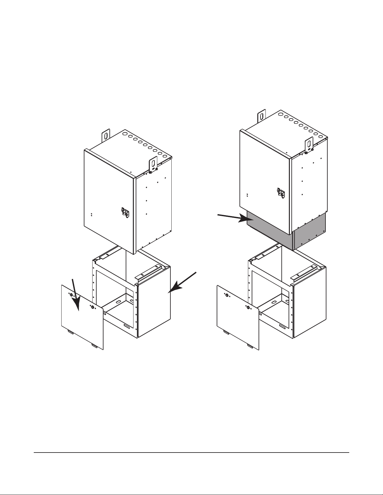
Step 4: Prepare the oor per the installation type and remove excess debris when complete.
Step 5: Position the isolation pad between the pedestal and the oor and secure the
pedestal to the oor (Figure 9) using the hardware for your application.
Step 6: Assemble the cabinet to the pedestal by fully securing the four #10 washers and self-
locking nuts provided.
Step 7: Reattach the front access panel.
Step 8: Replace grounding wire supplied with the cabinet with the grounding wire supplied in
the pedestal kit. It provides additional length allowing the wires to be attached to the
building ground according to standard local codes and practices.
Figure 9
Optional
Splice
Housing
Pedestal
KPA-0740
Front Access
Cover
STANDARD RECOMMENDED PROCEDURE 003-737 | ISSUE 4 | MAY 2015 | PAGE 10 OF 25
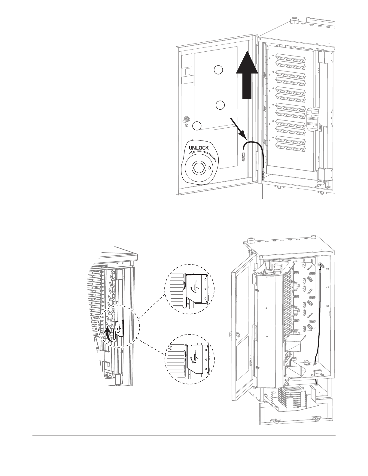
7. Accessing the Enclosure
If the enclosure door is closed, use a
216B tool or a 7/16-in nutdriver on the
latch to open it as shown by the inset in
Figure 10. To facilitate work operations
inside the enclosure, the exterior door
may be removed.
Step 1: Remove ground strap at
the bottom of the door
by removing the two nuts
securing the ground lug to
the door. Replace the two
nuts on the stud to prevent
misplacing them during the
rest of the work operations.
Step 2: After removing the ground
strap, lift the door free of the
hinges. Set the door aside.
Step 3: When work operations are
complete, reverse these
steps to replace the door
and ground strap.
8. Grounding the Enclosure
Step 1: Open the panel door (Figure 11) inside the enclosure to access the ground bar in the
upper right side of the enclosure.
Step 2: Open the splice housing door and pedestal skirt
door, if the enclosure is equipped with these
items. Bring the ground cable up through the
KPA-0739
Remove Strap
1
Unlock Door
2
3
Lift Door
Off Hinges
Figure 10
KPA-0699
OPEN
OPEN
Open
Closed
Figure 11
KPA-0734
Figure 12
This manual suits for next models
1
Table of contents
Other CORNING Enclosure manuals


 user manual")


