CORNING EDGE-10U-PRH User manual

P/N 003-991-AEN
Issue 5
Standard Recommended Procedure 003-991-AEN | Issue 5 | January 2021 | Page 1 of 8
EDGE™ Port Replication Housing
1. Carton Contents
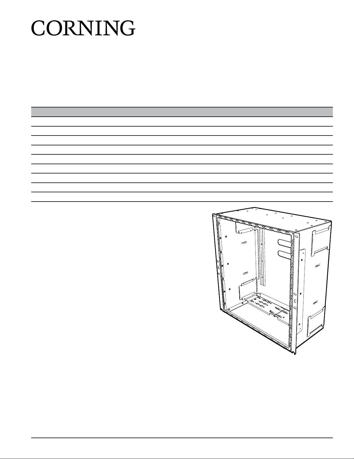
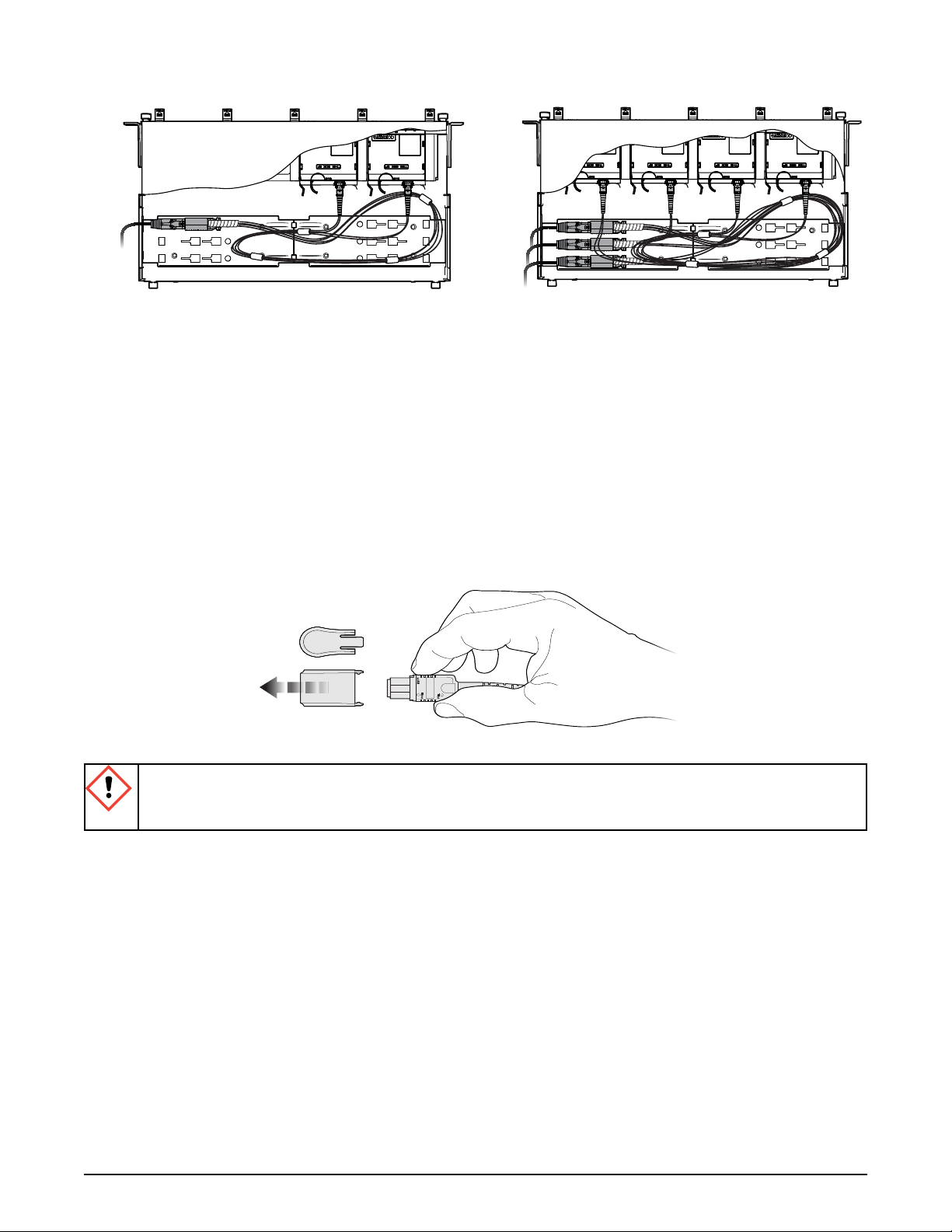
• EDGE™ port replication housing
(EDGE-10U-PRH) (Figure 1)
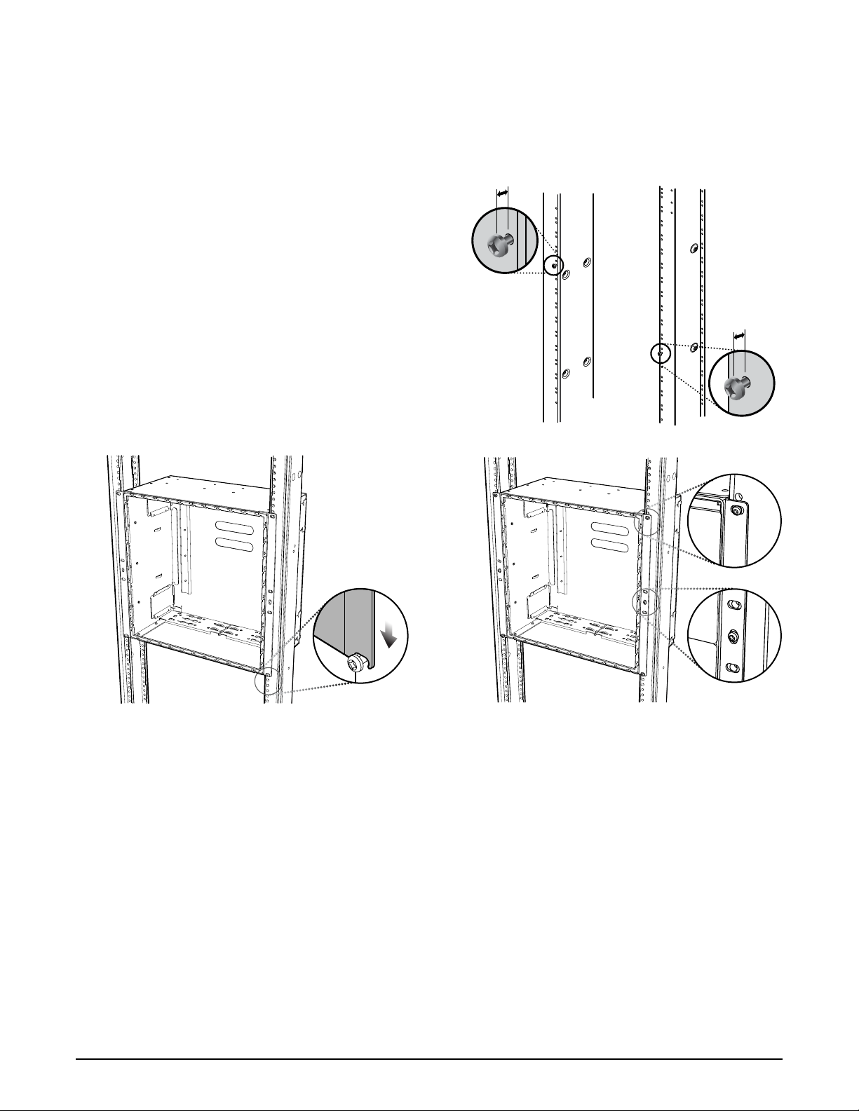
• #12-24 x 0.5-in mounting screws (6)
2. Tools and Materials
2.1 Standard Installation
• Phillips screwdriver
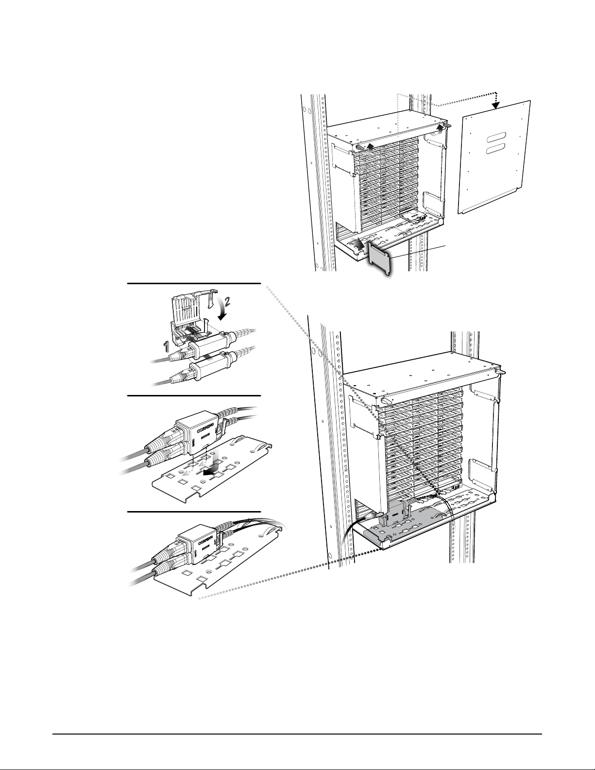
• Double-stack EDGE furcation plug cradles
(quantity one ships with each EDGE trunk)
2.2 Additional Solution Components
2.2.1 EDGE Solution
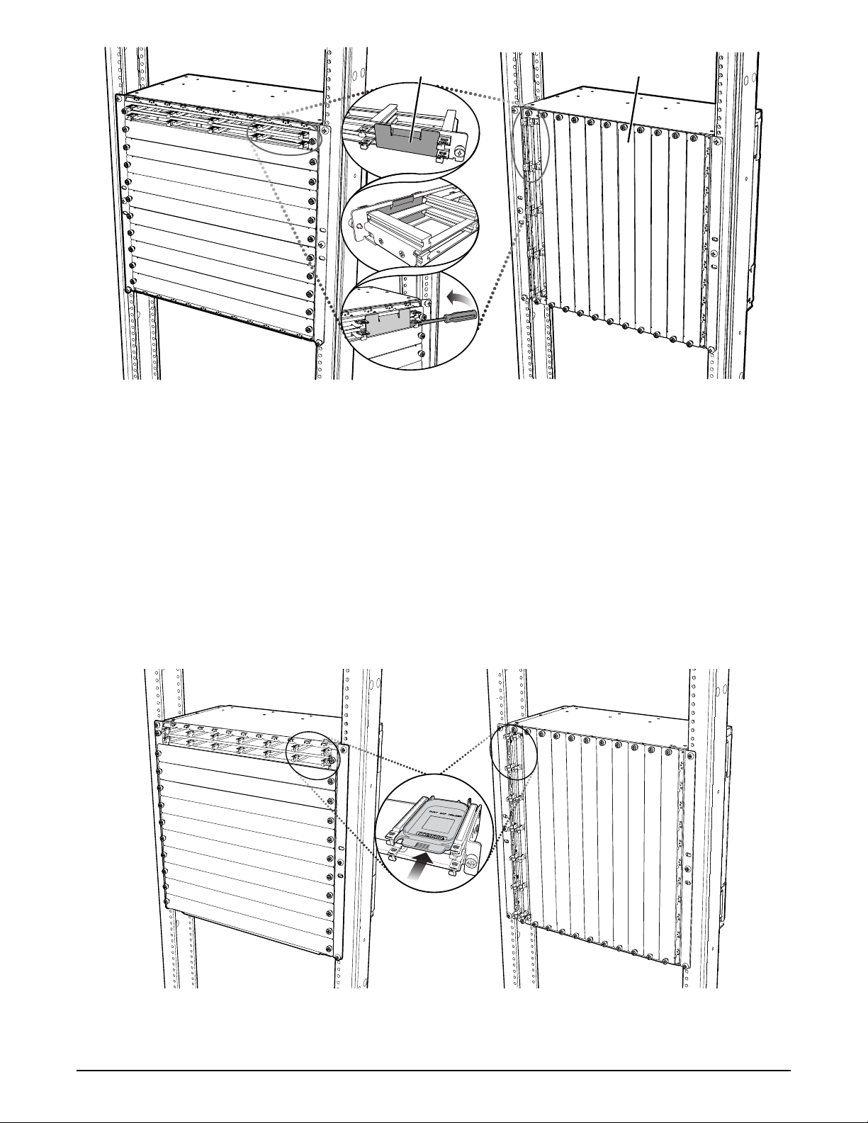
• EDGE panel (EDGE-CP8B-PRH), up to 11 per
housing with up to eight EDGE modules per
panel
• (Optional) Blank panel cover (EDGE-BLNK-PRH)
• (Optional) Blank module cover (EDGE-CPCVR-PRH)
• (Optional) LC adapter panel, aqua (EDGE-CP96-AD-PRH)
• (Optional) LC adapter panel, blue (EDGE-CP96-AE-PRH)
related literature | Search www.corning.com/opcomm. Click on “Resources.”
003-794-AEN EDGE™Solution
003-888-AEN EDGE Solution with 1U/2U/4U Fixed Trays
000-276-AEN EDGE Secure Solutions FTTD Module
003-825-AEN EDGE and EDGE8®Fiber Zone Boxes
003-892-AEN EDGE and EDGE8 Solution Single Module Housing
003-1049-AEN EDGE Solution Single Module Housing for Splicing
000-274-AEN EDGE Splice Cassette EDGE Field-Terminated Cassette
003-885-AEN EDGE Solution Modules in an Enhanced Management Frame
006-407-QSG-AEN Field Tool for MTP®PRO Connectors Quick Start Guide
TPA-4780
Figure 1

Standard Recommended Procedure 003-991-AEN | Issue 5 | January 2021 | Page 2 of 8
2.2.2 EDGE8®Solution
• EDGE8 panel (EDGE8-CP12B-PRH),up to 11 per housing with up to 12 EDGE8 modules per panel
• (Optional) Blank panel cover (EDGE-BLNK-PRH)
• (Optional) Blank-out EDGE8 module (EMOD8-BLANK)
3. Mounting the Housing
Step 1: Install two #12-24 x 0.5-in Phillips screws at desired
height for the bottom of the housing (Figure 2).
Leave a 1/8-in gap behind the screw head.
Step 2: Slide the notch at the bottom of the mounting
bracket on each side of the housing over the screw
heads (Figure 3).
Step 3: Install next two screws in the center obrounds of
the mounting bracket, then into the top obrounds.
Tighten all screws.
4. Install EDGE™or LC Adapter Panel
The panels can be mounted either horizontally or vertically in the housing to mimic the layout of the switch being
replicated.
Step 1: Install the EDGE or LC adapter panel in the orientation desired and secure each end with the captive
fastener.
Step 2: Install blank panels (EDGE-BLNK-PRH), purchased separately, into the EDGE tray over the unused
positions, if desired.
~5mm
(
1
/
4
in)
~5mm
(
1
/
8
in)
TPA-4781
TPA-4783
TPA-4782
Figure 2
Figure 3
Figure 4

Standard Recommended Procedure 003-991-AEN | Issue 5 | January 2021 | Page 3 of 8
NOTE: If installing less than eight modules in the EDGE™tray, a blank module cover (EDGE-CPCVR-PRH),
purchased separately, (shown in the inset in Figure 5) can be installed over two module positions in the
EDGE tray.
5. Install EDGE8®or LC Adapter Panel
The panels can be mounted either horizontally or vertically in the housing to mimic the layout of the switch being
replicated.
Step 1: Install the EDGE8 tray in the orientation desired and secure each end with the captive fastener.
Install blank panels (EDGE-BLNK-PRH) into the EDGE8 tray, purchased
separately, in the unused positions, if desired.
TPA-4784
Module cover Panel cover
TPA-5443
NOTE: If installing less than twelve modules in the EDGE8®tray, a blank-outmodule (EMOD8-BLANK), purchased
separately, (shown in the inset in Figure 6) can be installed into each unused position in the EDGE8 tray.
Figure 5
Figure 6

Standard Recommended Procedure 003-991-AEN | Issue 5 | January 2021 | Page 4 of 8
6. Mount Trunk Cables in the Housing
Step 1: Lift the latches on the rear door of the housing and remove the door (Figure 7).
I
Step 2: Remove the appropriate cable entry
cover by sliding it out the back of the
housing (Figure 7).
Step 3: Open double-stack cradle and press
each trunk cable furcation plug into
cradle (Figure 8).
Step 4: Route cables into housing through
cable entry opening.
Step 5: Insert cradle feet into backplate and
slide into slots to lock in place.
NOTE: Additional backplates are available in the ceiling of the housing for installation of additional cables, or you
may install optional external CDF brackets as described in Section 9.
Step 6: Repeat for all trunk cables and allow connectorized legs to ow out the rear of the housing until ready to
mate in the appropriate module.
TPA-4787
Lower cable
entry cover
TPA-4788
2
Figure 7
Figure 8

Standard Recommended Procedure 003-991-AEN | Issue 5 | January 2021 | Page 5 of 8
7. Trunk Leg Routing
Route the trunk legs wthout violating the minimum bend radius. Use provided lances and hook-
and-loop straps to retain the legs inside the housing perimeter.
8. Connecting MTP®Trunk Cable to Rear of Module—Initial Mating
Step 1: Slide the EDGE™module in from the rear of the panel until the latch on the left side of the module
engages in the panel.
Step 2: Remove dust cover from the MTP®adapter. Also remove the MTP connector dust cap by pulling on the
dust cap while holding the connector body. For the initial mating, do not clean or scope connectors.
Corning®CleanAdvantage™connectors are shipped with an optimized dust cap to maintain cleanliness
for the rst use.
TPA-4790 TPA-4791
Figure 10
Figure 9
TPA-6720
CAUTION: Scoping Corning CleanAdvantage connectors increases the risk of adding contamination to
the system. CleanAdvantage technology is designed for mating connectors without cleaning or scoping
before the initial installation.

Standard Recommended Procedure 003-991-AEN | Issue 5 | January 2021 | Page 6 of 8
Step 3: Mate the MTP connector into the adapter at the rear of the module.
NOTE: When using the panel, you will install MTP trunks into the EDGE™ or EDGE8®modules. Figure 11 shows the
EDGE modules MTP mating; EDGE8 modules are installed in the same manner.
9. (OPTIONAL) Install CDF Bracket
An optional CDF bracket may be installed external to the housing on the frame to provide additional cable trunk
installation positions. It supports incoming cable installation from the top or bottom of the frame into the housing.
The bracket is available in three sizes:
• EDGE-CDF-RJ04-BKT — 4-position furcation trunk holder
• EDGE-CDF-RJ08-BKT — 8-position furcation trunk holder
• EDGE-CDF-RJ12-BKT — 12-position furcation trunk holder
Step 1: Position CDF bracket for optimized leg reach and routing.
Step 2: Install bracket using two 12-24 screws (Figure 12)). Allow enough clearance when routing trunks from the
bracket into the housing to ensure bend radius is maintained when trunks enter the housing.
Step 3: Insert furcation plug into cradle as seen in Section 6 and mount cradle onto CDF bracket (Figure 8).
Step 4: Remove appropriate cable entry cover as described in Section 6. Then route trunks inside the housing
through the openings and terminate at the back of the module.
TPA-4785-B
TPA-4786
Figure 11

Standard Recommended Procedure 003-991-AEN | Issue 5 | January 2021 | Page 7 of 8
10. Completing Installation
Replace housing rear door (Figure 13) and secure with the latches.
TPA-4792
TPA-4789
Figure 12
Figure 13

Standard Recommended Procedure 003-991-AEN | Issue 5 | January 2021 | Page 8 of 8
11. Connector Care and Cleaning — Post Initial Mating
NOTE: Connector care and cleaning should only be necessary after the initial connector mating during testing and
troubleshooting of the network.
a. Clean connectors and adapters using the recommended cleaning tools or kits for the connector type.
• LC connector and adapter cleaning: use cleaning tool part number CLEANER-PORT-LC
• MTP connector and adapter cleaning: use cleaning tool part number 2104466-01
b. Always keep dust caps on connectors and adapters when not in use.
c. Ensure dust caps are clean before reuse.
d. When troubleshooting, clean the connector before re-mating, especially for test equipment patch cords
(jumpers).
• Be sure to clean both connectors that are being mated.
Corning Optical Communications LLC • 4200 Corning Place • Charlotte, NC 28216 USA
800-743-2675 • FAX: 828-325-5060 • International: +1-828-901-5000 • www.corning.com/opcomm
Corning Optical Communications reserves the right to improve, enhance, and modify the features and specications of Corning Optical Communications products without prior
notication. A complete listing of the trademarks of Corning Optical Communications is available at www.corning.com/opcomm/trademarks. All other trademarks are the properties
of their respective owners. Corning Optical Communications is ISO 9001 certied. ©2014-2016, 2020 Corning Optical Communications. All rights reserved.
of 8
Table of contents
Other CORNING Enclosure manuals
Popular Enclosure manuals by other brands

Teledyne
Teledyne Everywhereyoulook ENC-560 installation guide

Belden
Belden PPC PHB872 Series installation instructions

Strand
Strand Vision.Net 53906-001 quick start guide

Pulsar
Pulsar AWO224 Assembly instruction

L-Acoustics
L-Acoustics ARCS WIDE Product information

Altec Lansing
Altec Lansing 5281W CEILING SPEAKER ACCESSORY manual