1817
FRANÇAIS
Table des matières Spécifications du boîtier
Félicitations !
Félicitations................................................................................................................................................................
Spécificationsduboîtier.......................................................................................................................................
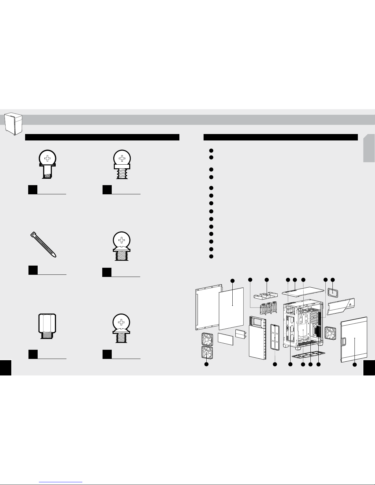
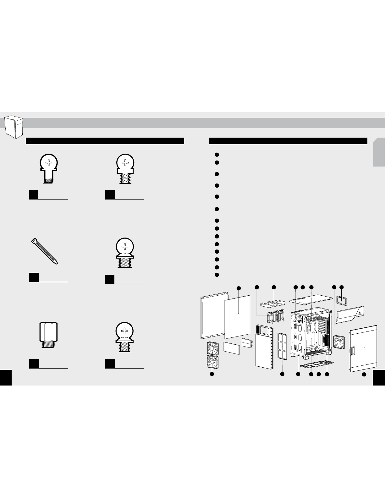
Contenudukitd’accessoires..............................................................................................................................
Attributsduboîtier.................................................................................................................................................
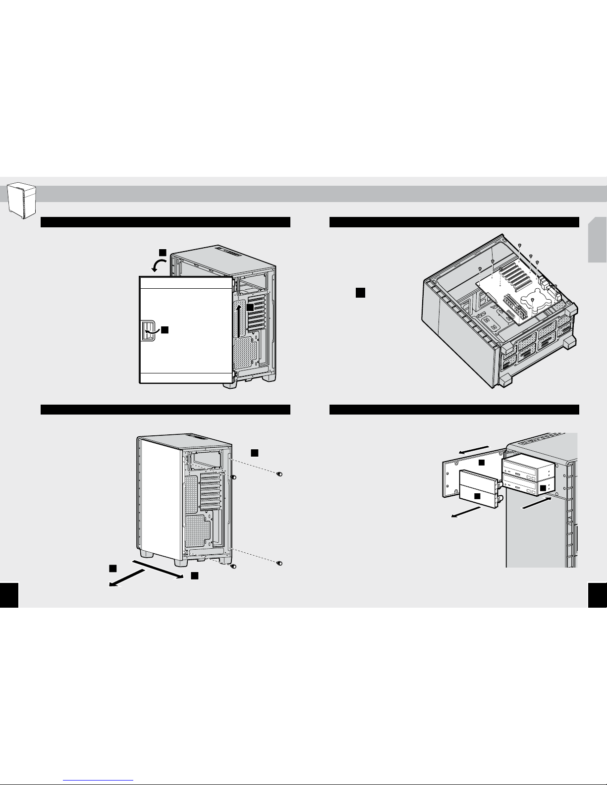
Retraitdespanneauxlatéraux...........................................................................................................................
Installationdelacartemère...............................................................................................................................
Installationdunlecteur............................................................................................................................
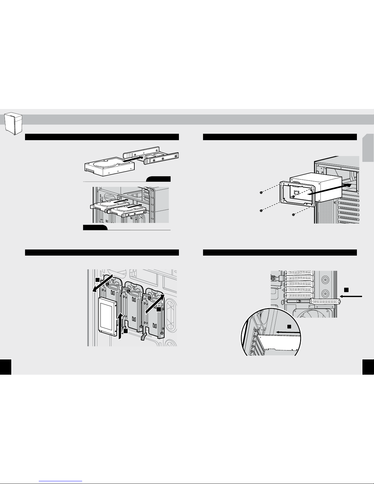
InstallationdesHDD...............................................................................................................................................
InstallationdesSSD................................................................................................................................................
Installationdublocdalimentation..................................................................................................................
InstallationdescartesPCI-EPCI......................................................................................................................
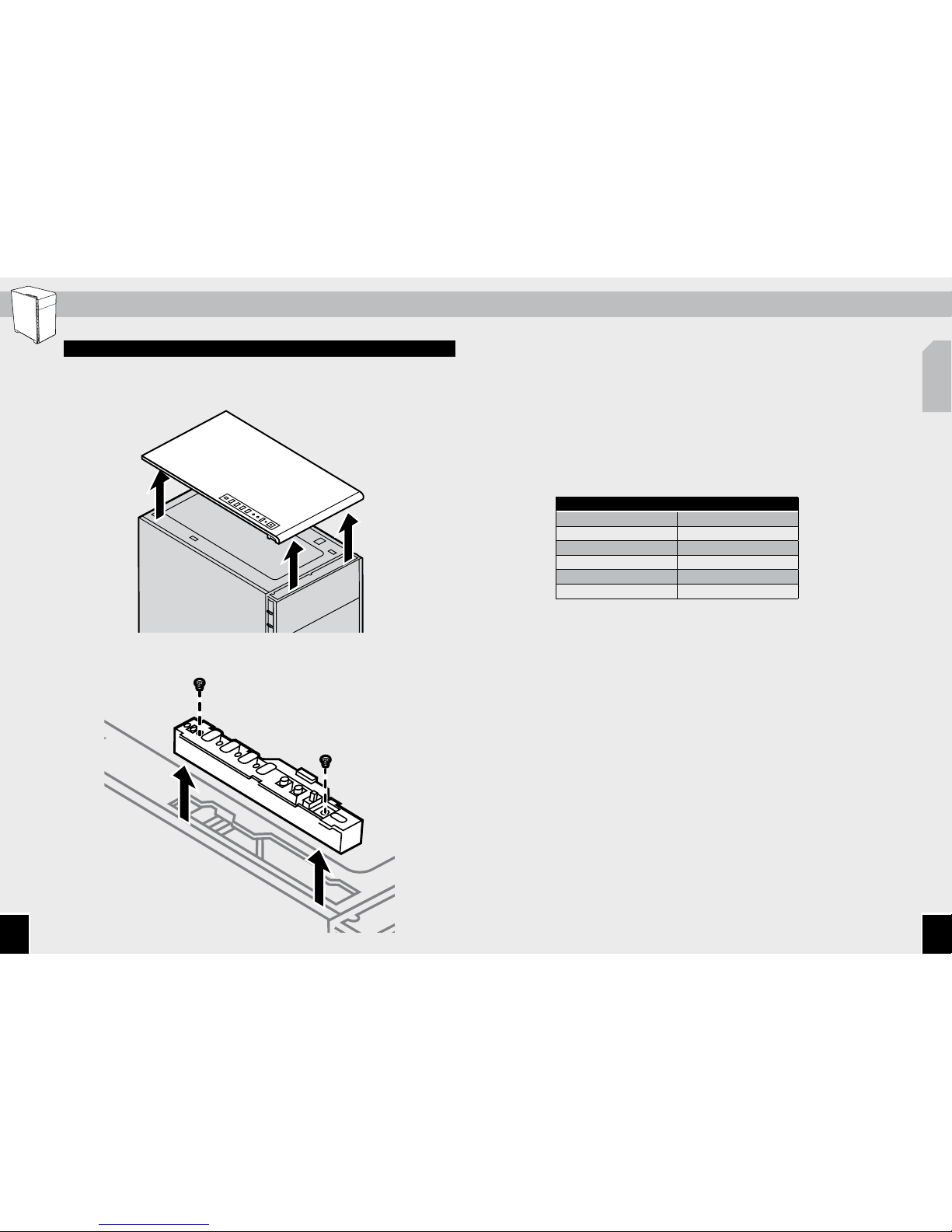
Retraitdespanneauxfrontaletsupérieur....................................................................................................
Nettoyagedesfiltresàpoussière.....................................................................................................................
Raccordementducontrôleurdeventilateur................................................................................................
InstallationdesconnecteursESavant..........................................................................................................
Foireauxquestions..........................................................................................................................................-
Merci d'avoir acheté le boîtier Carbide Series 600.
Longueur ................................................................................................mm
Largeur....................................................................................................mm
Hauteur....................................................................................................mm
Poids...........................................................................................................kg
Longueurmaximaledelacartegraphique ............................. mm
Hauteurmaximaledurefroidisseurduprocesseur .............mm
Longueurmaximaledublocdalimentation...........................mm
Compatibilitéduradiateur
Avant ...........................................................xmmouxmm
Bas................................................................xmmouxmm
Arrière .........................................................xmmouxmm
535mm
454mm
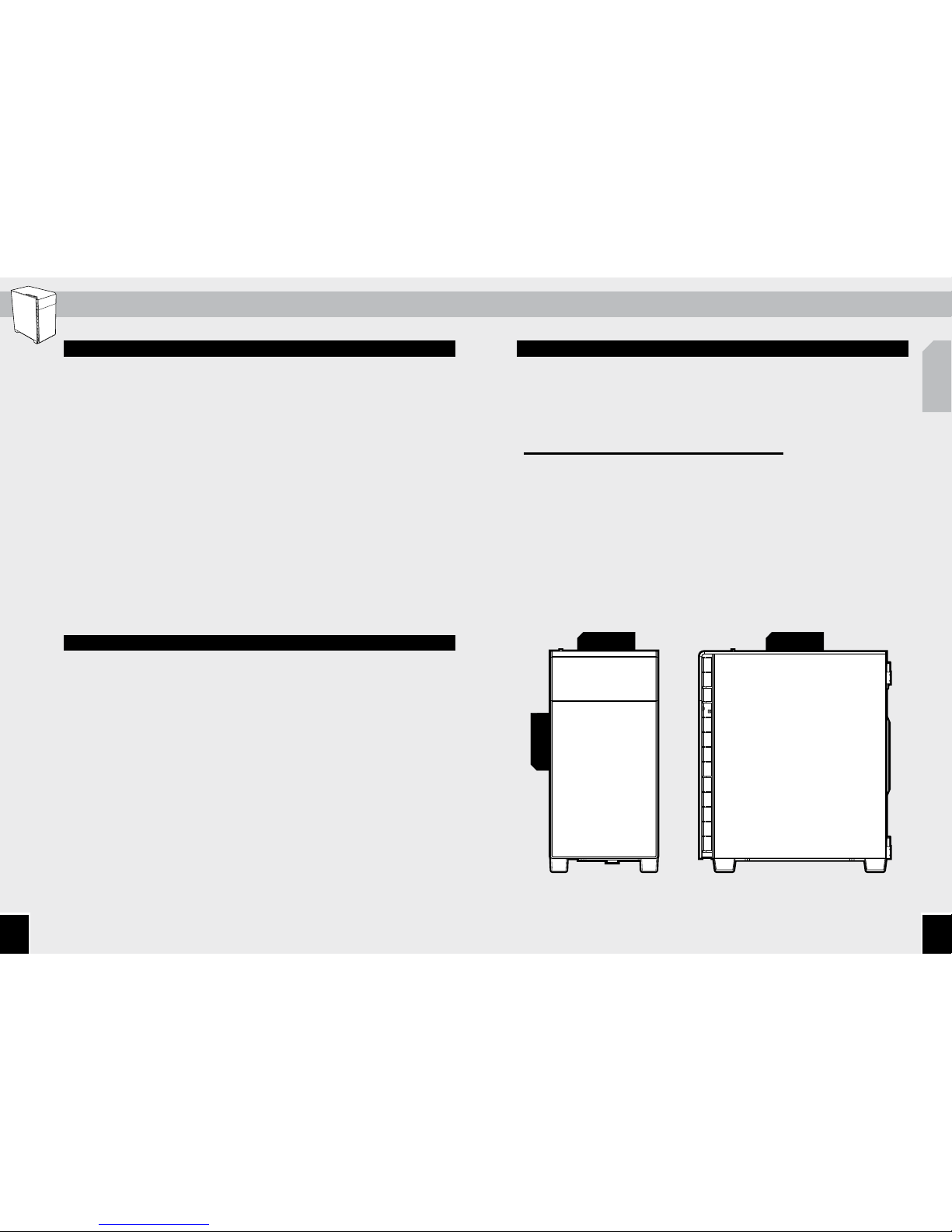
Carbide Series Quiet 600Q
La forme extérieure incurvée et minimaliste du 600Q abrite une disposition ATX
inversée afin de maximiser le flux d'air et de minimiser le bruit. Une trappe dissimule
deux baies pour lecteur de 5,25 pouces, tandis qu'un contrôleur de ventilateur à
trois vitesses vous permet de sélectionner le flux d'air et le profil de performances
adaptés à votre confort. Retourner la carte au format ATX standard nous permet de
fermer le dessus du boîtier 600Q tout en laissant le dessous ouvert. Nous améliorons
ainsi les performances du refroidissement et l'atténuation des sons. Lorsqu'il s'agit
d'assembler votre propre équipement, vous ne devriez pas avoir à choisir entre bruit et
performances. Et notre boîtier 600Q est là pour le prouver.
Carbide Series Clear 600C
La forme extérieure incurvée et minimaliste du 600C abrite une disposition ATX
inversée afin de maximiser le flux d'air et de minimiser le bruit. Une trappe dissimule
deux baies pour lecteur de 5,25 pouces, tandis qu'un contrôleur de ventilateur à trois
vitesses vous permet de sélectionner le flux d'air et le profil de performances adaptés à
votre confort. Inverser la carte au format ATX standard vous permet d'exposer la partie
visuellement la plus intéressante de votre carte graphique – le refroidisseur – plutôt
que de présenter une carte de circuits intégrés sans intérêt. Lorsqu'il s'agit d'assembler
votre propre équipement, le boîtier 600C vous ore un look et des performances
exceptionnels.
260mm