Cosco Fitness X-600 User manual

Attention:
Please read all
instructions carefully
before using the
product.
Contents
Safety Information
Components-Parts
Components-Fixings
Assembly Instructions
Parts List
Model:
X-600
Retain this
manual for
reference
2018-10-24
OWNER’S
MANUAL
Model: X-600
Six Station Home Gym

Contents
Before you Begin
1
Safety Information
2
Components-Fixings
3
Components-Parts
4-5
Assembly Instructions
6-30
Parts List
31-32

Thank you for selecting X-600 Six Station Gym. For your safety and benefit, read this manual
carefully before using the machine. As a manufacturer, we are committed to provide you complete
customer satisfaction. If you have any questions, or find there are missing or damaged parts, we
guarantee you complete satisfaction through direct assistance from our factory. To avoid
unnecessary delays, please call our TOLL-FREE customer service number. Our Customer Service
Agents will provide immediate assistance to you.
Before you Begin
1

This equipment is built for optimum safety,
however we still remind you to read the entire
manual before you assemble or operate the
machine. In particular, note the following safety
precautions:
1. Keep children and animals away from the
equipment at any time. Do not let
unsupervised children and the equipment
stay alone in one room.
2. Only six person at a time should use the
equipment.
3. If the user experiences dizziness, nausea,
chest pain, or other abnormal symptoms,
stop the workout and seek immediate
medical attention.
4. This equipment must be built on a clean
and level surface, and should not be used
near water or outdoors.
5. Keep your hands and feet away from all
moving parts.
6. Always wear appropriate workout clothing
when exercising. Do not wear loose or baggy
clothing, as it may get caught in the
equipment. Wear trainers to protect your feet
while exercising.
7. The equipment must be operated in
accordance with its functions described in
this manual, do not operate other accessories
or functions without recommendation from
the manufacturer in order to avoid any injury.
8. Do not place any sharp objects around the
equipment.
9. Disabled persons should not use the
equipment without a qualified person or
doctor in attendance.
10. Before using the equipment to exercise,
always do stretching exercises as part of a
proper warm up.
11. Select an appropriate weight plate to
exercise according to your physical condition.
It is recommended in the way of step by step.
12. Do not use the equipment when its
function is incomplete.
13. It is suggested to exercise with supervisor
around.
14. This product is suitable for a maximum
user weight of: 120kgs.
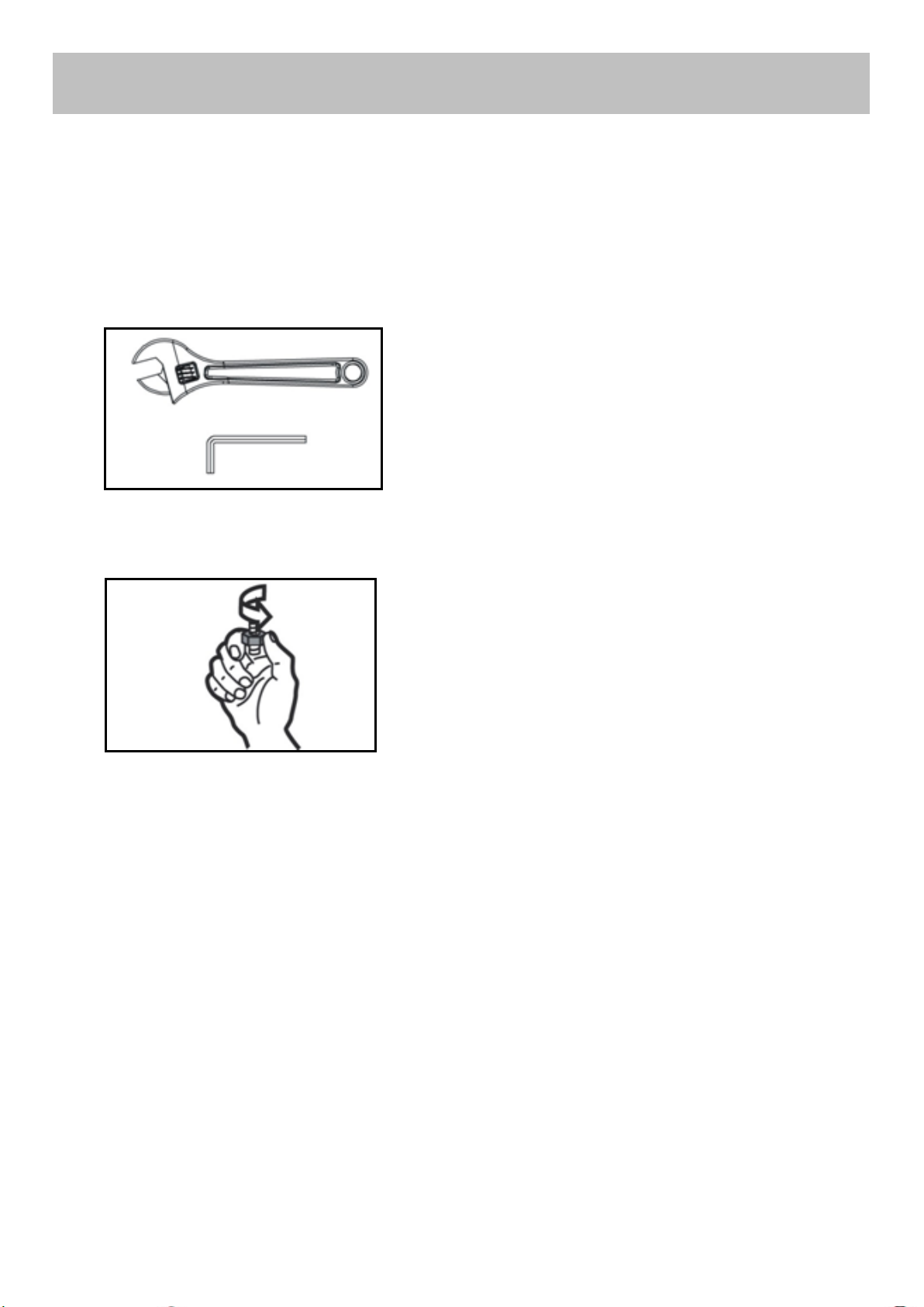
Care and Maintenance
1. Periodically lubricate all the moving parts.
2. Check and tighten all the parts before
using the equipment.
3. Use a damp cloth and mild cleaner to clean
the equipment, any chemical solvent shall not
be used for this purpose.
Rope Tension Adjustment
Adjust the rope system by moving the lower
pulley on the position of pulley support.
1. If the rope tension is too loose, raise the
position of the lower pulley to next higher hole.
2. If the rope tension is too tight, reduce the
position of the lower pulley to next lower hole.
The lower pulley:
Warning: Before beginning any exercise program,
consult your doctor. This is especially important for
persons over the age of 35 or persons with pre-
existing health problems. You must read all
instructions before using any fitness equipment. We
assume no responsibility for personal injury or
property damage sustained by or through the use of
this product.
Please keep this manual.
Safety Information
Important –Please read fully before assembly or use
Warning
2

M6x20 Allen Bolt x 4
M8x18 Allen Bolt x 18
M8x65 Allen Bolt x 8
M10x20 Allen Bolt x 36
M10x45 Allen Bolt x 9
M10x50 Allen Bolt x 9
M10x28 Allen Bolt x 1
M10x70 Allen Bolt x 5
M10x85 Allen Bolt x 3
M10x75 Allen Bolt x 1
M10x80 Allen Bolt x 1
M10x65 Allen Bolt x 2
M10x170 Allen Bolt x 1
M10x70 Carriage Bolt x 23
M10x90 Carriage Bolt x 15
M12x105 Hex Bolt x 2
M12x110 Hex Bolt x 2
Ø12 Washer x 8
Ø10 Washer x
125
Ø8 Washer x 28
Ø6 Washer x 4
M8x70 Allen Bolt x 2
M10 Aircraft Nut x 70
M12 Aircraft Nut x 4
M10 Nut x 8
4# Allen Wrench x 1
5# Allen Wrench x 1
6# Allen Wrench x 2
8# Allen Wrench x 1
M10x25 Allen Bolt x 4
Ø16x154xM10 Axle x 3
Ø16x57xM10 Axle x 2
Components - Fixings
3
161
M10×30 mm Sunk Hex Bolt x 8

Components - Parts (1)
4

Components - Parts (2)
5

Tools: Adjustable spanner x 2
Attention:
It is strongly recommended to assemble the equipment by two or more people, otherwise it may
cause serious injury.
The icon indicates the spanner can be
directly used to tighten and secure
during assembly.
The icon indicates turn the bolt by hand
during assembly, but do not tighten
them so as not to affect next assembly
step.
Assembly Instructions
6

Step 1
1. Sequentially put 1 x Rubber Bumper (62), 1 x Shock Spring (61) and 1 x Rubber Bumper (62) through
the Guide Rod (2), then insert the Guide Rod (2) into the Main Base Frame (1), and secure with 4 x
M10×20mm Allen Bolts (66) and 4 x φ10mm Washers (84).
2. Connect the Flat Bracket (42) to Main base frame (1) using 2 x M10×70mm Carriage bolts (76) and 2 x
M10 Nuts (90). (Note: Please do not tighten the Nuts).
Notes:The Foot □50×50mm (94) and Foot □50×70mm (95) are pre-assembled.
7

Step 2
1. Attach 2 x Brackets (42) to the Side Base Support Frame (35) using 4 x M10×70mm Carriage bolts (76)
and 4 x M10 Nuts (90). (Note: Do not tighten the Nuts )
2. Attach the Side Base Support Frame (35) to the Main base frame (1) using 2 x M10×90mm Carriage
bolts (77), 2 x φ10mm Washers (84) and 2 x M10 Aircraft Nuts (88).
3. Attach the Cross Beam (36) and the 140x51.5mm U-shaped Bracket (3) to the Side Base Support
Frame (35) using 2 x M10×90mm Carriage bolts (77), 2 x φ10mm Washers (84) and 2 x M10 Aircraft
Nuts (88).
Notes: The Foot □50×70mm (95), Bushing φ25×φ22×φ12×10 (138) and Bushing φ25×φ22×φ16×28
(139) are pre-assembled.
8

Step 3
1. Attach the 140x45mm Flat Bracket (42) to the Rear Base Support (5) using 2 x M10×70mm Carriage
bolts (76) and 2 x M10 Nuts (90). (Note: Do not tighten the Nuts)
2. Attach the Main Base Support (4) and Rear Base Support (5) to the Main base frame (1) using 2 x
M10×90mm Carriage bolts (77), 2 x φ10mm Washers (84) and 2 x M10 Aircraft nuts (88).
3. Attach the Foot Pedal (25) to the Main Base Support (4), and secure by inserting the Foot Pedal Axle
(27), cover the two sides with Ø25×1.5 End cap (124).
Notes: The End Cap 50×70×1.5 (98) and φ16mm Sleeve (122) are pre-assembled.
9

Step 4
1. Disassemble the 4 x M10 Nuts (90) on the Side Base Support Frame (35).
2. Attach the Leg Press Block Frame (45) to the Side Base Support Frame(35) using 1 x M10×90mm
Carriage Bolts (77), 3 x φ10 Washers (84) and 3 x M10 Aircraft Nuts (88).
3. Attach the Leg Press Backrest Support (38) to the Side Base Support Frame (35) using 2 x φ10 Washers
(84) and 2 x M10 Aircraft Nuts (88).
4. Attach the Leg Press Seat Pad (39) to the Side Base Support Frame(35) using 1 x M10×90mm Carriage
Bolt (77), 1 x φ10 Washer (84) and 1 x M10 Aircraft Nut (88).
5. Attach the Leg Press Seat Pad (39) and Flat Bracket (42) to the Leg Press Backrest Support (38) using 2 x
M10×70mm Carriage Bolts (76), 2 x φ10 Washers (84) and 2 x M10 Aircraft Nut (88).
Notes: The End Cap 50×70×1.5 (98), End Cap □50×1.5 (99) and Rubber Bumper (108) are pre-
assembled.
10

The label words
on up direction
and face outwards
Front
Step 5
1. Attach the Leg Press Rear Support (48) to the Side Base Support Frame (35) using 1 x Axle
Ø16×154×M10 (81), 2 x Ø10mm Washers (84) and 2 x M10×20mm Allen Bolts (66).
2. Attach the Leg Press Rear Support (48) to the Leg press outer adjust tube (47) using 1 x Axle
Ø16×154×M10 (81), 2 x Ø10mm Washers (84) and 2 x M10×20mm Allen Bolts (66).
3. Attach the Leg Press Front Support (46) to the Leg press outer adjust tube (47) and Side Base Support
Frame (35) using 2 x M12×110mm Hex Bolts (80), 4 x Ø12mm Washers (83) and 4 x M12 Aircraft Nuts
(89).
Notes: The End Cap 25×50 (102), End Cap □60×2 (103), Sleeve 60×45 (106), Bushing
ф25×ф22×ф12×10 (138), Bushing φ25×φ22×φ16×28 (139) and M4×6 Philips Bolt (143) are pre-
assembled.
11

Step 6
1. Attach the Sit Up Base Frame (51) to the Leg Press Backrest Support (38) using 2 x M10×20mm Allen
Bolts (66), 2 x Ø10mm Washers (84) and 1 x M10ר16×57 Axle (82).
2. Attach the Sit Up Board Front Vertical Support (52) to the Sit Up Base Frame (51) using 1 x
M10×75mm (72), 2 x Ø10mm Washers (84) and 1 x M10 Aircraft Nuts (88); adjust the angle of the Sit
Up Base Frame (51) using M8 Lock Knob (127) and Pin φ10×85×M8 (128).
Notes
:
The Foot φ50 (92), End Cap □50×1.5 (99) and Bushing φ25×φ22×φ16×10 (137) are pre-
assembled.
12

Step 7
1. Disassemble the 2 x M10 Nut (90) from the Rear Base Support (5).
2. Attach the Chin up bar upright support (10) to the Rear Base Support (5) using 2 x φ10mm Washers
(84) and 2 x M10 Aircraft Nuts (88).
3. Connect the Cross Beam (36), Front vertical frame (8), Main Base Support (4) with the Push up base
Support (53) using 2 x M12×105mm Hex Bolts (79), 4 x ø12mm Washers (83) and 2 x M12 Aircraft
Nuts (89).
4. Put the Upper frame (9) on the Front vertical frame (8), and then Attach the Upper frame (9) and
140x45mm Flat Bracket (42) to the Front vertical frame (8) using 2 x M10×90mm Carriage bolts (77), 2 x
φ10mm Washers (84) and 2 x M10 Aircraft Nuts (88).
5. Connect the 140x71.5mm U-Shaped Bracket (57) and Chin up bar upright support (10) to the Upper
frame (9) using 2 x M10×70mm Carriage bolts (76), 2 x φ10mm Washers (84) and 2 x M10 Aircraft
Nuts (88).
Notes: The End Cap 50×70×1.5 (98), Small Rubber Bumper (107), Bushing φ25×φ22×φ16×28 (139) and
M6×16 Philips Bolt (142) are pre-assembled.
13

Step 8
1. Put the Guide Rod (2) through the Weight Plates (91), each unit is equipped with 13 pieces of weight
plates.
2. Hammer 2 x Weight Stem Guide Sleeves (20) into the Selector Stem (148) respectively, then insert
the Selector Rod (7) into the Selector Stem (148), and secure the Selector Rod (7) by screwing 2 x
M10×25 Allen Bolts (78) in the Selector Stem (148).
3. The M10×25 Allen Bolts (78) are secured on the top two single holes of the Selector Rod (7).
4. Put the Guide Rod (2) through the Selector Stem (148).
5. Stick the Weight Sticker (159) as shown in the diagram, from top to bottom is 5kg、10kg、
15kg……until 70kg.
14
The direction of
weight plate
inserting holes
The direction of
weight plate
inserting holes
UP

Step 9
1. Attach the L&R Guide Rod Holder (11&12) to the Guild Rod (2) using 4 x M10×20mm Allen Bolts (66)
and 4 x Ø10mm Washers (84).
2. Attach the L&R Guide Rod Holder (11&12) to the Upper frame (9) using 2 x M10×70mm Carriage Bolts
(76), 2 x φ10mm Washers (84) and 2 x M10 Aircraft Nuts (88).
15

Step 10
1. Disassemble the 2 x M10 Nuts (90) from the Main Base Frame (1).
2. Attach the Power Tower Frame (13) to the Main Base Frame (1) using 2 x φ10mm Washers (84) and 2
x M10 Aircraft Nuts (88).
3. Connect the Left Guide Rod Holder (11) to the Power Tower Frame (13) using 2 x M10×70 Carriage
Bolts (76), 2 x φ10mm Washers (84), 2 x M10 Aircraft Nuts (88) and 2 x U-shaped Bracket (44).
4. Attach the Flat Bracket (42) and Foot Support (37) to the Power Tower Frame (13) using 2 x M10×70
Carriage Bolts (76), 2 x φ10mm Washers (84), 2 x M10 Aircraft Nuts (88).
16

Step 11
1. Attach the L&R Dip Arm (14&15) to the Power Tower Frame (13) using 2 x M10×90mm Carriage Bolts
(77), 2 x φ10mm Washers (84) and 2 x M10 Aircraft Nuts (88).
2. Insert 2 x VKR Handle (33) into the L&R Dip Arm (14&15) respectively and secure with 2 x
M10×20mm Allen Bolts (66) and 2 x Ø10mm Washers (84).
Notes: The Hollow Sleeve φ26/□50 (93), Handle Grip ф24×ф34×140 (116), Handle Grip ф24×ф34×190
(119), End Cap ф25 (145), M10×25 Allen Bolt (146) and Serrated washer M10 (147) are pre-assembled.
17

Step 12
1. Connect the Front Press Frame (16) to the Upper Frame (9) using Φ16×154×M10 Axle (81), and
secure with 2 x M10×20mm Allen Bolts (66) and 2 x Ø10mm Washers (84), then attach 2 x ø50×2
End Caps (134) to the Front Press Frame (16).
2. Attach the Butterfly Pulley Bracket (60) to the Front vertical frame (8) using 2 x M10×65 Allen Bolts
(74), 4 x Ø10mm Washers (84) and 2 x M10 Aircraft Nuts (88).
3. Connect the Seat Support Frame (21) to the Main Base Support (4) using 1 x M10×90mm Carriage
Bolt (77), 1 x φ10mm Washer (84) and 1 x M10 Aircraft Nut (88).
4. Connect the Slant Support (22) and Front vertical frame (8) to Flat Bracket (43) using 2 x M10×90mm
Carriage Bolts (77), 2 x φ10mm Washers (84) and 2 x M10 Aircraft Nuts (88).
5. Attach the Slant Support (22) to the Seat Support Frame (21) using 1 x M10×70mm Carriage Bolt
(76), 1 x Ø10mm Washers (84) and 1 x M10 Aircraft Nut (88).
6. Connect the Leg Developer (23) to the Slant Support (22) using Φ16×57×M10 Axle (82), and secure
with 2 x M10×20mm Allen Bolts (66) and 2 x Ø10mm Washers (84).
Notes: The(#96、#104、#105、#109、#162、#139、#141 )are pre-assembled.
18
Table of contents
Other Cosco Fitness Home Gym manuals