CountyLine RBRC402CL User manual

For more information and questions, please contact
Customer Service: 1-844-338-8721
OPERATION AND ASSEMBLY MANUAL
RBRC402CL, RBRC502CL, RBRC602CL
ROTARY CUTTER

2
INTRODUCTION
TO THE OWNER:
Read this manual before operating your implement. Keep this manual handy for reference.
Require all operators to read this manual carefully and become acquainted with all
adjustments and operating procedures before attempting to operate the equipment.
READ THIS MANUAL BEFORE ASSEMBLING OR OPERATING YOUR IMPLEMENT.
REQUIRE ALL OPERATORS TO READ THIS MANUAL.
OBSERVE ALL SAFETY INFORMATION IN THIS MANUAL AND SAFETY DECALS ON THE
IMPLEMENT.
The equipment you have purchased has been carefully engineered and manufactured
to provide dependable and satisfactory use. Like all mechanical products, it will require
cleaning and upkeep. Lubricate the unit as specified. Please observe all safety information
in this manual and safety decals on the equipment. Use only genuine service parts.
Substitute parts will void the warranty and may not meet standards required for safe and
satisfactory operation.
For more information and questions, please contact:
1-844-338-8721
CUSTOMER INFORMATION
Name___________________________________________________
Purchased From__________________________________________
DatePurchased___________________________________________
Model__________________________________________________
Serial #_________________________________________________
PREPARATION CHECKLIST
Verify the following before operating your Rotary Cutter
1. implement is completely assembled.
2. Gearbox is filled with oil and checked for
possible leaks.
3. All fittings are lubricated.
4. All shields in place and in good condition.
5. All fasteners torqued to specifications in
torque chart. (Pg. 36)
6. Check PTO driveline. Make sure it is the
correct length to operate Rotary Cutter
with intended tractor.
7. Check front of input gearbox shaft and make
sure that snap ring is properly installed.
8. Check shear/retaining bolt for proper grade
and installation.
9. All decals in place and legible.
10. Overall condition good (i.e. paint, welds)
11. Operator’s manual has been given to owner
and the owner has been instructed on the
safe and proper use of the Rotary Cutter.

3
INTRODUCTION
GENERAL DESCRIPTION
Your Rotary Cutter has been carefully designed for cutting grass and small brush. This
manual is provided to give you the necessary operation and maintenance instructions
for keeping your rotary tiller in excellent operating condition. Please read this manual
thoroughly. Understand the purpose of the controls and how to use them. Observe all
safety precautions on the machine and as noted throughout this manual. If any assistance
or additional information is needed, contact us at 1-844-338-8721.
NOTICE
All information, illustrations, and specifications in this manual are based on the latest information
available at the time of publication. Because we are always striving to improve our products, the
images could differ slightly from actual equipment. Specifications are subject to change without
notice. We also reserve the right to make changes at any time without notice.
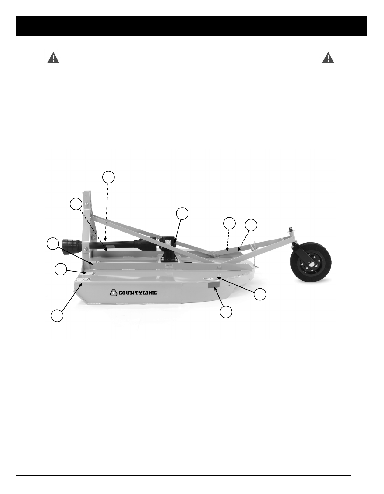
Major components
Gearbox
Tail wheel
Driveline Deck
A-Frame

4
TABLE OF CONTENTS
Safety..............................................................................................................................................................................5
Safety Description and Decals.............................................................................................................................7
Assembly......................................................................................................................................................................13
Attaching....................................................................................................................................................................18
Modify PTO Driveline.............................................................................................................................................. 19
Operation...................................................................................................................................................................22
Lubrication/Maintenance......................................................................................................................................24
Service..........................................................................................................................................................................26
Detaching/Storage................................................................................................................................................ .31
ProductSpecifications............................................................................................................................................32
Parts..............................................................................................................................................................................33
Torque Specifications.............................................................................................................................................36
Trouble Shooting............................................................................................................................................... ......37
Warranty......................................................................................................................................................................38
TABLE OF CONTENTS

5
SAFETY
Rotary Cutter Manufacturer Product Council
Safety is a primary concern in the design, manufacture,
sale, and use of Rotary Cutters. As manufacturers
of Rotary Cutters, we want to conrm to you, our
customers, our concern for safety. We also want to
remind you about the simple, basic, and common sense
rules of safety when using a Rotary Cutter. Failure to
follow these rules can result in severe injury or death to
operators or bystanders.
It is essential that everyone involved in the assembly,
operation, transport, maintenance, and storage of this
equipment be aware, concerned, prudent, and properly
trained in safety. The majority of accidents involve
entanglement on the driveline or thrown objects. These
risks become greater when you do not use proper
shielding specied by the manufacturer.
Our current production machines include, as standard
equipment, guards or shields for drivelines and input
shafts, safety signs and operators manuals. If you have
an older machine which does not have current standard
safety equipment, please contact your dealer about
bringing your machine up to the current level of safety.
Below are some of the most important safety rules to
be understood and followed by anyone who works
with Rotary Cutters:
SAFETY
IMPORTANT SAFETY MESSAGE FOR OWNERS/OPERATORS OF
ROTARY CUTTERS
From members of the Farm Equipment Manufacturers Association
Before operating a Rotary Cutter, an operator must
read and understand all the information in the owner’s
manual and in the safety signs attached to the product.
A person who has not read or understood the owner’s
manual and safety signs is not qualied to operate
the cutter. Accidents occur often on machines that
are loaned or rented to someone who has not read
the owner’s manual and is not familiar with a Rotary
Cutter. If you do not have an owner’s manual or current
production safety signs, contact the manufacturer or
your dealer immediately.
Rotary cutters are designed for one-man operation.
Never operate the cutter with anyone near, or in contact
with, any part of the implement or PTO driveline. Be
sure no one else, including bystanders, is near you when
you operate this product
If operation of a Rotary Cutter around bystanders,
animals, or property that may sustain damage (such as
highway, park, or airport) is absolutely necessary, use
safety guarding recommended by the manufacturer for
thrown object prevention.
Following these simple, basic safety rules, as well
as others identied in the owner’s manual and in
product safety signs, will help minimize the possibility
of accidents and increase your productivity in using
this product. Be careful and make sure that everyone
who operates the cutter knows and understands that
it is a very powerful piece of machinery, and if used
improperly, serious injury or death may result. The nal
responsibility for safety rests with the operator of this
machine.
Phone: 314.878.2304
E-mail: staff@FarmEquip.org
A safety manual for Rotary Cutters is
available through the FEMA ofce.

6
THE BEST SAFETY DEVICE IS AN INFORMED, CAREFUL OPERATOR.
WE ASK YOU TO BE THAT KIND OF OPERATOR.
YOUR SAFETY is our concern. We design and manufacture our implements with this in mind. Our design
can’t eliminate an operator’s careless actions. Hazard control and accident prevention are dependent
upon the awareness, concern, judgment, and proper training of personnel involved in the operation,
transport, maintenance and storage of equipment.
CALIFORNIA PROPOSITION 65
WARNING: Cancer and reproductive harm - www.P65Warnings.ca.gov
Throughout this manual, the term IMPORTANT is used to indicate that failure to observe
procedures can cause damage to equipment. The terms CAUTION, WARNING and DANGER
are used in conjunction with the Safety-Alert Symbol, (a triangle with an exclamation mark),
to indicate the degree of hazard for items of personal safety.
This Safety-Alert Symbol indicates a hazard and means ATTENTION!
BECOME ALERT! YOUR SAFETY IS INVOLVED!
Indicates an imminently hazardous situation that, if not avoided, will
result in death or serious injury.
Indicates a potentially hazardous situation that, if not avoided, could
result in death or serious injury, and includes hazards that are exposed when
guards are removed.
Indicates a potentially hazardous situation that, if not avoided, may
result in minor or moderate injury.
Indicates that failure to observe can cause damage to equipment.
Indicates helpful information.
WARNING
CAUTION
IMPORTANT
NOTE
SAFETY
7
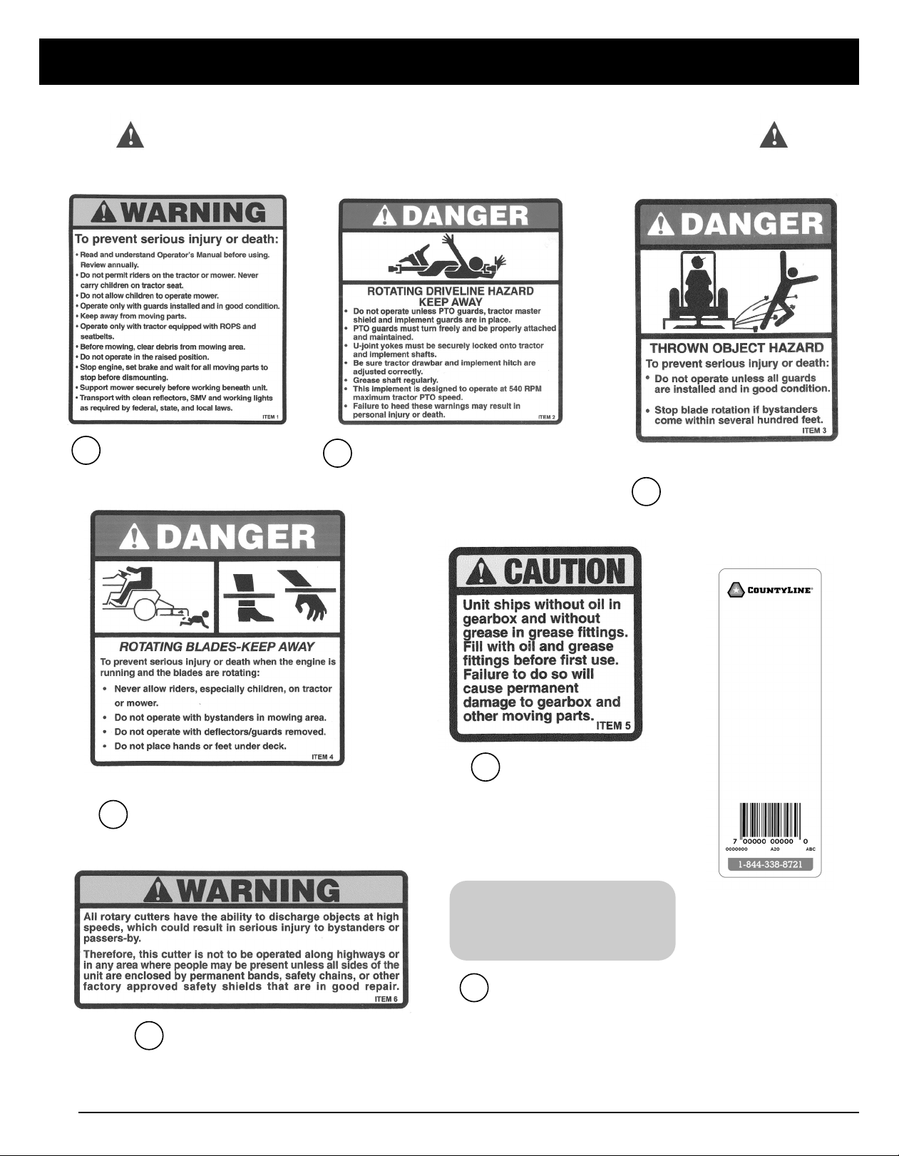
SAFETY AND INSTRUCTION DECALS
4
1
4
6
2
5
7
3
7
3
SAFETY and INSTRUCTIONAL DECALS
ATTENTION! BECOME ALERT! YOUR SAFETY IS INVOLVED!
Replace Immediately if Damaged!
8
1SERIOUS
INJURY
2ROTATING
DRIVELINE THROWN
OBJECT
3
(2 needed)
RED
REFLECTOR
(2 Needed)
7RED REFLECTOR
Warning Label Sheet - Reorder Part #’s
Decals 1-6 (part # RC-DECALS) & Decal 7 (part #
FT4003)
4ROTATING
BLADES
5NEEDS OIL
UPC LABEL
6THROWN
OBJECT
(2 needed)
SAFETY
SAFETY and INSTRUCTIONAL DECALS
ATTENTION! BECOME ALERT! YOUR SAFETY IS INVOLVED!
Replace Immediately if Damaged!

9
SAFETY
SAFETY GUIDELINES
Most accidents can be avoided by a few seconds
of thought and a careful approach to handling
equipment. You, the operator, can avoid many
accidents by observing the following precautions
and insist those working with you follow them too.
If you need assistance or a replacement manual and
safety decals call 1-844-338-8721.
PLEASE READ YOUR TRACTOR/AUV/UTV
(POWER UNIT) MANUAL BEFORE ASSEMBLING
OR OPERATING YOUR IMPLEMENT.
In order to provide a better view, certain
photographs or illustrations in this manual may
show an assembly with a safety shield removed.
However, an implement should never be operated
in this condition. Keep all shields in place. If shield
removal becomes necessary for repairs, replace the
shield prior to use.
Replace any safety decal that is illegible or missing.
Location of such safety decals are indicated in this
manual.
Never use alcoholic beverages or drugs that can
hinder alertness or coordination while operating
the power unit or the implement. Consult your
doctor about operating this machine while taking
prescription medications.
Under no circumstances should children under
the age of 18 be allowed to operate the power
unit or the implement. Do not allow persons to
operate or assemble the implement until they have
read this manual and have developed a thorough
understanding of the safety precautions and how it
works. Review the safety instructions with all users
annually.
This implement can be dangerous to children and
persons unfamiliar with its operation. The operator
should be a responsible, properly trained and
physically able person familiar with farm machinery
and trained in this implement’s operations.
Always use a power unit equipped with a Roll Over
Protective System and seat belts(ROPS). Keep
your seat belt securely fastened because falling
o can result in your death from being run over or
crushed. Always keep a foldable ROPS system in
the “locked up” position at all times.
Never exceed the limits of any piece of machinery,
whether the power unit of the implement. If its
ability to perform a job safely is in question DO
NOT TRY IT.
Do not modify the implement in any way.
Unauthorized modification could result in serious
injury or death and may impair the function and life
of the implement.
In addition to the design of this implement,
including safety signs and safety equipment,
hazard control and accident prevention are
dependent upon the awareness, concern, prudence,
and proper training of personnel involved in the
operation, transport, maintenance and storage of
the implement. Refer also to safety messages and
operation instruction in each of the appropriate
sections of the power unit and implement manuals.
Heed the safety signs axed to both the power
unit and implement.
Follow all safety rules and safety decal information.
Your implement is attached to a power unit. You
must know the controls of your power unit and
how to stop the engine and implement quickly in
an emergency. All operators must be capable to
safely operate the power unit, its attachments, and
all controls.
PREPARATION
Always wear relatively tight and belted clothing
to avoid getting caught in any moving part. Wear
sturdy, rough-soled work shoes and protective
equipment for eyes, hair, hands, ears, and head.
Wear respirator or filter mask when appropriate.
Before using the implement, check all driveline
guards for damage and replace any damaged
DANGER: Failure to follow instructions or
safety rules can result in serious injury or
death.
DANGER: DO NOT allow anyone to operate
the power unit or the implement without
proper instruction.

10
SAFETY
guards. Make sure all guards rotate freely on all
drivelines. Inspect chain or rubber guards before
each use and replace any that are damaged.
Check that all hardware is properly installed.
Always tighten to torque chart specifications unless
instructed otherwise in this manual.
Make sure the implement is properly secured,
adjusted and in good operating condition.
Before using the implement, check and adjust
PTO driveline length as instructed in this manual.
The driveline must not bottom out or pull apart
throughout the full range of the tractor hitch.
Make sure PTO driveline shield safety chain is
attached as shown in this manual and replace if
damaged or broken. Make sure collar slides freely
and is seated firmly in tractor PTO spline groove.
A minimum of 20% of tractor weight must be on
the tractor’s front wheels when implements are
in use. Without this weight, the tractor could tip
over, causing personal injury or death. The weight
may be attained with a loader, front wheel weights,
ballast in tires or front tractor weights. Weigh the
tractor and implement. DO NOT ESTIMATE.
STARTING AND STOPPING
Check the implement master shield over the PTO
(power take o) stub shaft. Make sure it is in good
condition and fastened securely to the power unit.
Purchase a new shield if old shield is damaged or
missing.
All power units that are not equipped with a “live”
power takeo (PTO) must be equipped with an
over-running PTO clutch. These are available
through most farm equipment stores.
The implement is operated from power supplied
from the power unit PTO. Refer to the power unit
manual for PTO engagement and disengagement
instructions.
Understand how to stop the power unit and
implement quickly in case of an emergency.
When engaging the PTO, the engine RPM should
always be at idle speed. Once engaged and ready
to start, raise PTO speed to 540-RPM and maintain
throughout operation.
TRANSPORTATION
Never transport the power unit or the implement
while under the influence of alcohol or drugs.
Always comply with all federal, state and local
laws regarding lighting, marking requirements
and transportation of farm equipment on a public
roadway.
Transport only in daylight or satisfactory artificial
light.
Be aware of overhead utility lines.
Never allow riders on the power unit or implement.
Do not operate PTO during transport.
Watch for hidden hazards on the terrain during
transport.
Do not operate or transport on steep slopes.
Do not stop, start or change directions suddenly on
slopes.
Use extreme care and reduce ground speed on
slopes and rough terrain. When encountering rough
terrain during transport, reduce the power unit
speed to minimize the horizontal movement of the
implement.
Stabilizer bars should be used during transport to
reduce lateral movement of the implement.
Ensure the towing vehicle and trailer are safely
capable of transporting the implement and that
everything is properly secured.
IMPORTANT: DO NOT operate PTO until
driveline length is correct.
NOTE: The addition of an over-running
PTO clutch may change the length of
the PTO driveline required. Be sure to
refer to the instructions on the PTO
driveline installation. Be sure that the
driveline system guarding is adequate.

11
OPERATION
Never operate the power unit or the implement
while under the influence of alcohol or drugs.
Operate only in daylight or satisfactory artificial
light.
Do not allow bystanders in the area when
operating, attaching, removing, assembling or
servicing the power unit or implement.
Never discharge directly toward people, animals or
property.
Ensure the rear-guard assembly is in place to
reduce the possibility of objects being thrown.
This implement is intended for agricultural
applications only. Do not operate within 300 feet of
bystanders or public roads or highways.
Keep hands, feet, hair and clothing away from the
power unit and implement while the power unit
engine is running. Stay clear of all moving parts.
Always sit in the power unit seat when operating
controls or starting engine. Securely fasten seat
belt, place transmission in neutral, engage brake
and ensure all other controls are disengaged before
starting the power unit engine.
DO NOT EXCEED the power unit PTO at 540 RPM.
Look down and to the rear and make sure area
is clear before operating in reverse. REVERSE
OPERATION IS NOT RECOMMENDED.
Be aware that turning the power unit tightly may
cause the implement to come in contact with the
rear wheels of the power unit and cause damage or
injury.
Watch for hidden hazards on the terrain during
operation.
Do not operate on steep slopes.
Do not stop, start or change directions suddenly on
slopes.
Use extreme care and reduce ground speed on
slopes and rough terrain. When encountering rough
terrain, reduce the power unit speed to minimize
the horizontal movement of the implement.
Stop the power unit and equipment immediately
upon striking an obstruction. Turn o engine,
remove key, inspect, and repair any damage before
resuming operation.
MAINTENANCE
Make certain all movement of the power unit
and implement components has stopped before
approaching for service.
Before detaching the power unit from the
implement or performing any service or
maintenance, follow these steps: disengage power
to the power unit, lower the 3-point hitch and all
raised components to the ground, set parking
brake, stop engine, remove key and unfasten
seat belt. Before performing any service or
maintenance, disconnect driveline from tractor
PTO.
Before working underneath the power unit or an
implement, carefully read this manual’s instructions,
disconnect driveline, raise implement, securely
block up all corners with jack stands, and check
stability. Secure blocking prevents an implement
from dropping due to hydraulic leak down,
hydraulic system failures or mechanical component
failures.
Never go underneath an implement (lowered to
the ground or raised) unless it is properly blocked
and secured. Never place any part of the body
underneath the power unit or an implement or
between moveable parts even when the engine
has been turned o. Hydraulic system leak down,
hydraulic system failures, mechanical failures,
or movement of control levers can cause an
implement to drop or rotate unexpectedly and
cause severe injury or death. Follow the power unit
and implement manual for working underneath and
blocking procedures.
Always wear relatively tight and belted clothing to
avoid getting caught in moving parts. Wear sturdy,
rough-soled work shoes and protective equipment
for eyes, hair, hands, ears, and head. When
appropriate wear a respirator or filter mask.
Keep all persons away from you while performing
adjustments, service or maintenance.
SAFETY

12
Frequently check blades/tines/shanks. They should
be sharp, free of nicks and cracks and securely
fastened. Do not handle blades/tines/shanks with
bare hands. Careless or improper handling may
result in serious injury.
Do not modify, alter or permit anyone else to
modify or alter the power unit, the implement or
any of their components in any way, except as
outlined in this manual.
STORAGE
Always use a power unit to position an implement
for storage.
Block the implement securely for storage.
Keep children and bystanders away from storage
area.
OPERATING INSTRUCTIONS
1. Before each use, perform all necessary
maintenance described in the maintenance
section.
2. Read, understand, and follow the safety
information pertaining to training, preparation,
starting and stopping, operation, transportation,
maintenance, and storage at the beginning of
this manual.
SAFETY
WARNING: Never attempt to move
implement by hand.
13
ASSEMBLY
TOOLS REQUIRED
• TIN SNIPS
• SCREWDRIVER
• VICE GRIPS
• RATCHET
• PLIERS
• SOCKETS AND WRENCHES: 9/16”, 3/4”, 15/16”,
7/8”AND 1-5/16”. (Impact wrench is preferred)
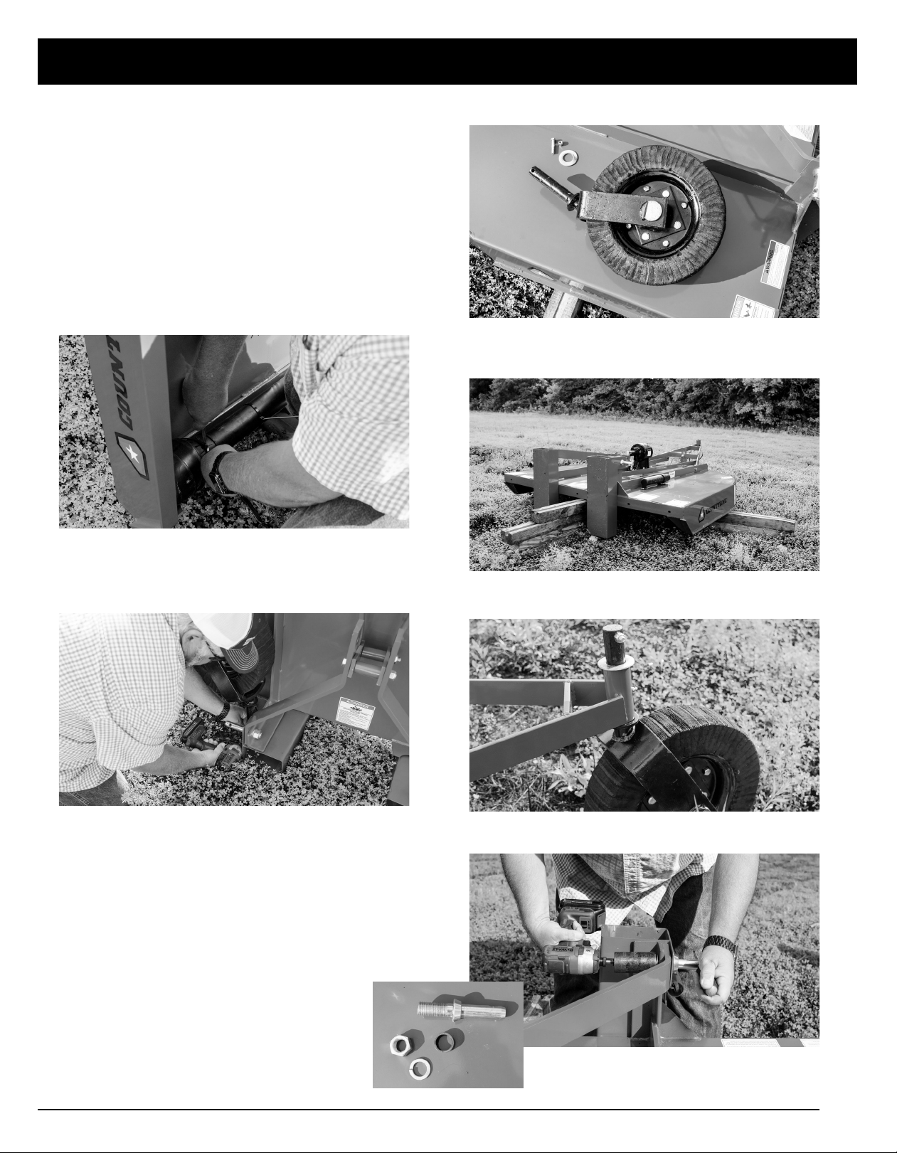
1. Cut the zip ties and remove the PTO Shaft from
the backside of the Rotary Cutter.
2. Remove 3/8” – 16 x 2” bolt and nut from the
tailwheel holder on the shipping boot, using a
9/16” wrench.
DO NOT DISCARD HARDWARE!
3. Remove the tailwheel and 3” washer.
4. Place the Rotary Cutter on a level spot. Block
up the front and back of the Rotary Cutter.
5. Install the tailwheel with 3” washer on top.
Secure with 3/8” – 16 x 2” bolt and nut. Tighten.
6. Using 1-5/16” wrench/socket, remove the CAT I
pins from the shipping boots.

14
ASSEMBLY
7. Once the CAT I pins are removed, lift up on the
cutter to remove from the shipping boots.
8. Line up the holes on the A-frame and re-insert
CAT I pins, bushing, washer and nut. Hand
tighten only.
9. Remove the two zip ties from the tailwheel
assembly and back braces.
10. Raise the lift arms in the upright position, using
the bottom pivot point.
11. Remove nut on one side of the A-frame using
15/16” wrench.
12. Place the backstrap brace on the bolt, as
pictured, using the locknut. Hand tighten.
Repeat for other side.
13. Pull Lift Arms until they are into place.
NOTE: Set aside the CAT 1 pins, bolts,
washers and bushings.
CAUTION: Shipping boots may fall off.
CAUTION: Possible pinch point.

15
ASSEMBLY
14. Go back and tighten the CAT I pins, on both
sides, using a 1-5/16” wrench/socket.
15. Tighten the nuts on the backstraps.
16. Remove the warning label on the gearbox.
17. Remove the shaft boot on the gearbox.
18. Remove the snap ring.
19. Slide the PTO shield back by using a screwdriver
to apply pressure and release the locking collar.
(There will be 3 tabs on the locking collar) Once
the locking collar is released, slide the PTO
shield back.

16
ASSEMBLY
20.Remove the PTO shear bolt.
21. Slide the PTO shaft onto the gearbox shaft.
22. Replace the snap ring.
23. Align the shear bolt holes, install, and tighten
PTO shaft shear bolt.
24. Assembly of your Rotary Cutter is now
complete. Please read the next section of
this manual for filling the gearbox with oil,
lubricating instructions, and sizing your PTO (if
applicable).

17
ASSEMBLY
BEFORE PUTTING YOUR
ROTARY CUTTER INTO
SERVICE
NOTE: Fill the gearbox using EP 85-90W gear
oil. For all grease fittings use TYPE/Grade II tube
grease.
1. Grease the two fittings on the PTO shaft. There
is one on each end of the shaft in the universal
joint.
2. Grease the two fittings on each end of the PTO
Shield.
3. Re-install the PTO shield by sliding the shield
over the universal joint making sure the shield
locks in place.
4. Grease the two fittings in the rear tailwheel
assembly.
5. Using a 7/8” wrench, remove the fill plug
and using a 7mm wrench, remove the drain
plug. Both are located on the backside of the
gearbox.
6. Fill the gearbox with 80W/90 or 85W/140 gear
oil until level with the drain plug. (Holds approx.
1 quart)
7. Replace and tighten both plugs on the gearbox.
IMPORTANT: This Rotary Cutter was shipped
without oil in the gearbox and without
grease in the grease fittings. UNIT MUST BE
SERVICED BEFORE USE.

18
11. Pull back on shield to make sure driveline is
locked.
12. Do not pull back on pin this will release latch.
13. Lower tractor PTO shield, if equipped.
Checking Driveline/Cutter
Clearance
1. Raise cutter slowly and check for clearance be-
tween driveline shield and cutter deck.
2. Check clearance between tractor tires and foot
guards or chain deector.
3. Check to see if hitch height position will provide
clearance desired.
4. Shorten center link or lengthen lift links to
provide clearance. (See your tractor Operator’s
manual.)
5. Raise and lower cutter slowly to check for
binding or interference. Check cutter-to-tractor
driveline telescoping length to ensure that it does
not bottom out. Modify driveline if necessary.
(See MODIFYING PTO DRIVELINE in Assembly
section.)
ATTACHING TO A TRACTOR
1. Back up tractor to cutter with hitch points
approximately in alignment.
2. Engage tractor parking brake and/or place
transmission in Park.
3. Shut o tractor engine and remove key.
4. Remove center link mounting hardware and
hitch pin assemblies at both hitch masts.
5. Install tractor draft links on hitch pins. Secure
with quick lock pins (stored on tractor draft
links.)
6. Align center link with upper hole in cutter mast
straps and install center link mounting hardware.
7. Shut o tractor engine.
8. Raise tractor PTO shield, if equipped.
9. Support driveline, cradling it in your hand.
10. Pull pin back toward cutter. Align splines by
rotating cutter driveline. Push driveline onto
tractor PTO shaft until pin snaps into place.
ATTACHING
DANGER: To avoid bodily injury or machine
damage whenever Rotary Cutter is attached,
put transmission in PARK position and check
the full range of hitch for interference, binding,
or PTO separation. Do not stand between
tractor and Rotary Cutter.
IMPORTANT: Prevent driveline damage from
contact with frame or machine damage from
contact with tractor tires. Raise cutter slowly
and check for interference. If necessary,
shorten center link or lengthen lift links to
provide clearance to full lift height.
NOTE: Final adjustments should be made
before operating cutter. See ADJUSTING
CUTTING HEIGHT AND ANGLE in Operating
the Cutter section. Center link should be
installed in lowest hole at tractor end if there
are multiple holes. Lift height may also be
limited by installing stops on rockshaft control
lever bracket.
NOTE: If the tractor draft links will not open
wide enough to fit over hitch pin assemblies in
their normal configuration the hitch pins can
be inverted so that the draft links can hook up
to the inside.
DANGER: Shut off tractor engine before
attaching PTO driveline. Entanglement in
rotating driveline can cause serious injury or
death.
IMPORTANT: Keep driveline and powershaft
splines clean of paint, dirt and chaff. Apply
grease to tractor PTO shaft before attaching
PTO driveline.
IMPORTANT: PTO driveline may be too long
for some tractor models, causing tractor
transaxle damage. Hold driveline sections
parallel to each other and check for a
minimum of 6 inches overlap.
IMPORTANT: Do not use shielding bell on
driveline to lift driveline into position. Damage
to shielding can occur.

19
Final Inspection and Adjustments
IMPORTANT: PTO driveline may be too long for some tractor models, causing tractor transaxle
damage. Modify driveline if necessary.
Attach Rotary Cutter to tractor and check cutter-to-tractor driveline telescoping length
clearance.
(See MAINTENANCE BEFORE EACH USE in Lubrication and Maintenance section.)
• Modify PTO Driveline (If Necessary)
1. To adjust the length, hold the half-shafts
next to each other in the shortest working
position and mark them.
2. Shorten inner and outer guard tubes
equally.
3. Shorten inner and outer sliding profiles by
the same length as the guard tubes.
4. Round o all sharp edges and remove burrs.
Grease sliding profiles. No other changes
may be made to PTO drive shaft and guard.
5. Chains must be fitted so as to allow
sucient articulation of the shaft in all working
positions.
6. The PTO drive shaft must not be suspended
from the chains!
MODIFY PTO DRIVELINE
MODIFYING PTO
20
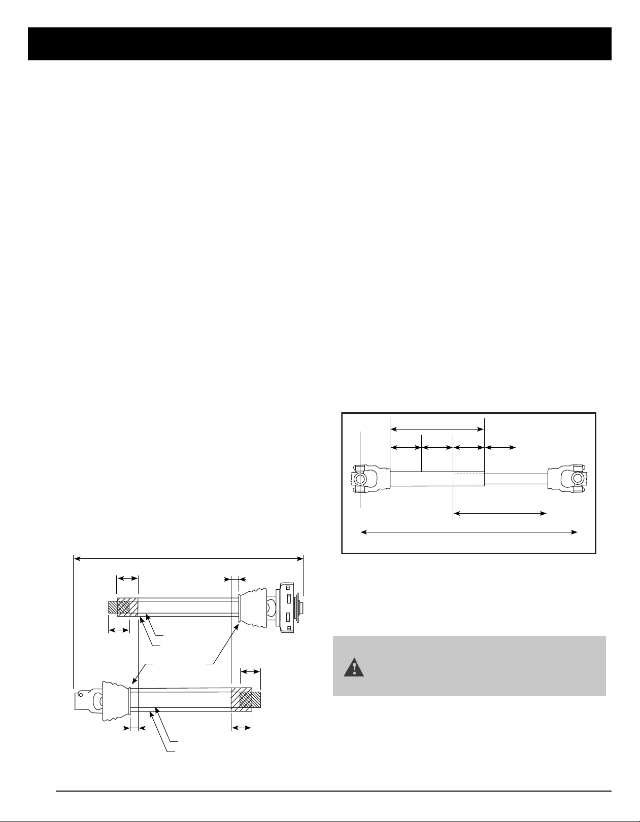
SIZING THE PTO SHAFT
Refer to Figure 1
1. Detach the driveline from tractor PTO shaft and
pull outer and inner drivelines apart.
2. Reattach outer driveline to tractor PTO shaft.
Pull on inner and outer drivelines to ensure
universal joints are properly secured.
3. Hold inner and outer drivelines parallel to each
other:
a. Measure 1” (“B” dimension) back from
outer driveline universal joint shield and
make a mark at this location on the inner
driveline shield.
b. Measure 1” (“B” dimension) back from
inner driveline universal joint shield and
make a mark at this location on the outer
driveline shield.
4. Remove driveline from tractor and gearbox
shafts.
5. Measure from end of inner shield to scribed
mark (“X” dimension). Cut o inner shield at the
mark. Cut same amount o the inner shaft (“X1”
dimension).
6. Measure from end of outer shield to scribed
mark (“Y” dimension). Cut o outer shield at
the mark. Cut same amount o the outer shaft
(“Y1” dimension).
7. Remove all burrs.
8. Continue with “Check Driveline Maximum
Length”.
INNER SHAFT
INNER DRIVELINE
OUTER DRIVELINE
INNER SHIELD
OUTER SHAFT
OUTER SHIELD
UNIVERSAL
JOINT SHIELD
TRACTOR END
IMPLEMENT END
Figure 1 - Driveline Shortening
A
B
B
X
Y
X1
Y1
FREE LENGTH IMPLEMENT END
INNER PROFILEOUTER PROFILE
1/3 1/3 1/3 1/3 1/3
OVERLAP
MAXIMUM ALLOWABLE LENGTH
Outer Shielding has been removed for clarity.
FREE LENGTHTRACTOR END
Figure 2 - Driveline Maximum Extended Length
CHECK DRIVELINE MAXIMUM
LENGTH
Refer to Figure 2
Make sure driveline’s collapsible length is
acceptable.
The driveline maximum allowable length must,
when fully extended, have a minimum overlap
of the profile tubes by not less than 1/3 the free
length with both inner and outer profile tubes
being of equal length.
1. Apply multi-purpose grease to the inside of the
outer shaft and reassemble the driveline.
2. Assemble the two driveline profiles together
with 1/3 of the profile tubes overlapping as
shown below. Once assembled, measure and
record the maximum allowable length for future
reference.
3. Attach inner driveline yoke to the cutter’s
gearbox shaft. Attach outer driveline yoke to
the tractor’s PTO shaft.
4. Move yoke ends of driveline back and forth to
insure they are secured to the tractor and cutter
shafts. Reattach any end that is loose.
5. Hook driveline safety chain on the tractor end
of driveline to cutter frame. Re-latch safety
chain to the driveline shield.
MODIFYING PTO
IMPORTANT: Small chains are supplied with
the driveline. They must be attached to the
inner and outer driveline shields and to the
tiller and tractor to restrict shield rotation.
This manual suits for next models
2
Table of contents
Popular Cutter manuals by other brands

TYROLIT Hydrostress
TYROLIT Hydrostress PPH25RR Series Operating instructions and spare parts list

METRO PROFESSIONAL
METRO PROFESSIONAL GVC1002 instruction manual

MSW Motor Technics
MSW Motor Technics MSW-PN-100 user manual

Makita
Makita SC130DRA instruction manual

Kubota
Kubota AP-SC4060 Operator's manual

Roberts
Roberts 10-63 owner's manual


