Cozy Cab 355-D User manual

'- ccz CR, ",
'..." '
'." ,
;,...,...'.,!e./i
, .,.' ,.' ',' , 5
MOUNTING INSTRUCTIONS
With Replacement Parts Listing For
TORO 355-D/455-D ROPS CAB
A-11147
I-
OPTIONS
4-13069 Heater Kit Option
4-13072 Flashing Light Kit
(l, 4-13070 Headlight Kit
4-13071 Defroster Fan Kit
4-11067 Door Screen Kit
~Manufactured by'
~TOAf PRODUCTS
OF LITCHFIELD, INC,
BOX 718 .LITCHFIELD,MINNESOTA55355
(320) 693-3221 Fax: (320) 693-7252
1-800-222-5463 05-10316
October 97

'NOTE:
Ifthe optional heater kit is to be installed, it is recommended that the hose
connects to the engine be made before mounting the cab.
MOUNTING INSTRUCTIONS
With Replacement Parts Listing For
TORO 355-D/455-D ROPS CAB
""PLEASE COMPLETELYREVIEW INSTRUCTIONS BEFORE MOUNTING.
Ifyou have any questions or comments please call 1-800-222-5438 and ask for
technical assistance with the Toro 355/455 RapS cab mounting.
PREPARATION OF MACHINE
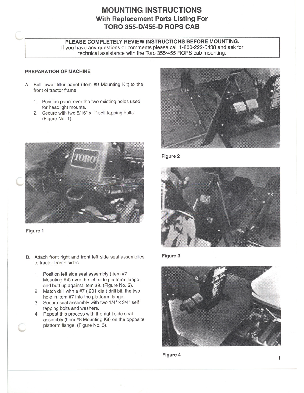
A. Bolt lower filler panel (Item #9 Mounting Kit)to the
front of tractor frame.
1. Position panel over the two existing holes used
for headlight mounts.
2. Secure with two 5/16" x 1" self tapping bolts.
(Figure No.1).
~-
Figure 1
B. Attach front right and front left side seal assemblies
to tractor frame sides.
c
1. Positionleft side seal assembly (Item#7
Mounting Kit) over the left side platformflange
and butt up against Item #9. (Figure No.2).
2. Match drill with a #7 (.201 dia.) drill bit, the two
hole in Item #7 into the platform flange.
3. Secureseal assemblywith two 1/4"x 3/4" self
tapping boltsand washers.
4. Repeatthis process with the right side seal
assembly (Item#8 Mounting Kit) on the opposite
platform flange. (Figure No.3).
Figure 2
Figure 3
Figure 4 1
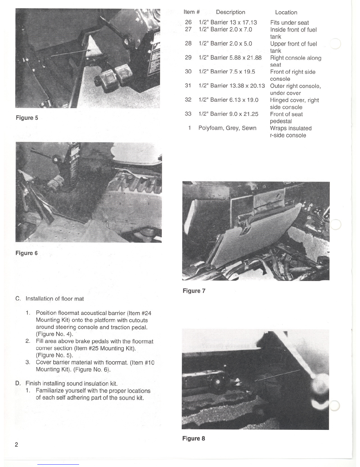
Figure 5
FigUre6
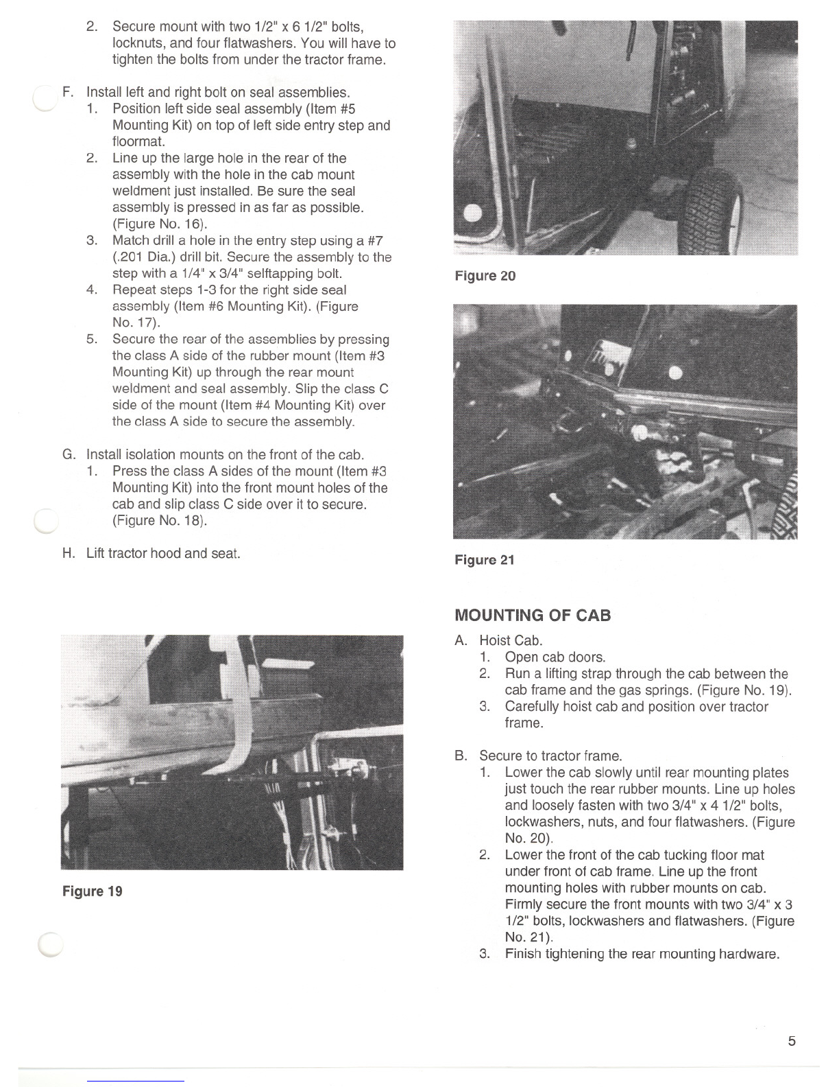
C. Installationof floor mat
1. Positionfloormat acoustical barrier (Item #24
Mounting Kit) onto the platformwith cutouts
around steering console and traction pedal.
(Figure No.4).
2. Fillarea above brake pedals with the floormat
corner section (Item #25 Mounting Kit).
(Figure No.5).
3. Cover barrier material with floormat. (Item #10
MountingKit). (Figure No.6).
D. Finish installingsound insulation kit.
1. Familiarizeyourself with the proper locations
of each self adhering part of the sound kit.
2
Item # Description
26 1/2" Barrier 13 x 17.13
27 1/2" Barrier 2.0 x 7.0
Location
Fits under seat
Inside front of fuel
tank
Upperfront of fuel
tank
Rightconsole along
seat
Front of right side
console
Outer right console,
undercover
Hinged cover, right
side console
Frontof seat
pedestal
Wraps insulated
r-side console
Figure 7
Figure 8
- )
-
28 1/2" Barrier 2.0 x 5.0
29 1/2" Barrier 5.88 x 21.88
30 1/2" Barrier 7.5 x 19.5
31 1/2" Barrier 13.38x 20.13
32 1/2" Barrier 6.13 x 19.0
33 1/2" Barrier 9.0 x 21.25
Polyfoam,Grey, Sewn
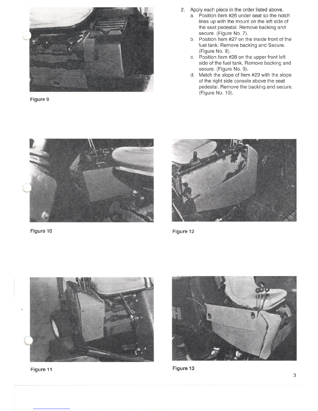
Figure 9
Figure 10
Figure 11
I
2. Apply each piece in the order listed above.
a. Position Item #26 under seat so the notch
lines up with the mount on the left side of
the seat pedestal. Remove backing and
secure. (Figure No.7).
b. Position Item #27 on the inside front of the
fuel tank. Remove backing and Secure.
(Figure No.8).
c. Position Item #28 on the upper front left
side of the fuel tank. Remove backing and
secure. (Figure No.9).
d. Match the slope of Item #29 with the slope
of the rightside console abovethe seat
pedestal. Removethe backing and secure.
(Figure No.1 0).
Figure 12
Figure 13 3

e. Position Item #30 on the front of the right
side console making sure the holes inthe
barrier material line up with the four bolts in
the panel. Removethe backing and secure.
(Figure No. 11).
f. Position Item #31 below the hinged cover
on the outside of the right side console.
Removethe backing and secure. (Figure
No. 12).
Figure 14
g. Position Item#32 over the hinged cover on
the outside of the right side console.
Removethe backing and secure. (Figure
No. 13).
h. Position Item #33 on the removable front of
the seat pedestal making sure the holes line
up with the knobs. Remove backing and
secure. (Figure No. 14).
E. Attach rear mountweldment to tractor frame.
1. Positionthe rear mount weldment (Item #2
Mounting Kit) across the tube located at the
rear of the operator area of the tractor. (Figure
No. 15).
Figure 15
4
Figure 16
)
Figure 17
:)
Figure 18
2. Secure mountwith two 1/2"x 61/2" bolts,
locknuts, and four flatwashers. You will haveto
tighten the bolts from under the tractor frame.
'- F. Install left and right bolt on seal assemblies.
1. Position left side seal assembly (Item #5
Mounting Kit) on top of left side entry step and
floormat.
2. Line up the large hole in the rearof the
assembly with the hole in the cab mount
weldment just installed. Be sure the seal
assembly is pressed in as far as possible.
(Figure No. 16).
3. Match drill a hole in the entry step usinga #7
(.201 Dia.) drill bit. Securethe assembly to the
step with a 1/4"x 3/4" selftapping bolt.
4. Repeatsteps 1-3 for the right side seal
assembly (Item #6 Mounting Kit). (Figure
No. 17).
5. Securethe rear of the assemblies by pressing
the class A side ofthe rubber mount (Item #3
Mounting Kit) upthrough the rear mount
weldment and seal assembly. Slip the class C
side of the mount (Item #4 Mounting Kit) over
the class A sideto secure the assembly.
G. Install isolation mounts on the front of the cab.
1. Pressthe class A sides of the mount (Item #3
Mounting Kit) into the front mount holes of the
cab and slip class C side over it to secure.
(Figure No. 18).
-- H. Lifttractor hood and seat.
Figure 19
'-
Figure20
Figure21
MOUNTING OF CAB
A. Hoist Cab.
1. Open cab doors.
2. Run a lifting strap through the cab between the
cab frame and the gas springs. (Figure No. 19).
3. Carefully hoist cab and position over tractor
frame.
B. Secure to tractor frame.
1. Lowerthe cab slowly until rear mounting plates
just touch the rear rubber mounts. Line up holes
and looselyfasten with two 3/4" x 41/2" bolts,
lockwashers, nuts, and four flatwashers. (Figure
No. 20).
2. Lowerthe front of the cab tucking floor mat
under front of cab frame. Line up the front
mounting holes with rubber mounts on cab.
Firmly securethe front mounts with two 3/4" x 3
1/2" bolts, lockwashers and flatwashers. (Figure
No. 21).
3. Finishtightening the rear mounting hardware.
5
C. Install larger entry step pad to left side of tractor
frame.
1. Position entry step pad (Item #22 Mounting Kit)
with the two bare edges facing the tractor
frame. (Figure No. 22).
2. Secure with three 1/4"x 1 1/4" bolts,
flatwashers and nuts.
WIRING OF CAB
A. Runthe power lead along the right hand side of cab
to the outside of the right side console and in
through the back side of the hinged cover. (Figure
No. 23).
B. Connect the terminal to the connection on the rear
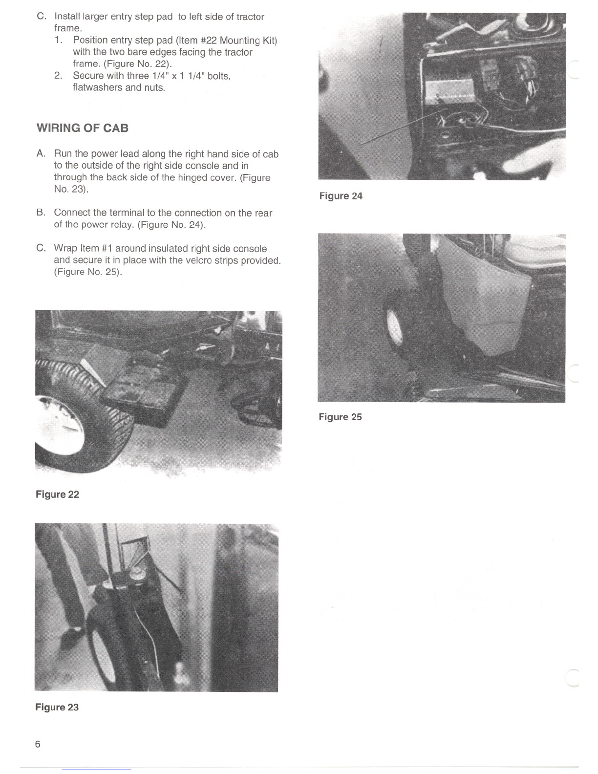
of the power relay. (Figure No. 24).
C. Wrap Item #1 around insulated right side console
and secure it in place with the velcro strips provided.
(Figure No. 25).
Figure 22
Figure 23
6
Figure 24
Figure 25

REPLACEMENT PARTS
MOUNTING KIT TORO 355-D/455-D CAB
4-14115
ITEM QTY PART NO. DESCRIPTION
11 4-13077 Rightside console cover assembly
11-35623 Insulation, outer console cover
1 1-35624 Insulation,front console cover
1 1-35625 Insulation, inside console cover
.4' 3-13854 Velcro, 1"wide hook
.4' 3-10635 Velcro, 1"wide loop
2 1 2-14405 Rear mount weldment
3 4 3-11273 Rubber mountclass A
4 4 3-11275 Rubber mount class C
51 4-13046 Left side seal assembly
1 1-35423 Bolt on seal panel Lt
3' 3-11280 90 deg clip on bubble rubber Lg.
3' 3-15068 180 deg clip on bubble rubber 3/8"
614-13047 Rightside seal assembly
1 1-35426 Bolt on seal panel Rt
3' 3-11280 90 deg clip on bubble rubber Lg.
3' 3-15068 180 deg clip on bubble rubber 3/8"
23-10319 Plastic hole plug 1 3/8" Dia.
7 1 4-13044 Rightfront seal assembly
1 1-35425 Rightfront seal panel
2' 3-11280 90 deg clip on bubble rubber Lg.
81 4-13043 Leftfront seal assembly
1 1-35422 Left front seal panel
2' 3-11280 90 deg clip on bubble rubber Lg.
91 4-13045 Front bolt on seal assembly
1 1-35427 Front bolt on panel
2' 3-15068 180deg clip on bubble rubber 3/8"
10 1 1-35619 Floormat
11 2 3-10425 3/4"-10NC x 31/2" Gr. 5 Bolt
12 6 3-10142 3/4" Flatwasher
13 43-10081 3/4" Lockwasher
14 2 3-10069 3/4"-10NC Hex nut
15 2 3-10426 3/4"-10NC x 4" Gr. 5 Bolt
16 8 3-10127 1/4" x 3/4" Selftap
17 2 3-10084 1/4" Flatwasher
18 2 3-15121 1/2"-13NCx 61/2" Gr. 5 Bolt
19 4 3-10087 1/2" Flatwasher
20 23-10379 1/2"-13NC Nylock hex nut
21 3 3-10009 5/16"-18NC x 1 1/8" Gr. 5 Bolt
22 1 4-13076 Foot step assembly
1 1-35615 Footstep extension
23 3 3-10072 5/16"-18NC Nylock hex nut
24 1 3-16069 Barrier, floormat
25 13-16068 Barrier, corner section
26 13-16065 Barrier, seat mount
27 1 3-16066 Barrier, left seat side
\. 28 1 3-16067 Barrier, upper left fuel tank
29 1 3-16070 Barrier, inside right side console
30 1 3-16063 Barrier, front console cover
31 1 3-16062 Barrier, outer lower console
32 1 3-16061 Barrier, hinged console cover, outside 7

33
34
35
1
2
6
3-16064
3-10380
3-10085
Barrier,front seat pedestal
5/16" x 1 Selftap
5/16" Flatwasher
)
[AB ASSEIflLY
)
)
8
l
9
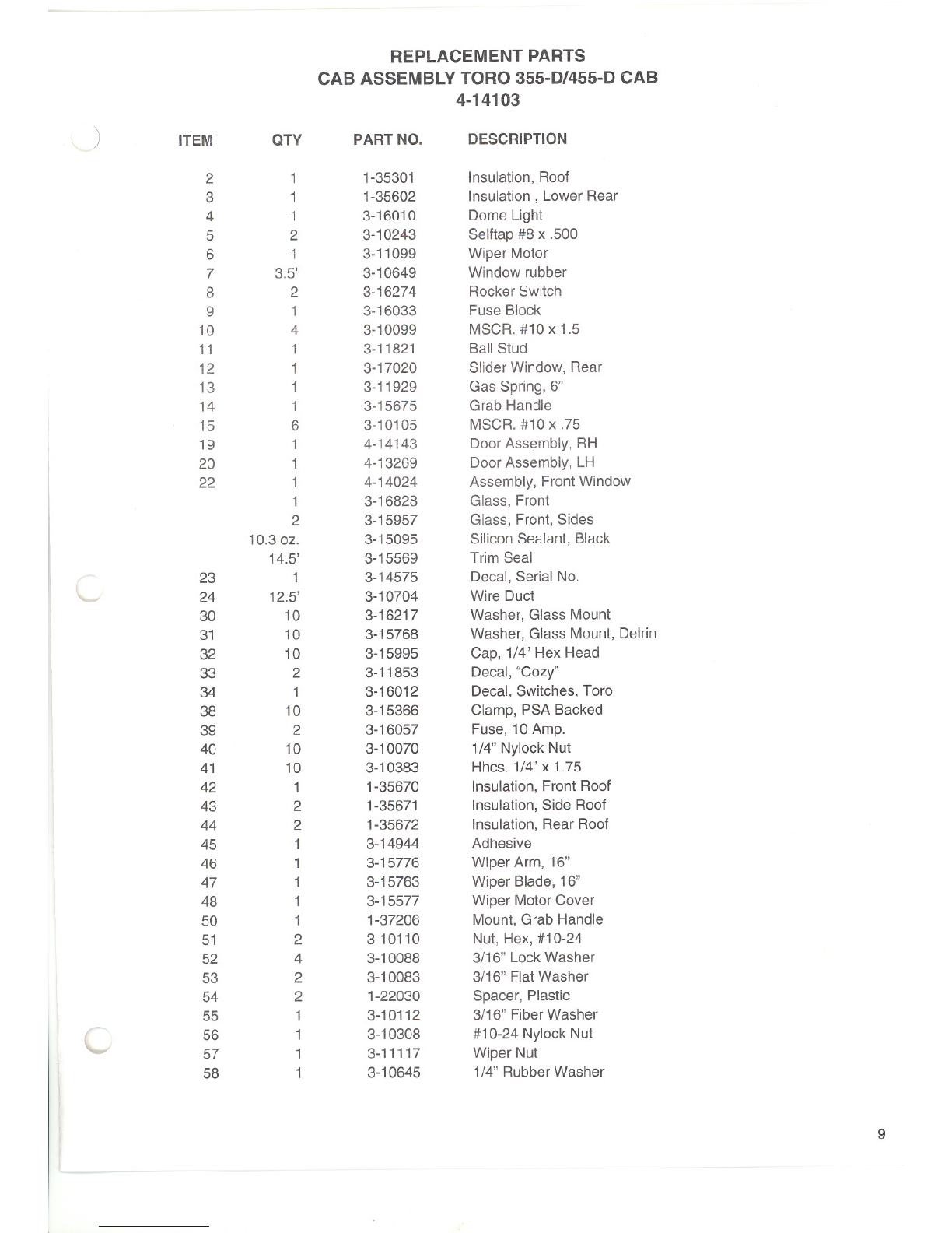
REPLACEMENT PARTS
CAB ASSEMBLYTORO 355-D/455-D CAB
4-14103
)ITEM QTY PART NO. DESCRIPTION
2 1 1-35301 Insulation, Roof
3 1 1-35602 Insulation, Lower Rear
4 1 3-16010 Dome Light
5 2 3-10243 Selftap #8 x .500
6 1 3-11099 Wiper Motor
7 3.5' 3-10649 Window rubber
8 2 3-16274 Rocker Switch
9 1 3-16033 Fuse Block
10 4 3-10099 MSCR. #10 x 1.5
11 1 3-11821 Ball Stud
12 1 3-17020 Slider Window, Rear
13 1 3-11929 Gas Spring, 6"
14 1 3-15675 Grab Handle
15 6 3-10105 MSCR. #10 x .75
19 14-14143 Door Assembly, RH
20 14-13269 Door Assembly, LH
22 14-14024 Assembly, FrontWindow
1 3-16828 Glass, Front
2 3-15957 Glass, Front, Sides
10.3 oz. 3-15095 Silicon Sealant, Black
14.5' 3-15569 Trim Seal
23 1 3-14575 Decal, Serial No.
L24 12.5' 3-10704 Wire Duct
30 10 3-16217 Washer, Glass Mount
31 10 3-15768 Washer, Glass Mount, Delrin
32 10 3-15995 Cap, 1/4" Hex Head
33 2 3-11853 Decal, "Cozy"
34 1 3-16012 Decal, Switches, Toro
38 10 3-15366 Clamp, PSA Backed
39 2 3-16057 Fuse, 10Amp.
40 10 3-10070 1/4" Nylock Nut
41 10 3-10383 Hhcs. 1/4"x 1.75
42 1 1-35670 Insulation, Front Roof
43 2 1-35671 Insulation, Side Roof
44 2 1-35672 Insulation, Rear Roof
45 1 3-14944 Adhesive
46 1 3-15776 Wiper Arm, 16"
47 1 3-15763 Wiper Blade, 16"
48 1 3-15577 Wiper Motor Cover
50 1 1-37206 Mount, Grab Handle
51 2 3-10110 Nut, Hex,#10-24
52 43-10088 3/16" Lock Washer
53 2 3-10083 3/16" Flat Washer
54 21-22030 Spacer, Plastic
55 13-10112 3/16" Fiber Washer
C56 13-10308 #10-24 Nylock Nut
57 1 3-11117 Wiper Nut
58 1 3-10645 1/4" Rubber Washer

5/8" FiberWasher
5/8" x 1"Bushing
Hhcs. 5/16" x 1.75
5/16" FlatWasher
5/16" Nut
Gasket, Wiper Arm
Latch, RightSide Door
Roll Pin
11/16" Rubber Washer
3-12945
3-10716
3-12591
3-10085
3-10064
3-16305
3-15993
3-15576
3-16206
59
60
61
62
63
64
65
66
67
1
1
1
2
2
1
1
1
1
£@ ""~DI'"
SEE"""
VIEH-[
DETAIlF
'LJH lIIE ERn
SEwmA-A
0IDIDR,n
~ID-
fiJELiGiTSf1TGi
~""_""'~ID""'"""
."IfR'"
2' .-
'IIf"'ITGi
Rim! INSllE SIKMI [HAlL 0
~TARH
"",,1m <co," . "" "" '"'" F
W","""T~I~~'"
!fflSIglffA!i!!!L
10

REPLACEMENT PARTS
DOOR ASSEMBLY TORO 335-D/455-D CAB
4-13269 LEFT
ITEM
1
2
3
4
5
6
7
8
9
10
11
12
13
14
15
16
17
18
19
20
21
OTY
1
1
1
13.5 ft.
17ft.
2
1
1
1
1
1
1
3
8
2
2
4
8
3
1
1
PART NO.
2-14722
3-16517
3-16518
3-15952
3-10649
2-14731
3-15574
3-11821
3-10085
3-10077
3-10064
3-15969
3-12692
3-10070
3-10220
3-10219
3-10204
3-15995
3-10076
1-37207
3-16395
DESCRIPTION
Weldement, door (Leftdoor)
Glass, upper
Glass, lower
Trim Seal, 3/4"
Rubber,window, offset
Weldement, hinge (L.H. door)
Handle, exterior, black
Ball Stud, gas spring
Washer, flat, 5/16"
Washer, lock, 5/16"
Hex Nut, 5/16"
Rotary latch, left door
Bolt, M6 X 15X1.0
Hex Nut, Nylock, 1/4"-20
Bolt, 1/4" -20 X 1.00
Bolt, 1/4"-20 X 3/4"
Bolt, 1/4"-20 X 1.50
Cap, 1/4" Hex Head
Washer, Lock, 1/4"
Spacer, door handle
Decal, caution
SfUI{f{ B-B
lB
SE[TJ~[-[
\..
11

REPLACEMENT PARTS
DOOR ASSEMBLY, RH 4-14143
TORO 355-D/455-D
ITEM
1
2
3
4
5
6
7
8
9
QTY
1
1
1
13.5'
17'
2
4
4
4
PART NO.
2-14723
3-16517
3-16518
3-15952
3-10649
2-14732
3-10070
3-10204
3-15995
DESCRIPTION
Weldement, Door, Right
Glass, Upper Door
Glass, Lower Door
Trim Seal
Window Rubber
Weldment, Hinge
1/4" Nylock Nut
1/4" HHCS x 1.50
Cap, 1/4"Cap Screw
f\ 162"
I'
I'
"
I'
d:
"
II
"
'I
II
I,
Af 11:llllA
I
SECTION A-A
12
This manual suits for next models
2
Table of contents
Other Cozy Cab Lawn Mower Accessories manuals


