manuals.online logo
Brands
  1. Home
  2. •
  3. Brands
  4. •
  5. COZY
  6. •
  7. Furnace
  8. •
  9. COZY W252F and User manual

COZY W252F and User manual

This manual suits for next models

11

Other COZY Furnace manuals

COZY 90N30A and User manual

COZY

COZY 90N30A and User manual

COZY 90N A Series User manual

COZY

COZY 90N A Series User manual

COZY 90N30A and User manual

COZY

COZY 90N30A and User manual

COZY CF353C-H User manual

COZY

COZY CF353C-H User manual

COZY DVCF404B-R and User manual

COZY

COZY DVCF404B-R and User manual

COZY W251F and User manual

COZY

COZY W251F and User manual

COZY CF354C-R and User manual

COZY

COZY CF354C-R and User manual

COZY CDV255B and User manual

COZY

COZY CDV255B and User manual

COZY 90N30A and User manual

COZY

COZY 90N30A and User manual

COZY 90N30A and User manual

COZY

COZY 90N30A and User manual

COZY CDV155D User manual

COZY

COZY CDV155D User manual

COZY W255F and User manual

COZY

COZY W255F and User manual

COZY CF354C-R and User manual

COZY

COZY CF354C-R and User manual

COZY CDV142E User manual

COZY

COZY CDV142E User manual

COZY CF403D-H User manual

COZY

COZY CF403D-H User manual

COZY HEDV253A and User manual

COZY

COZY HEDV253A and User manual

COZY W506 User manual

COZY

COZY W506 User manual

COZY CDV155C User manual

COZY

COZY CDV155C User manual

COZY W251E User manual

COZY

COZY W251E User manual

COZY HEDV403 and User manual

COZY

COZY HEDV403 and User manual

COZY W255GPPR User manual

COZY

COZY W255GPPR User manual

COZY W255G User manual

COZY

COZY W255G User manual

COZY CF353C-H User manual

COZY

COZY CF353C-H User manual

Popular Furnace manuals by other brands

Unitary products group AHV8 UH installation manual

Unitary products group

Unitary products group AHV8 UH installation manual

VERDER CARBOLITE GERO RHF 14/8 Installation, operation and maintenance instructions

VERDER

VERDER CARBOLITE GERO RHF 14/8 Installation, operation and maintenance instructions

Tempstar B Series Service and technical support manual

Tempstar

Tempstar B Series Service and technical support manual

Carrier Performance 59SP5A Installation, start-up, operating and service and maintenance instructions

Carrier

Carrier Performance 59SP5A Installation, start-up, operating and service and maintenance instructions

Armstrong EG7H SERIES Installation and maintenance instructions

Armstrong

Armstrong EG7H SERIES Installation and maintenance instructions

Payne PG92ESA Installation, start-up, operating and service and maintenance instructions

Payne

Payne PG92ESA Installation, start-up, operating and service and maintenance instructions

NANOE Zetasinter Operation manual

NANOE

NANOE Zetasinter Operation manual

SUPREME FEM10-M2301CM-A Installation instructions and homeowner's manual

SUPREME

SUPREME FEM10-M2301CM-A Installation instructions and homeowner's manual

Johnson Controls TM9T User's information manual

Johnson Controls

Johnson Controls TM9T User's information manual

Fluke 9118A user manual

Fluke

Fluke 9118A user manual

Lennox EL195UHE Elite Series Unit information

Lennox

Lennox EL195UHE Elite Series Unit information

Intertherm M7RL Series user manual

Intertherm

Intertherm M7RL Series user manual

HDG Pelletmaster 15 Operation manual

HDG

HDG Pelletmaster 15 Operation manual

Nortek MG2S Series installation instructions

Nortek

Nortek MG2S Series installation instructions

VERDER CARBOLITE GERO ABF 8/28 Installation, operation and maintenance instructions

VERDER

VERDER CARBOLITE GERO ABF 8/28 Installation, operation and maintenance instructions

Goodman GMV9 Installation & operating instructions

Goodman

Goodman GMV9 Installation & operating instructions

SUPREME SUP10-M2301C Installation instructions and homeowner's manual

SUPREME

SUPREME SUP10-M2301C Installation instructions and homeowner's manual

Dettson AMT400B34-SM1PMA Installation instructions and homeowner's manual

Dettson

Dettson AMT400B34-SM1PMA Installation instructions and homeowner's manual

manuals.online logo
manuals.online logoBrands
  • About & Mission
  • Contact us
  • Privacy Policy
  • Terms and Conditions

Copyright 2025 Manuals.Online. All Rights Reserved.

GAS-FIREDVENTEDWALLFURNACE J
INSTALLATION AND
OPERATING INSTRUCTIONS
P/N 84502 REV. 11/04
IIL :
GAS W255F, W355F, W505F S W256F, W356F, W502F i
W506F
WARNING: If the information in this manual is not
followed exactly, a fire or explosion may result causing
property damage, personal injury or loss of life.
Do not store or use gasoline or other flammable vapors and
liquids in the vicinity of this or any other appliance.
WHAT TO DO IF YOU SMELL GAS:
•Do not try to light any appliance.
• Do not touch any electrical switch; do not use any phone in
your building.
• Immediately call your gas supplier from a neighbor's phone.
Follow the gas supplier's instructions.
• If you cannot reach your gas supplier, call the fire department.
INSTALLATION AND SERVICE MUST BE
PERFORMED BY A QUALIFIED INSTALLER,
SERVICE AGENCY OR THE GAS SUPPLIER.
umiRini_iin_
s_yARNING: Operation of this furnace when not connected to a properly installed and maintained venting I
em can result in Carbon Monoxide (C.O.) poisoning and possible death. For your safety, this furnace and I
Ithe venting system should be inspected at least annually by a qualified service person.
This appliance is equipped with ablocked flue switch designed to protect a_ainst a blocked flue condition.
The coating selected to provide longer life to the heat exchanger may smoke slightly upon initial firing. Please
3rovide adequate ventilation if this occurs.
This heater may be installed without recessing into stud space by using optional FSK (Free Standing Kit).
This unit isnot approved for installation in mobile homes, greenhouses, or environlnents involving dusty, wet,
corrosive, or explosive conditions. Such conditions will invalidate the warranty and may create unsafe conditions.
THIS UNIT IS NOT TO BE INSTALLED IN MOBILE HOMES.
CONTENTS
hmoduction ................................................ 2
Specifications .............................................. 2
Safety Rules................................................. 3
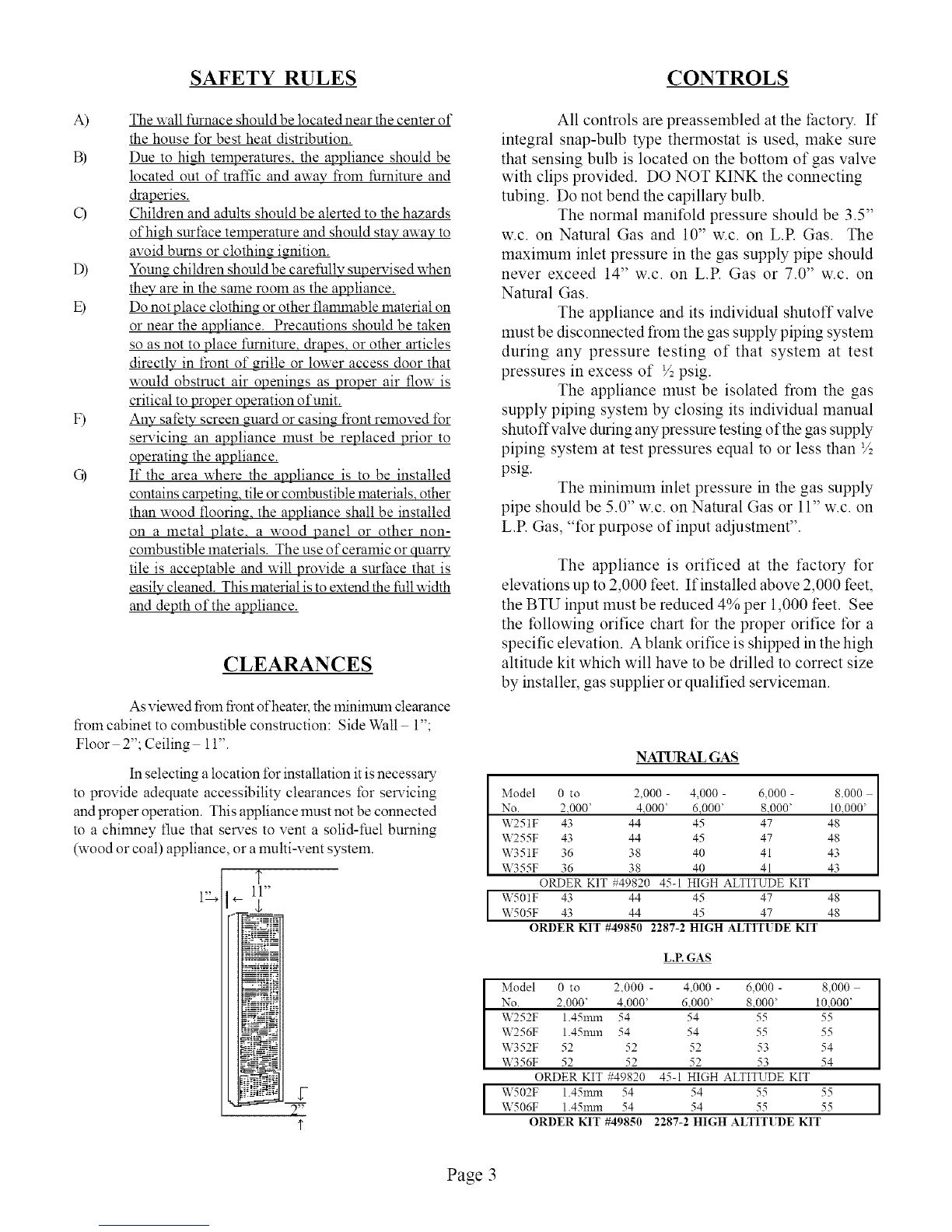
Clemances .................................................... 3
Controls ........................................................ 3
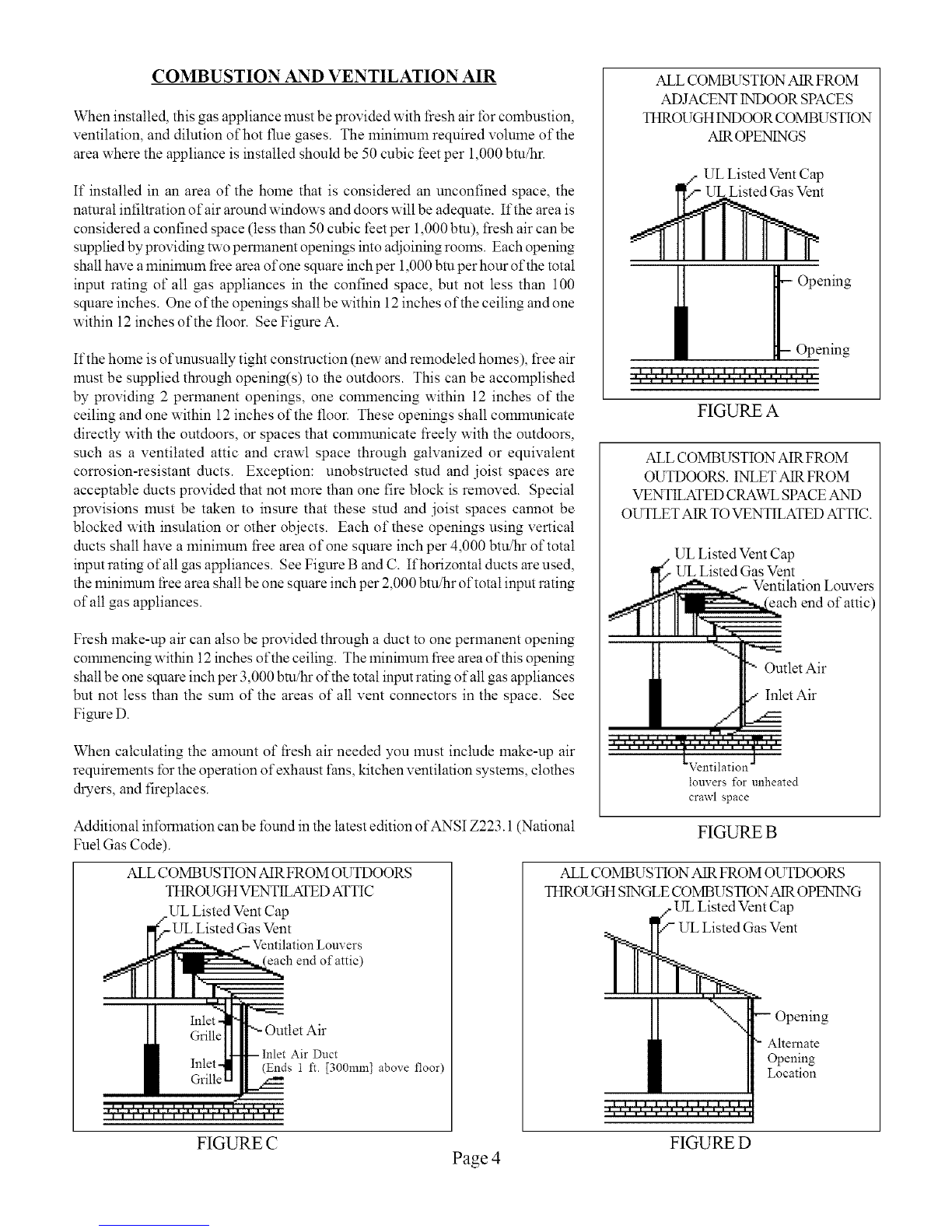
Combustion & Ventilation Air................... 4
Venting .......................................................... 5,6
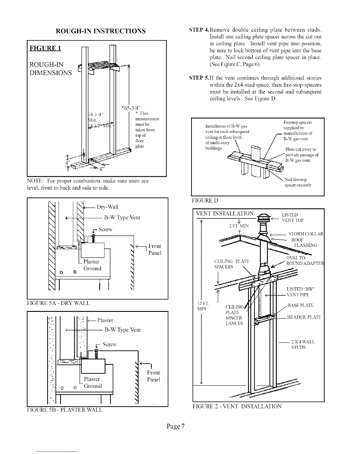
Rough-In Instructions ................................ 6
Installation .................................................... 8
Wiring Instructions ..................................... 9
Rear Register Kit Instructions .................................... 9
Lighting Instructions ................................................... 10!11
Pilot Adjustment ........................................................... 12
Burner Flame Adjustment ............................................ 12
Maintenance Instructions ........................................... 12
WFF81 Fro1Instructions .............................................. 13/14
Trouble Shoothlg Chart................................................ 15/16
Parts Drawing ................................................................ 17
Parts List........................................................................ 18
Warranty. ....................................................................... 20
READ CAREFULLY BEFORE INSTALLING UNIT
These installation instructions are a general guide, and do not supersede applicable local codes and ordinances. Before planning or
making the installation, be sure it complies with all phases of the local heating codes. Or, in the absence of local codes, with the latest
edition of the National Fuel Gas Code, ANSI.Z223.1. In Canada, see the current installation code CAN1-B 149.
The appliance, when installed, must be electrically _ounded in accordance with local codes or, in the absence of local codes, with
the latest edition of the National Electrical Code ANSI/NFPA No. 70. In Canada, see the current Canadian Electrical Code
C5AC22.1.
The ANSI standards are available from the American Gas Association, 1515 Wilson Blvd., Arlington, Virginia 22209.
The NFPA standards are available from the National Fire Protection Association, Batterymarch Park, Quincy, MA. 02269.
Canadian standards are available fiom International Approval SelaTices,178 Rexdale Blvd.,Etobicoke,Ontario, Canada M9W IR3.
NOTE: If optional rear register kit is to be used, see supplemental installation instructions (No. 84504) and section marked
"Special Instructions for Rear Register Kit Application" prior to installation of Rough-In.
INTRODUCTION
THIS IS A GAS-FIRED, GRAVITY VENTED WALL FURNACE THAT WILL OPERATE SAFELY AND PROVIDE AN
EFFICIENT SOURCE OF HEAT WHEN INSTALLED, OPERATED AND MAINTAINED AS RECOMMENDED IN THESE
INSTALLATION AND OPERATING INSTRUCTIONS. READ THESE INSTRUCTIONS THOROUGHLY BEFORE
INSTALLING, SERVICING, OR USING THE APPLIANCE. IF YOU DO NOT UNDERSTAND ANY PART OF THESE
INSTRUCTIONS, CONSULT LOCAL AUTHORITIES, OTHER QUALIFIED INSTALLERS, SERVICE AGENCIES, THE GAS
SUPPLIER OR THE MANUFACTURER. SPECIFICATIONS
Your vented wall furnace comes packed in a single carton. (For wall thermostat models that includes the thermostat, thermostat
wire, and insulated staples). Before installing the wall furnace check the rating plate to verify that the Model Nmnber is correct
and that the wall furnace is equipped for the type gas you intend to use.
Model Type _pe BTUiHr. \_m Gas Shpg.
No. Collffol Gas Input Size Inlet FINISHED DIMENSIONS \Vt.
SINGLE _I__LL FURNACE
1/2' 16-1/2' Wx68"Hx6-1i2"D 90 Lbs.
1/2" 16-1i2"Wx68"Hx6-1i2"D 90 Lbs.
W251F Snap Bulb Nat. 25.000 4"
W255F \Vall Star Nat. 25.000 4"
W252F Snap Bulb L.P. 25,000 4"
W256F \Vall Star L.P. 25,000 4"
W351F Snap Bulb Nat. 35.000 4"
W355F \Vall Star Nat. 35.000 4"
W352F Snap Bulb L.P. 35,000 4"
W356F \Vall Star L.P. 35.000 4"
W501F Snap Bulb Nat. 50,000 4"
W505F Wall Star Nat. 50,000 4"
W502F Snap Bulb L.P. 50,000 4"
W506F Wall Stat L.P. 50,000 4"
One or two fan kits may be used on dual-wall furnace.
1/2" 16-1 i2"Wx68"Hx6-1/2"D 90 Lbs.
1/2" 16-1i2"Wx68"Hx6-1/2"D 90 Lbs.
1/2" 16-1i2"Wx68"Hx6-1i2"D 90 Lbs.
DUAL V_LL FUI_NACE
1/2" 16-1i2"Wx68"Hx6-1i2"D 134 Lbs
REAR REG. KIT
Model \Veidlt
40542 5 Lbs.
40542 5 Lbs.
40542 5 Lbs.
40542 5 Lbs.
40542 5 Lbs.
40542 5 Lbs.
40542 5Lbs.
40542 5Lbs.
Page 2
NiA NiA
NiA NiA
NiA NiA
NiA NiA
FANKIT
Model \Vt.
\tTF81 10 Ibs
\\,TF81 10 Ibs
V_TF81 101bs
\tTF81 10 Ibs
WFF81 10 Ibs
WFFS1 10 Ibs
WFF81 10 Ibs
V_TF81 101bs
\,_TF81 101bs
\,_TF81 101bs
\,_TF81 101bs
\,_TF81 101bs
SAFETY RULES CONTROLS
A)
c)
D)
E)
F)
Q
The wall furnace should be located near the center of
the house tSr best heat distribution.
Due to high temperatures, the appliance should be
located out of traffic and away from furniture and
_eries.
Children and adults should be alerted to the hazards
of high surface temperature and should stay away to
avoid burns or clothing ignition.
Youn_ children should be carefully supelwised when
they are in the same morn as the appliance.
Do not place clothin_ or other flammable material on
or near the appliance. Precautions should be taken
so as not to place furniture, drapes, or other articles
directly in front of m-itle or lower access door that
would obstruct air openings as proper air flow is
critical to proper operation of unit.
Any safety screen guard or casing fiont removed for
sel_qcin_ an appliance must be replaced prior to
operating the appliance.
If the area where the appliance is to be installed
contains carpeting, tile orcombustible materials, other
than wood flooring, the appliance shall be installed
on a metal plate, a wood panel or other non-
combustible materials. The use of ceramic or quarry
tile is acceptable and will provide a surface that is
easily cleaned. This material is to extend the full width
and depth of the appliance.
CLEARANCES
As viewed t?om front ofheater, the lninimum clemance
tiom cabinet to combustible construction: Side Wall 1";
Floor 2"; Ceiling 11".
In selecting a location for installation it is necessary
to provide adequate accessibility clearances for selaqcing
and proper operation. This appliance must not be connected
to a chimney flue that serves to vent a solid-fuel burning
(wood or coal) appliance, or a multi-vent system.
T
1_ 11"
l,
2-
All controls are preassembled at the factory. If
integral snap-bulb type thermostat is used, make sure
that sensing bulb is located on the bottom of gas valve
with clips provided. DO NOT KINK the connecting
tubing. Do not bend the capillary bulb.
The normal manifold pressure should be 3.5"
w.c. on Natural Gas and 10" w.c. on L.R Gas. The
maximum inlet pressure in the gas supply pipe should
never exceed 14" w.c. on L.R Gas or 7.0" w.c. on
Natural Gas.
The appliance and its individual shutoff valve
must be disconnected from the gas supply piping system
during any pressure testing of that system at test
pressures in excess of ½ psig.
The appliance must be isolated from the gas
supply piping system by closing its individual manual
shutoffvalve during any pressure testing of the gas supply
piping system at test pressures equal to or less than ½
psig. The minimum inlet pressure in the gas supply
pipe should be 5.0" w.c. on Natural Gas or 11" w.c. on
L.R Gas, "for purpose of input adjustment".
The appliance is orificed at the factory for
elevations up to 2,000 feet. If installed above 2,000 feet,
the BTU input must be reduced 4% per 1,000 feet. See
the following orifice chart for the proper orifice for a
specific elevation. A blank orifice is shipped in the high
altitude kit which will have to be drilled to correct size
by installer, gas supplier or qualified serviceman.
NATURAL GAS
I
Model 0 to 2,000 - 4,000 - 6,000 - 8,000 ]
m
No. 2.000' 4.000' 6.000' 8.000' 10.000' I
1
W251F 43 44 45 47 48
W255F 43 44 45 47 4348
W351F 36 38 40 41 43
W355F 36 38 40 41
ORDER KIT #49820 45-1 HIGH ALTITUDE KIT
IW501F 43 44 45 47 48 IW505F 43 44 45 47 48
ORDERKIT #49850 2287-2HIGHALTITUDEKIT
L.P. GAS
Model 0 to 2_000 - 4.000 - 6,000 - 8,000
No. 2_000' 4_000' 6_000' 8_000' 10_000'
W252F 1.45nma 54 54 55 55
W256F 1.45nun 54 54 55 55
W352F 52 52 52 53 54
W356F 52 52 52 53 54
ORDER KIT #49820 45-1 HIGH ALTITUDE KIT
IW502F 1.45mm 54 54 55 55 I
W506F 1.45nml 54 54 55 55
ORDER KIT #49850 2287-2HIGHALTITUDEKIT
Page 3
COMBUSTION AND VENTILATION AIR
When installed, this gas appliance must be provided with flesh air for combustion,
ventilation, and dilution of hot flue gases. The minimum required volume of the
area where the appliance is installed should be 50 cubic feet per 1,000 bin/hr.
If installed in an area of the home that is considered an unconfined space, the
natural infiltration of air around windows and doors will be adequate. If the area is
considered a confined space (less than 50 cubic feet per 1,000 btu), fresh air can be
supplied by providing two permanent openings into adjoining rooms. Each opening
shall have a minimum flee area of one square inch per 1,000 bm per hour of the total
input rating of all gas appliances in the confined space, but not less than 100
square inches. One of the openings shall be within 12 inches of the ceiling and one
within 12 inches of the floor. See Fimlre A.
If the home is of unusually tight construction (new and remodeled homes), tree air
must be supplied through opening(s) to the outdoors. This can be accomplished
by providing 2 permanent openings, one commencing within 12 inches of the
ceiling and one within 12 inches of the floor. These openings shall communicate
directly with the outdoors, or spaces that comlnunicate freely with the outdoors,
such as a ventilated attic and crawl space through galvanized or equivalent
corrosion-resistant ducts. Exception: unobstructed stud and joist spaces are
acceptable ducts provided that not more than one fire block is removed. Special
provisions must be taken to insure that these stud and joist spaces cannot be
blocked with insulation or other objects. Each of these openings using vertical
ducts shall have a minimum flee area of one square inch per 4,000 btu/hr of total
input rating of all gas appliances. See Fimlre B and C. If horizontal ducts are used,
the minimum flee area shall be one square inch per 2,000 btu/hr of total input rating
of all gas appliances.
Fresh make-up air can also be provided through a duct to one permanent opening
colrnnencingwithin 12inches oftheceiling. Theminimum free areaofthis opening
shall be one square inch per 3,000 bm/hr ofthe total input rating ofatl gas appliances
but not less than the sum of the areas of all vent connectors in the space. See
Fibre D.
When calculating the amount of fresh air needed you must include make-up air
requirements tbr the operation of exhaust fans, kitchen ventilation systems, clothes
dryers, and fireplaces.
ALL COMBUSTION AIR FROM
ADJACENT INDOOR SPACES
THROI_YGHINDOOR COMBrcYSTION
AIR OPENINGS
UL Listed Vent Cap
Vent
i I Opening
Opening
.,..,..,..,..,..,.,..,..,..,..,..,..,..,..,..,..,..
FIGURE A
ALL COMBUSTION AIR FROM
OUTDOORS. INLET AIR FROM
VENTILATED CRAWL SPACE AND
OUTLET AIR TO VENTILATED ATTIC.
UL Listed Vent Cap
UL Listed Gas Vent
ntilation Louvers
ch end of attic)
"" Outlet Air
/Inlet Air
............--.....%: ..--..
....... [\;eiltil_t'io_ j' '
louvers for unheated
crawl space
Additional information can be found in the latest edition of ANSI Z223.1 (National
Fuel Gas Code). FIGURE B
ALL COMBUSTION AIR FROM OUTDOORS
THROI_IGHVENTILATED ATTIC
.UL Listed Vent Cap
-UL Listed Gas Vent
each end of attic)
Air Duct
(Ends 1 ft. [300mm] above floor)
ALL COMBUSTION AIR FROM OUTDOORS
THROUGH S1NGLECOMBUSTION AIR OPEN1NG
UL Listed Vent Cap
Gas Vent
I I i
I[ "_',. -- Opening
Alternate
• Opening
I Location
.,..,..,..,..,..,..,.,..,..,..,..,..,.:
FIGURE C Page 4 FIGURE D
USING ADJACENT STUD SPACE
FOR ALL COMBUSTION AIR
FROM OUTSIDE
HOLES CONNECTING
TO VENTILATED ATTIC
CEILING
PLATE
AIR
GRILLE
FLOOR
PLATE
HOLES CONNECTING TO
VENTILATED CRAWL
SPACE
BASED ON 4,000 BTU OF TOTAL INPUT
RATING OF ALL GAS APPLIANCES, THE
HEATER ONLY REQUIRES A MINIMUM
FREE AREA OF:
SQUARE HOLE SQUARE
BTU IN. SIZE IN.
25,000 6.25 1" .785
35,000 8.75 1.5" 1.76
50,000 12.50 2" 3.14
VENTING
This appliance must be properly connected to a venting
system. Consult local ordinances governing venting. Install only
UL listed type BW 4" oval gas vent. When the vent enters the
attic, a listed type B- 1 round flue pipe may be used. See Figure
2, Page 7.
Vent pipe must connect to the wall furnace header plate
with a"B" vent base plate and terminate with a cap at a point at
least 12 foot above the bottom of the wall furnace, two feet
above any obstacle within a 10 foot radius, and at least 3 foot
above the roof.
Provisions must be made for adequate combustion and
ventilation air.
This appliance is equipped with a manual reset blocked
flue switch designed to protect against a blocked flue condition,
which would cause combustion products to spill back into the
living quarters. NOTE: A partially blocked, inadequate, or
disconnected vent system may not activate the switch.
Discoloration of the grille is an indication of a bad vent. If this
occurs, the vent can be checked by a qualified serviceman using
a draft gauge. After 15 minutes the gauge should read between
-.02 up to -.04 inches w.c. Vent must be checked at the
beginning of each heating season.
The switch when activated on a bulb control burner will
extinguish the pilot flame, on a thermostat controlled burner, the
thermostat circuit will be broken, turning offthe main burner
flame. Before the heater can be relit, the reset button must be
activated. See Figure B for location of the manual reset blocked
flue switch. To reset the switch, insert a slender rigid object
(i.e. screwdriver) through the front panel louvers and push the
reset button down. See Figure B-1. However, you may have
to remove the front panel, then reset the switch and reinstall the
front panel to relight heater. If homeowner experiences this
problem, the vent system must be checked and corrected.
NOTE: A pre-existing vent that has worked for years may not
be adequate for todays design because of higher efficiency
requirements that result in lower stack temperatures. See
"Possible Causes and Corrective Action" on Page 16.
All type "B" vents shall extend in a generally vertical
direction with offsets not exceeding 45 degrees, except that a
vent system having not more than one 60 degree offset may be
allowed.
Any angle greater than 45 degrees from the vertical is
considered horizontal. The total horizontal run of a vent plus
the horizontal vent connector shall be not greater than 75 percent
of the vertical height of the vent.
Any offsets used should be as far above the
drafthood as possible to allow a venting action to begin
before any restriction is encountered.
Page 5
WARNING: Do not bypass the blocked flue
switch. To do so could expose the consumer to
property damage, personal iniury or possible death.
Mole than 10' --
R1d_ n
Chimne3_
Kd _ T
__! 3 i _in.
Chimney--.._._J_%
_e N above a 3
1oof sm filce
.._ within 10'
o zo ta v
IT
in.
a%
Switcl_....
Control
Wire
FIGURE B
Man. Reset
Blocked
Flue Switch
_Draft
Diverter
Relief
Opening
Combustion
-Chamber
FIGURE B- 1
ROUGH-IN INSTRUCTIONS
NOTE: Maximum wall thickness for a dual
wall (W501, W502, W505, W506) installation
is 5-3/8".
STEP 1. Attach the base plate (purchased
with the vent pipe) to the header plate
using two No. 8 sheet-metal screws
through the pre-punched holes. The
heater may not vent properly without a
base plate to anchor and seal the vent
system. See Figure C.
Plate cut away fol fili
aidth of stud space to
provide ventilation
SV,lds on 16 inch centels
Sheet metal screw base plate
to header
fastening pipe to base plate
Z Header plate of vented wall fiunace
(also acts a_ flrestop)
FIGURE C
STEP 2. Cut out an opening between the
studs of 14-3/8" x 66-1/2" above the floor
plate. Embed the rear flange of the channel
on top of header into either the drywall or
the plastered wall. This provides part of
the required fire stop. Square up and nail
the header in place with the top front of
header located 65-3/4" above floor plate.
(See arrow on right side of header and
Figure 1, 5A and 5B on Page 7).
STEP 3. Rough in V2"gas supply on center
line of left stud either 4" above top of floor
plate or 4" to right of left stud through floor
plate. See Figure 1 located on Page 7.
Page 6
ROUGH-IN INSTRUCTIONS
FIGURE 1
"65-3/4"
_! * This
measnrement
must be
taken from
top of
_]oor
plate
4"
NOTE: For proper combustion, make sure units are
level, front to back and side to side.
IF_.
00
Dry-Wall
B-W Type Vent
Screw
\ ff--] Front
_' Panel
_ Plaster
(hound
\
FIGURE 5A - DRY WALL
B-W Type Vent
4-- Screw
*--1
Front
Panel
o Ground
II
FIGURE 5B - PLASTER WALL
STEP 4.Remove double ceiling plate between studs.
Install one ceiling plate spacer across the cut out
in ceiling plate. Install vent pipe into position,
be sure to lock bottom of vent pipe into the base
plate. Nail second ceiling plate spacer in place.
(See Fimlre C, Page 6).
STEP 5.If the vent continues through additional stories
within the 2x4-smd space, then fire-stop-spacers
must be installed at the second and subsequent
ceiling levels. See Fimlre D.
Firestopspacers
Installation ofB-Wgas suppliedby
ventIbr eachsubsequent
ceilingorfloor level B-W gasvent
ofmulti-story
buildings Plate cutawayto
B-Wgas vent
'Nx-, Nail firestop
spacer securely
FIGURE D
VENT INSTALLATION LISTED
VENTTOP
2 FTMIN
STORM COLLAR
_ ROOF
FLASHING
O\_LTO
CEILING PLATE
SPACERS
12FT.
MIN. CEILING
PLATE
SPACER
LANCES
FIGURE 2 - VENT INSTALLATION
Page 7
\\
B-W VENT
l
FIGURE 3
STEP
STEP
INSTALLATION
6. To place furnace into position, grasp
furnace and lift so furnace flue vent and header
plate vent opening engage. Do not use burner or
gas control to lift heater. Lift furnace upward and
swing bottom into wall opening until legs rest on
floor plate and are flush to finished wall. For proper
combustion, level heater front to back and side to
side. Nail legs to studs. DO NOT BEND LEGS
as this will put the entire unit into a bind and cause
expansion noises (See Figure 3).
7. A drip leg and a manual valve equipped
with a 1/8 N.RT. plugged tapping accessible for
test gauge connection should be installed
imlnediatelyupstremn of thegas supply connection
to the appliance. Some codes and ordinances
require that the manual valve be located outside
the appliance.
BURNER
SHELF
STEP
STEP
8. Make gas connection using connector the
same size as gas connection of furnace. CHECK
ALL CONNECTIONS FOR GAS LEAKS
WITH LEAK DETECTOR SOLUTION. DO
NOT USE OPEN FLAME.
9. For wall thermostat units, see "Wiring"
section for thermostat connections. Make sure
all connections are correct and connector stems
are not touching.
FIGURE 4
FIGURE 5C Page 8
STEP 10. To fasten front panel to fumace, be sure exposed
portion of header is free of debris and plaster.
Place outer panel over furnace with top of panel
about one inch above header and centered in
opening. Keep front panel flush to finished wall
and slide down until rear flange of top outer panel
is wedged tight with header and flush with wall.
Open bottom door of front panel and place sheet
metal screw into locking latch. Secure top of front
panel toheader plate with screw provided. This
will hold front panel securely to wall. See Figures
5A, 5B, (See Page 7), and 5C.
CAUTION: Label all wires prior to disconnection when servicing
controls. Wiring errors can cause improper and
dangerous operation. Verify proper operation after
servicing.
WIRING INSTRUCTIONS -
GRAVITY WALL FURNACE
WARNING: Failure to locate the thermostat properly or to
wire the furnace correctly may result in continuous operation,
control damage or failure to operate. This can cause property
damage, personal injury, or loss of life.
Follow the instructions included with the thermostat. Locate the
thermostat approximately five (5) feet above the floor and four
feet (4') from appliance. Abvays mount the thermostat on an
inside walt where it won't be affected by heat or cold sources such
as direct sunlight, televisions, fireplaces, hidden hot or cold water
pipes, drafts, etc. The thermostat must never be installed in an
adjoining room where a door can be closed between the thermostat
and wall furnace. This wall furnace is equipped with a self
generating control system. Never connect to a 24 volt transforlner
or to the household electrical system. Do not use more thermostat
wire than is included with the wall furnace. Do not run thermostat
wire in same stud space with vent. Conceal wire inside wall or
secure to wall with insulated staples that are included.
YOUR FURNACE MAY BE EQUIPPED WITH EITHER A
WALL THERMOSTAT (Figure 2) OR SNAP-BULB, BUILT-
IN THERMOSTAT (Figure 1) CONTROL CHECK THE
CONTROL ASSEMBLY TO DETERMINE WHICH
WIRING EXAMPLE TO USE.
E.C.O. _
Fit tii(17)_
FIGURE 1
Manual Reset
Blocked Flue Switch
BULB MODELS
NAT. L.E
W251F W252F
W351F W352F
W501F W502F
Thermostat
Manual _ 1
Reset II _
Blocked [[_
Flue Switch "_
/_\ x
WALL _ Wire
THERMOSTATIII
MODELS _-...3____
NAT. L.P.
W255F W256F
W355F W356F
W505F W506F Gas Valve
Pilot
Generatoi
FIGURE 2
SPECIAL INSTRUCTIONS FOR REAR REGISTER KIT APPLICATION
(Figures 6 and 7 line drawings of rear register opening)
STEP 1.Cut hole in the back wall 8-1/4" high by 12-5/8" wide. The lower edge of the hole to be 45-3/4" above the floor plate
as shown in Figure 6.
STEP 2.Install liame for rear register in hole and nail fiame to stud as shown in Figure 7.
STEP 3. Install rough-in header and follow instructions for installation of regular furnace.
NOTE: See Supplement No. 84504 packaged with Rear Register Kit.
Plaster
{
Hole for back
register Opening 7/8" from
each stud
Stud
. Plaster
\ \\ \ \\ .._-..'-z-
FIG. 6 - ROUGH-IN DIMENSION FOR REAR REGISTER
).Plaster
Stud_ _g_=_/-. Nail to stud
Plaster J'_ Ill >Plaster
FIG. 7 - PLACING FRAME FOR REAR REGISTER
Page 9
LIGHTING INSTRUCTIONS
MODELS: W255F, W256F /W355F, W356F /WS05F, WS06F
FOR YOUR SAFETY READ BEFORE LIGHTING
WARNING: If you do not follow these instructions exactly, a fire or explosion may result causing
property damage, personal injury or loss of life.
A. This appliance has a pilot which ll_lUStbe lighted • If you cannot reach your gas supplier, call the fir_
by hand. When lighting the pilot, follow these in- department.
structions exactly.
BEFORE LIGHTING smell all around the C.
appliance area tbr gas. Be sure to smell next to the
floor because some gas is heavier than air and will
settle on the floor.
g.
WHAT TO DO IF YOU SMELL GAS:
Do not try to light any appliance.
Do not touch any electric switch; do not use any phone
in your building.
Ilnmediately call your gas supplier fioln a neighbor's
phone. Follow the gas supplier's instructions.
D.
Use only your hand to push in or turn the gas contro
knob. Never use tools. If the knob will not push ir
or turn by hand, don't try to repair it, call a qualifiec
service technician. Force or attempted repair ma?
result in a fire or explosion.
Do not use this appliance if any part has been undel
water. Immediately call a qualified selwice techniciar
to inspect the appliance and to replace any part ofth_
control system and any gas control which has beer
under water.
LIGHTING INSTRUCTIONS
1. STOP! Read the intbnnation on the safety label.
2. Set thermostat to it's lowest setting.
3. Open cabinet door.
4. Depress and turn gas control knob ctoclcvvisef'N
to "OFF".
Gas Control Knob
___ Manifold
L___ _--_ [L___ __ Pressure Tap
Pilot Adjustment 'Internal Manifold
Screw Cap Pressure Regulator
NOTE: Knob cannot be turned flom "PILOT" to "OFF" unless
knob is pushed in slightly. Do not force.
5. Wait five (5) minutes to clear out any gas. Then
smell for gas, including near the floor. If you smell
gas, STOP! Follow "B" in the inforlnation on the
safety label. If you don't smell gas, go to the next
step.
6. Locate the pilot. (Follow metal pilot robe froln gas
control).
7. Turn gas control knob counterclockwise N"'N to
"PILOT".
Pilot is
located
on side
of burner
8. Push gas control knob and hold in. Ilnmediatel?
light the pilot with a match. Continue to hold th_
gas control knob in for about one (1) minute aftel
the pilot is lit. Release gas control knob and it wil
pop back up. Pilot should remain lit. If pilot goes
out, repeat steps 4 through 8.
• If knob does not pop up when released, STOP anc
immediately call your service technician or gas supplier
• If the pilot will not stay lit after several tries, turn the gas
control knob to "OFF" and call your service techniciar
or gas supplier.
9. Turn gas control knob counterclockwise _ tc
"ON".
10. Close the cabinet door.
11. Set thermostat to desired setting.
TO TURN OFF GAS TO APPLIANCE
Set the therlnostat to it's lowest setting. 3. Push in gas control knob slightly and turn cloclca-is_
Open cabinet door. €'N to "OFF". Do not t\_rce.
4. Close cabinet door.
Page l0