CPA Acquamarina Quick guide

ACQUAMARINA POOL MANUAL pag. 1 / 21
www.cpa-piscine.it
Rev.00–18/11/20
C.P.A. S.R.L.
ACQUAMARINA POOL
Assembly and maintenance guide
READ CAREFULLY THIS MANUAL AND RETAIN FOR LATER REFERENCE

ACQUAMARINA POOL MANUAL pag. 2 / 21
www.cpa-piscine.it
Rev.00–18/11/20
Summary
IMPORTANT SAFETY INSTRUCTIONS.................................................................................................................. 3
COMPONENTS ...................................................................................................................................................... 5
PHASE 1–SELECTING A SUITABLE SITE ..................................................................................................................... 7
PHASE 2–POOL SETUP ......................................................................................................................................... 8
I. GROUND PREPARATION.............................................................................................................................. 8
II. LEVELLING THE AREA.................................................................................................................................. 9
III. POOL FRAME ASSEMBLY ........................................................................................................................... 10
IV. POOL WALL RAIL AND RAIL CONNECTOR SETUP ............................................................................................. 11
V. MEASURING THE POOL WALL..................................................................................................................... 14
VI. MAKING A PROTECTIVE SAND CUSHION AT THE FOOT OF THE INNER POOL ......................................................... 15
VII. FITTING THE PVC POOL LINER.................................................................................................................... 15
VIII. INSTALLING THE TOP AND SIDE METAL PIECES ............................................................................................... 17
IX. ASSEMBLY OF THE VERTICAL SUPPORTS ....................................................................................................... 19
X. ATTACHING JOINT PROTECTORS ................................................................................................................. 19
XI. CHECK ALL CONNECTIONS AND JOINS .......................................................................................................... 20
XII. FIXING THE LEAF SKIMMER ........................................................................................................................ 21
PHASE 3–FILLING THE POOL WITH WATER ............................................................................................................. 21
PHASE 4–POOL MAINTENANCE ........................................................................................................................... 21

ACQUAMARINA POOL MANUAL pag. 3 / 21
www.cpa-piscine.it
Rev.00–18/11/20
IMPORTANT SAFETY INSTRUCTIONS
The following instructions contain important safety information, we strongly encourage you to read these important safety
instructions and abide by them when using this pool. When installing and using this electrical equipment, basic safety precautions
should always be followed, this includes the following.
Read and follow all these instructions
Note - Please examine equipment before use. If there are any damaged or missing parts at the time of purchase, do not assemble
or operate until parts are replaced.
Warning - Consult your local council, state government or water authority in regards to the use of water and / or water restrictions
relating to this product.
Warning - Water attracts children; always remove pool ladder when not in use. Store in a place not accessible to children.
Danger - Prevent the risk of accidental drowning. Extreme caution must be exercised to prevent unauthorized access by children.
To avoid accidents, ensure that children cannot use the pool unless they are supervised by an adult at all times.
NEVER LEAVE CHILDREN UNATTENDED.
Warning - Risk of electric shock. Connect filter pump only to a grounding type receptacle protected by an RCD (Residual Current
Device). Use a qualified electrician to install the RCD, which has a maximum rate of 30mA.
Warning - Know where the cut-off switch for your pump is at all times, so you can turn it off in an emergency. It is necessary to
have the RCD (Residual Current Devise) cut-off switch plug accessible after installation of the pool.
Warning - Never use an extension cord to connect the filter pump to a power source. Doing so could cause damage to the filter
pump system.

ACQUAMARINA POOL MANUAL pag. 4 / 21
www.cpa-piscine.it
Rev.00–18/11/20
Follow these safety rules:
Warning - To avoid electrocution, do not permit electric devices i.e. light, telephone, radio, television, hair dryer, etc. within 2,5
m (8 ft) of this pool.
Warning - Risk of electric shock. Never operate any electrical appliance when in the pool or when your body is wet.
Warning - Warning - to reduce the risk of injury or hazard, have any damaged cord replaced immediately by the manufacturer, its
service agent, or similarly qualified persons.
Warning - Do not burry electric cord. Avoid using lawn mowers, hedge trimmers and other garden equipment near or around the
metal wall pool and electrical cord.
Warning - Never swim or bathe in the pool during rain or an electrical storm or if there is a threat of lightning in the vicinity of the
pool.
Warning - Never allow horseplay, diving or jumping into or around the metal wall pool. Never enter the pool via any desks or other
raised surfaces; the water level of the pool is shallow. Serious injury, paralysis or death could result.
Caution - It is advisable to wear protective gloves when assembling pool
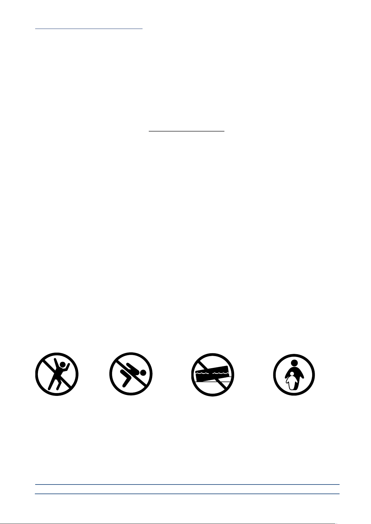
No diving
No jumping
No sloping ground
Use only under competent supervision
Save these instructions

ACQUAMARINA POOL MANUAL pag. 5 / 21
www.cpa-piscine.it
Rev.00–18/11/20
1
2
7
9
8
3
6
14
13
12
18
17
16
15
23
28
26
19 11
10
24
25
20
27
22
21
29
30
31
32
33
34
35
36
37
4
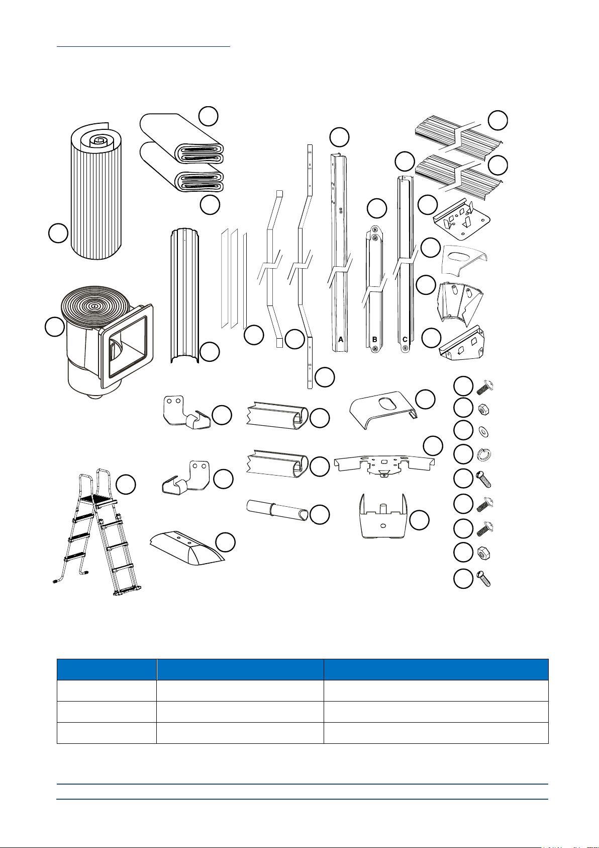
A horizontal side beam
B angled side beam
C vertical side beam
Components
Item No.
Description
Pool dimension (mm)
8011030 - 8011034
Acquamarina 490
L4900 x W3600 x H1200
8011031 - 8011035
Acquamarina 610
L6100 x W3600 x H1200
8011032 - 8011036
Acquamarina 730
L7300 x W3600 x H1200
Note:
•Check all parts and ensure they are present and undamaged before assembly.
•Report missing or damaged parts immediately to have them replaced.
•Images and objects may differ
Pool wall
Pool liner
Ground sheet
Skimmer
Note: for parts list
please refer to the
skimmer box manual
Ladder
Pool wall
vertical support
Self
adhesive
tape
PVC sleeve
Steel beam
Side bottom
metal piece A
Side bottom
metal piece B
Inside bottom
protector
Rail
Side rail A
Side rail B
Rail connector
Side upper joint
protector
Side top metal piece
Side bottom
joint protector
Top platform
Side top platform A
Side top platform B
Top metal piece
Upper joint
protector
Bottom metal piece
Bottom joint
protector
M6 x 11 - bolt
M6 - nut
M6 - washer
M6 –spring washer
ST4.2 x 13 - screw
M4 x 10 - bolt
M8 x 20 - bolt
M8 - nut
ST6.3 x 19 - screw

ACQUAMARINA POOL MANUAL pag. 6 / 21
www.cpa-piscine.it
Rev.00–18/11/20
No.
Description
Acquamarina pool 490
8011030 - 8011034
Acquamarina pool 610
8011031 - 8011035
Acquamarina pool 730
8011032 - 8011036
1
Pool wall
1
1
1
2
Pool liner
1
1
1
3
Leaf skimmer
1
1
1
4
Ground sheet
1
1
1
5
Pool cover
1
1
1
6
Ladder
1
1
1
7
Horizontal side beam
2
4
6
8
Vertical side beam
2
4
6
9
Angled side beam
2
4
6
10
Steel belt
1
2
3
11
Pvc sleeve
1
2
3
12
Side bottom metal piece A
2
4
6
13
Side bottom metal piece B
2
4
6
14
Inside bottom protector
2
4
6
15
Side bottom joint protector
2
4
6
16
Rail
1375mm length
12
12
12
Rail
1420mm length
0
0
0
17
Side rail A
1300mm length
8
8
8
Side rail A
1420mm length
0
0
0
Side rail B
1155mm length
0
4
8
Side rail B
1420mm length
0
0
0
18
Rail connector
32
32
32
19
Self adhesive tape
1
1
1
20
Top metal piece
8
8
8
21
Bottom metal piece
8
8
8
22
Bottom joint protector
8
8
8
23
Side top metal piece
2
4
6
24
Top platform
1380mm length
6
6
6
Top platform
1415mm length
0
0
0
25
Side top platform A
1332mm length
4
4
4
Side top platform A
1465mm length
0
0
0
Side top platform B
1235mm length
0
2
4
Side top platform B
1500mm length
0
0
0
26
Pool wall vertical support
8
8
8
27
Upper joint protector
8
8
8
28
Side upper joint protector
2
4
6
29
M6 x 11 –bolt
73
89
105
30
M6 –nut
57
57
57
31
M6 –washer
65
73
81
32
M6 –spring washer
40
48
56
33
ST4.2 x 13 - screw
36
40
44

ACQUAMARINA POOL MANUAL pag. 7 / 21
www.cpa-piscine.it
Rev.00–18/11/20
PHASE 1 –Selecting a suitable site
Carefully select the site for your new pool. This is the most important decision you will have to make to ensure the safety
and success of your pool construction. An incorrect site could cause problems in the future that may cause injury, death or
financial loss.
Read carefully the check list set out below when selecting your site.
TOOLS REQUIRED
•Phillips head screw driver
•Small shifter
•Clothes pegs
•Sharp knife
•Spirit level
•Site excavation tools
•Protective gloves
ACCEPTABLE
Flat, level, firm and dry ground with easy access to all sides of the pool exposed to direct sunlight, preferably in the morn ing.
Safe access to electricity for running the filter pump and other pool accessories. Access to main water source.
Protection from wind.
NOT ACCEPTABLE
•sloping ground
•concrete, asphalt, sandy gravel and swampy ground
•close to wooden construction e.g. pergola’s and
decking
•next to deciduous or leafy trees
•over-head wires and clothes line
•drains, electric wires or gas pipelines underneath
the site
•poor or little drainage or high flood risk locations
•high wind conditions
34
M4 x 10 - bolt
54
60
66
35
M8 x 20 - bolt
20
40
60
36
M8 - nut
20
40
60
37
ST6.3 x 19 - screw
4
8
12

ACQUAMARINA POOL MANUAL pag. 8 / 21
www.cpa-piscine.it
Rev.00–18/11/20
PHASE 2 –Pool setup
I. Ground preparation
The preparation of the ground is the most important step in the installation of the pool.
Mark off your pool area by driving stakes. Have a helper hold a tape measure or a string and mark off the pool perimeter using flour
or chalk. Remove sod inside the pool area to a distance of 30 cm beyond dimensions shown in the plot layout around entire
perimeter of pool.
Diagram 1 Diagram 2
Diagram 3 Diagram 4

ACQUAMARINA POOL MANUAL pag. 9 / 21
www.cpa-piscine.it
Rev.00–18/11/20
II. Levelling the area
WARNING
Levelling is extremely important: take as much time as possible to work out a site that is completely firm and levelled. Use
a carpenter’s level and straight edge to ensure that the site is completely level, flat and firm (see diagram 5). The pool
contains a huge amount of water and thousands of kilos of weight. Should the pool collapse due to unlevelled ground, it
could cause a lot of damage to property and even human injury or death!
Diagram 5
Remove the higher ground rather than filling the low laying ground (see diagram 6).
WARNING
Always remove grass and stones within the circle. Use ground sheet to ensure that the grass doesn’t penetrate the pool
liner and cause damage.
Diagram 6
Spread a light layer of fine brick layers sand over the foundation area. Level this layer evenly (see diagram 7). Once the site
has been cleared and levelled, it is time to start assembling the frame assembly.
Diagram 7
remove high spots
do not fill low spots

ACQUAMARINA POOL MANUAL pag. 10 / 21
www.cpa-piscine.it
Rev.00–18/11/20
III. Pool frame assembly
The pool wall side frame support consists of a left and right frame connected by a stainless steel belt (see diagram 8) .
Diagram 8
Outside
of pool
Left frame
Stainless steel belt
Right frame
Side bottom
joint protector
1. Connect the side bottom joint
protector to the top of the
vertical side beam
4. Connect the angled side beam
to the vertical side beam
2. Connect the lower end of the
angled side beam to the
horizontal side beam
3. Connect the lower end of
the vertical side beam to the
horizontal side beam
Diagram 9
Diagram 10
Diagram 11
Diagram 12
Connect both side
bottom metal piece A
and B to the horizontal
side beam
Vertical side beam
Angled side beam
Horizontal side beam
Side bottom
metal piece A
Side bottom
metal piece B

ACQUAMARINA POOL MANUAL pag. 11 / 21
www.cpa-piscine.it
Rev.00–18/11/20
1. Connect the steel belt to either end of the left and right side pool frames (see diagram 13 and 14). Make sure the steel
belt is protected by the PVC sleeve which is provided in the package. This will protect the pool liner from damage.
IV. Pool wall rail and rail connector setup
1. Position the left and right side wall frame in the middle of the prepared area (see diagram 15)
2. Place the rails around the area where the pool wall is to be installed (see diagram 15)
3. Connect the rails together using 2 rail connectors per rail (see diagram 16) and leave a 1.5 cm gap between each
connection (see diagram 17)
4. Connect the side tails to the side bottom metal piece A and B either side of the pool wall frame supports (see diagram
18)
Left frame
Diagram 13
Right frame
Diagram 14
Diagram 16
Diagram 17
Diagram 18
Diagram 15

ACQUAMARINA POOL MANUAL pag. 12 / 21
www.cpa-piscine.it
Rev.00–18/11/20
5. Place the bottom metal piece between the joins of the rails with the triangular end pointing out from the pool wall (diagram
19).
6. Place the inside bottom protector
over the steel belt and screw into
the horizontal side beam.
Note: ensure the PVC sleeve covers
the steel belt to prevent damage or
rust effecting the pool (diagram 20)
CAUTION: Wear protective gloves when handling metal wall
7. Place the metal pool wall with the skimmer hole at the
top, onto a piece of cardboard, ply wood or ground
during installation. Note: Position the pool wall’s
skimmer cutout in the same location to where your
electricity supply will be to power the filtration system
(diagram 21)
Diagram 21
8. Rest the end of the pool wall in the side bottom metal piece between the gap in the side rail. Make sure the prepared
location is not prone to constant windy conditions. Continue unrolling and placing the bottom edge of the pool wall into
the rails until the full length of the wall is sitting in rails (see diagram 22).
Diagram 20
Diagram 19
Inside of pool
Outside of pool
Leaf skimmer cut
out
Diagram 22

ACQUAMARINA POOL MANUAL pag. 13 / 21
www.cpa-piscine.it
Rev.00–18/11/20
9. On the opposite side of the pool wall, carefully lift and place the steel wall in between the side support frame and the
inside bottom protector.
Note: There is a section cut out of the pool wall that will allow the wall to slot over the horizontal support beam (see
diagram 23).
10. Line up the two ends of the pool wall then begin inserting and hand tightening each bolt and nut until the full length of the
join is assembled (see diagram 24). Do not completely tighten bolts before you check the wall is in the correct place,
level and that no damage has occurred to the pool wall.
Note: At this stage, it is recommended that you assemble the pool ladder to place over the pool wall to gain access to
the inside and outside of the pool area’s.
Diagram 24
Inside of pool
Inside of pool
Diagram 23

ACQUAMARINA POOL MANUAL pag. 14 / 21
www.cpa-piscine.it
Rev.00–18/11/20
V. Measuring the pool wall
WARNING
A pool that is not level is very dangerous and may
collapse at any time.
Diagram 25
Diagram 26
Check the pool wall level by placing a length of timber beam or similar across the diameter of the pool wall and placing the builders
level on the top of the timber beam (see diagram 25). If the deviation is more than 2 cm (see diagram 26) then the ground site
must be levelled again. Check also if the pool is oval and measure the diameter across a few spots to make sure the differences
of each diameter measured are within 2cm.
If the levels are not to specification then the area will have to be leveled again.
WARNING
Try not to manage any of the components when dissembling the pool wall to correct the level of the ground.
Once the measurements and levels are correct and all nuts and bolts are tightened, then cover the exposed screw heads with the
self-adhesive tape (see diagram 27 and 28).
Diagram 27 Diagram 28
15
Inside of pool
Outside of pool

ACQUAMARINA POOL MANUAL pag. 15 / 21
www.cpa-piscine.it
Rev.00–18/11/20
VI. Making a protective sand cushion at the foot of the inner pool
Diagram 29 Diagram 30
To protect the liner against the rail and the pool wall, it is recommended to create a protective covering made of fine brick sand at
the foot of the pool wall (see diagram 29 and 30). The size should be height 15 cm x width 15 cm so that it completely seals the
rail but doesn’t distort the pool liner.
VII. Fitting the PVC pool liner
Fit the PVC liner on a warm and sunny day, preferably above 22°C. Unfold the PVC liner and put it in the sun for 2 hours. This helps
to soften the PVC. If the temperature is below 16°C, the PVC liner will be hard and rigid and quite difficult to handle.
Put the liner at the center of the pool site inside the pool wall. Extend it evenly until the seam line reaches the base of the pool
where the protective sand cover is. Smooth out all the wrinkles in the liner. Straighten the PVC liner and hold it perpendicular to the
ground. Drape the pool liner over the pool wall.
There should be an overlap of 8 cm of the pool wall height (see diagram 31 and 32). Hold the overlap in place with clothes pegs.
Diagram 31 Diagram 32
Check if the pool liner is placed evenly around the perimeter. Evenly fold the excessive length of the PVC if you find it a bit loose.
Check if the overlap is uniform. If the pool liner is slightly short, then you will have to let it down and vice versa.
Fill the pool with 3 to 5 cm height of water to smooth out the liner against the pool wall (see diagram 31). Check to see if water is
level, if not, something is wrong and you will have to dismantle the liner and pool wall to access and level the ground area.
Sand cove
Sand cove
Base rail
Pool wall
Pool liner
Seam is centered
in the middle of
the sand cove

ACQUAMARINA POOL MANUAL pag. 16 / 21
www.cpa-piscine.it
Rev.00–18/11/20
Remove the pegs one at time whilst applying the fix rails (see diagram 33). Slide the pipe connectors into one end of the top rail,
then connect another top rail, continue around the circumference until all top rails are joined together and firmly pressed into the
top of the pool wall.
Diagram 33
Fix all top rails to the top of the pool wall and make sure they are all sitting properly.
CAUTION! Do not cut the excess overlap of
the pool liner wall. If you cut the overlap, it
will make the next pool installation difficult.
Rail

ACQUAMARINA POOL MANUAL pag. 17 / 21
www.cpa-piscine.it
Rev.00–18/11/20
VIII. Installing the top and side metal pieces
Hook the top metal pieces over the top rail between the rail connections and align with the bottom metal pieces (see diagram 34).
Place the side metal pieces over the top of the vertical side beams and rails and screw into place (see diagram 35).
Diagram 34
Diagram 35
Align top and
bottom metal pieces

ACQUAMARINA POOL MANUAL pag. 18 / 21
www.cpa-piscine.it
Rev.00–18/11/20
Place the two side top platforms on top of the rails and align the holes over the side top metal piece. Using four bolts, washers,
spring washers, attach the side top platforms to the side top metal piece and only hand tighten. Place a top platform at the end of
one of the side top platforms and attach using four bolts, washers, spring washers and nuts. Continue this process until all of the
top and side top platforms are attached to all of the top and side top metal pieces (see diagram 36, 37 and 38).
Check the alignment but do not tighten.
Diagram 36
Diagram 37
Diagram 38

ACQUAMARINA POOL MANUAL pag. 19 / 21
www.cpa-piscine.it
Rev.00–18/11/20
IX. Assembly of the vertical supports
Attach the bottom joint protector to the vertical support using the screws provided
(see diagram 39). Line up all of the screw holes of the vertical supports with the
top and bottom metal pieces. Fix the vertical support onto the top and bottom metal
pieces and hand screw into place. Continue this process around the pool until all of
the vertical supports are attached. Check and adjust the alignment of the vertical
supports to ensure that they are indeed vertical and straight then go around the pool
and tighten all screws top and bottom (see diagram 40).
X. Attaching joint protectors
Clip the non-screw end of the side joint protector over the side top platform join and screw the other end into place. Using the
same method, attach the joint protectors for the top platforms and screw into place. Do not over tighten! (See diagram 41 e 42)
Diagram 42
Diagram 41
Diagram 39
Diagram 40

ACQUAMARINA POOL MANUAL pag. 20 / 21
www.cpa-piscine.it
Rev.00–18/11/20
XI. Check all connections and joins
Once completed, check all connections and tighten loose screws and bolts but do not over tighten. Replace damaged components
and repair all tears, rips and holes with repair patch (see diagram 43).
Diagram 43
Side upper joint protector
Check for damaged or broken
protectors, replace where necessary
Upper joint protector
Check for damaged or broken
protectors, replace where
necessary
Pool liner
Check for rips, tears, holes
and repair where necessary
Vertical support
Check for damaged
supports and replace
where necessary
Bottom metal piece
Check for loose connections
and tighten screws and bolts
Bottom joint protector
top metal piece
Check for loose connections
and tighten screws and bolts
Top and bottom rails
Check to make sure the
pool wall is placed
firmly in between the
upper and lower rails
Top platform
Check for damaged or broken
platforms, repair where necessary
Vertical and side angle
beam connection
Check for loose
connections and tighten
screws and bolts
Bottom and side angle
beam connection
Check for loose
connections and tighten
screws and bolts
Side bottom and vertical
beam connection
Check for loose
connections and tighten
screws and bolts
Side A top platform
Check for damaged or broken
protectors, replace where
necessary
Side upper joint protector
Check for damaged or broken
protectors, replace where necessary
Upper joint protector
Check for damaged or
broken protectors, replace
where necessary
Pool liner
Check for rips, tears, holes
and repair where necessary
Vertical support
Check for damaged
supports and replace
where necessary
Bottom metal piece
Check for loose connections
and tighten screws and bolts
Bottom joint protector
top metal piece
Check for loose connections
and tighten screws and bolts
Top and bottom rails
Check to make sure the
pool wall is placed
firmly in between the
upper and lower rails
Top platform
Check for damaged or broken
platforms, repair where necessary
Side B top
platform
Check for
damaged or
broken
protectors,
replace where
necessary
Bottom and side angle
beam connection
Check for loose connections
and tighten screws and bolts
Side bottom and vertical
beam connection
Check for loose
connections and tighten
screws and bolts
Side A top platform
Check for damaged or broken
protectors, replace where
necessary
Vertical and side angle
beam connection
Check for loose
connections and tighten
screws and bolts
This manual suits for next models
9
Table of contents