CPcam CPN103 User manual

User
User’
’s Manual
s Manual
Video Web Server
Video Web Server
CPN103_V1.1
Please read instructions thoroughly before operation and retain
Please read instructions thoroughly before operation and retain it for future reference.
it for future reference.
2CH MJPEG VIDEO WEB SERVER
2CH MJPEG VIDEO WEB SERVER
25

Thank-You Note Before You Get Start
First of all, we would like to express our gratitude to you for purchasing this product.
This product is designed to meet your personal needs with our great industry-designing
ability and our everlasting perseverance to the quality of all our products.
This manual will introduce to you how to install this apparatus. Please keep it well for
your future reference.
Now, we would like to invite you to personally experience all of the powerful functions
this product offers.
Note: Firmware:
Firmware: Kernel: 1.0.1.0 AP application:
AP application: 1.0.4.3
Note: Any changes of the AP application, please refer to your distributor.
Note: Any changes of this manual made to the actual product are subjects to no further notification.

The lightning flash with arrowhead symbol, within an equilateral
triangle, is intended to alert the user to the presence of uninsulated
“dangerous voltage” within the product’s enclosure that may be of
sufficient magnitude to constitute a risk of electric shock to persons.
This exclamation point within an equilateral triangle is intended to
alert the user to the presence of important operating and
maintenance (servicing) instructions in the literature accompanying
the appliance.
CE Mark
This apparatus is manufactured to comply with the radio interference
requirements.
The company does not warrant that this manual will be uninterrupted or error-free.
We reserve the right to revise or remove any content in this manual at any time.
CAUTION:
CAUTION:
To reduce the risk of electric shock, do not expose this apparatus to rain or moisture.
Only operate this apparatus from the type of power source indicated on the label.
The company shall not be liable for any damages arising out of any improper use, even if we have
been advised of the possibility of such damages.
CAUTION
CAUTION
RISK OF ELECTRIC SHOCK
RISK OF ELECTRIC SHOCK
DO NO OPEN
DO NO OPEN
IMPORTANT SAFEGUARD
IMPORTANT SAFEGUARD

PARTS AND FEATURES
PARTS AND FEATURES
1.1 FEATURES ------------------------------------------------------------------------------------------------------------
1.2 PACKAGE CONTENTS --------------------------------------------------------------------------------------------
1.3 SPECIFICATION -----------------------------------------------------------------------------------------------------
1.4 PANEL ------------------------------------------------------------------------------------------------------------------
INSTALLATION AND CONNECTION
INSTALLATION AND CONNECTION
2.1 SYSTEM CONNECTION -------------------------------------------------------------------------------------------
2.2 CONNECT DVR TO VIDEO WEB SERVER ------------------------------------------------------------------
2.3 SOFTWARE INSTALLATION ------------------------------------------------------------------------------------
2.4 IP SETTING AND LAN CONNECTION ------------------------------------------------------------------------
2.5 CONNECT VIA INTERNET ---------------------------------------------------------------------------------------
OPERATION GUIDE
OPERATION GUIDE
3.1 SOFTWARE OPERATION -----------------------------------------------------------------------------------------
3.2 PLAYBACK OPERATION -----------------------------------------------------------------------------------------
3.3 ADVANCED SETTING ----------------------------------------------------------------------------------------------
Network ------------------------------------------------------------------------------------------------------------
DDNS ---------------------------------------------------------------------------------------------------------------
Mail -----------------------------------------------------------------------------------------------------------------
FTP ------------------------------------------------------------------------------------------------------------------
Server Time Config ---------------------------------------------------------------------------------------------
Alarm ----------------------------------------------------------------------------------------------------------------
Alarm List ----------------------------------------------------------------------------------------------------------
General -------------------------------------------------------------------------------------------------------------
Account ------------------------------------------------------------------------------------------------------------
Peripheral ----------------------------------------------------------------------------------------------------------
Online User Info -------------------------------------------------------------------------------------------------
File Path ------------------------------------------------------------------------------------------------------------
APPENDIX #1
APPENDIX #1 DVR PIN CONNECTION -------------------------------------------------------------
APPENDIX #2
APPENDIX #2 PTZ PIN CONNECTION --------------------------------------------------------------
APPENDIX #3
APPENDIX #3 IE BROWSER --------------------------------------------------------------------------
APPENDIX #4
APPENDIX #4 DDNS APPLY --------------------------------------------------------------------------
TABLE OF CONTENTS
TABLE OF CONTENTS
1
1
2
3
4
5
6
6
11
12
15
16
16
17
18
18
19
19
20
20
21
21
22
22
23
25
26
27

PARTS AND FEATURES
PARTS AND FEATURES
1.1 FEATURES
1.1 FEATURES
NOTE :
Please check the package contents to make sure that all accessories are included.
1
Network:
Network:
JPEG real time compression format
Support TCP/IP, PPPoE, DDNS and DHCP for network connection
Support DDNS function as a router
Alarm:
Alarm:
Support alarm trigger recording
Full alarm-triggered event list for easy search and quick playback
Whenever alarm system triggered,
video streaming or pictures will be uploaded over FTP, email as an instant
notification.
Network Viewing:
Network Viewing:
Support video access by APs (software) or HTML pages (IE explorer)
Support multiple user access levels with security protection
Support multiple on-line users (up to 5 users)
General:
General:
Support different PC OS
Video output: Up to 30(NTSC), 25(PAL) frames/ second
Support NTSC / PAL system
Support watch dog function
ANR will reactivate recording function automatically when network is
reconnected
Easy to upgrade firmware
1.2 PACKAGE CONTENTS
1.2 PACKAGE CONTENTS
Crossover Cable Adapter
Video Web Server Manual & Quick Start
Licensed Software AP

1.3 SPECIFICATION
1.3 SPECIFICATION
2
Design and specification are subject to change without notice.
Support TCP/IP, PPPoE, DDNS and DHCP for network connectionNetwork Connection
500 mA
Current consumption
DC 12V
Power Source
Password Protection
Security
Triggered by GPIO Input, Action: E-mail video/images or video/images
upload to FTP site's specific accounts
Trigger & Action
YesAlarm Trigger Recording
Video output: Up to 30(NTSC), 25(PAL) frames/ second
Performance
704x480, 352x240 (NTSC) / 704x576, 352x288 (PAL)
Resolution
TCP/IP, ICMP, SMTP, FTP, HTTP, DHCP, DDNS, PPPoE, SNTP
Protocols
Brightness, Contrast and Hue
Video Adjustment
JPEG
Image Compression
Ethernet (10/100 Base-T)
Network Interface
Yes
RS-485 Port
Yes
Watch dog
4 inputs / 2 outputs
Alarm Input
2 channel for analog & digital products, 1.0 Vp-p 75 composite, BNC
Video Input
CPN103
CPN103
Specification
Specification
1)
1) LAN:
LAN:
Connect Video Web Server to the Internet or LAN or connect directly to PC
(Use crossover cable or straight-through cable).
2)
2) VIDEO INPUT
VIDEO INPUT (2 channels):
Connect to video source, such as camera or DVR video output.
3)
3) ALARM I/O
ALARM I/O (optional for advanced applications):
Connect control devices, such as PTZ, DVR and external alarm signal input.
4)
4) POWER:
POWER:
Plug in the supplied power adaptor (12V / 500mA).
5)
5) RESET
RESET (at the bottom of Video Web Server):
Press this button to default setting.
1.4 PANEL
1.4 PANEL
3
Solder Side of DSUB 9 PIN
NO
COM

INSTALLATION AND CONNECTION
INSTALLATION AND CONNECTION
2.1 SYSTEM CONNECTION
2.1 SYSTEM CONNECTION
4
1)
1) Power:
Power: Connect to DC 12V regulated adapter.
2)
2) Video Input:
Video Input: Connect to video outputs of CAMERA or DVR…etc.
Take DVR as an example, after connection, set the baud rate and ID of the DVR. Make
sure that the baud rate and ID as same as the settings of the VIDEO WEB SERVER.
For more detailed instruction, please refer to “Section 2.2”.
3)
3) Software Installation:
Software Installation: Install the software on PC.
4)
4) IP Setting:
IP Setting: Connect PC with Video Web Server for IP setting (Local Connection).
5)
5) LAN:
LAN: After IP setting, connect Video Web Server with ADSL or CABLE MODEM.
6)
6) ALARM I/O
ALARM I/O (Optional for advanced applications)
(Optional for advanced applications) :
:
Connect to control devices, such as PTZ, DVR and external alarm signal input.
[ CONNECTION APPLICATIONS ]
[ CONNECTION APPLICATIONS ]
5
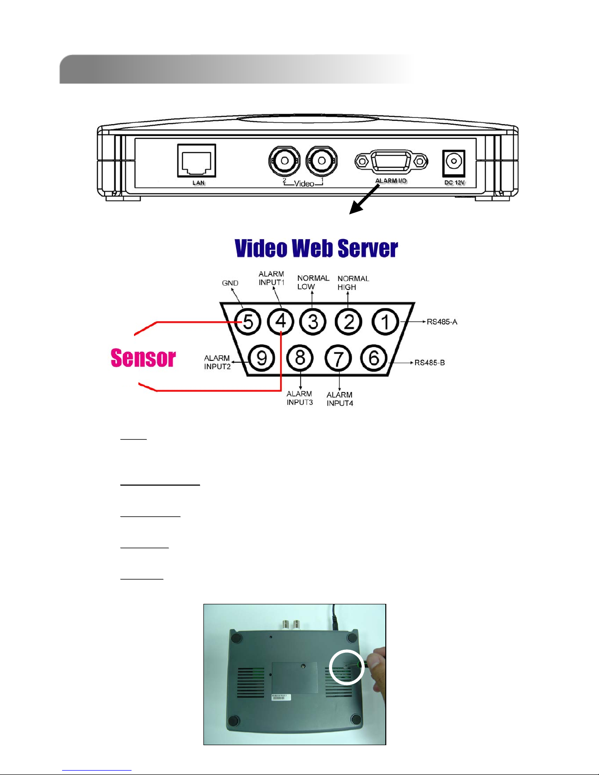
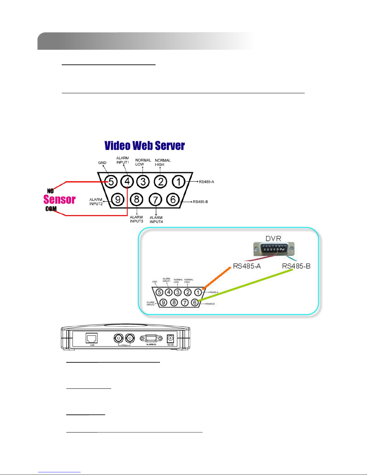
2.2 CONNECT DVR TO VIDEO WEB SERVER
2.2 CONNECT DVR TO VIDEO WEB SERVER
1)
1) DVR Baud Rate and ID Setting:
DVR Baud Rate and ID Setting:
Set the baud rate and ID of the DVR. Make sure that the baud rate and ID as same as the
settings of the VIDEO WEB SERVER (P.21 Peripheral).
2)
2) DVR and Video Web Server PIN Connections (Optional for advanced
DVR and Video Web Server PIN Connections (Optional for advanced application):
application):
Connect DVR PIN with VIDEO WEB SERVER PIN (For more detailed information, please
refer to APPENDIX #1 ).
For detailed PIN connection, please refer to “Appendix #2 ” and “Appendix #3”
PIN 1, 6:
PIN 1, 6: RS485-A, RS485-B
Use RS485-A & RS485-B serial communication signals to control digital units
just like that to control DVR.
PIN 4, 9, 8, 7:
PIN 4, 9, 8, 7: ALARM INPUT
Use PIN 4,,9, 8, 7 to receive the alarm input and then trigger Video Server to
send mail to users for auto e-mail warning system. .
PIN 5:
PIN 5: GND
Ground
PIN 2, 3:
PIN 2, 3: NORMAL HIGH, NORMAL LOW
Use PIN 2 or 3 to trigger external device to act.
Please see the example picture below for 1CH/4CH DVR.
It’s recommended to solder these joints
Solder Side of DSUB 9 PIN
2.3 SOFTWARE INSTALLATION
2.3 SOFTWARE INSTALLATION
2.4 IP SETTING AND LAN CONNECTION
2.4 IP SETTING AND LAN CONNECTION
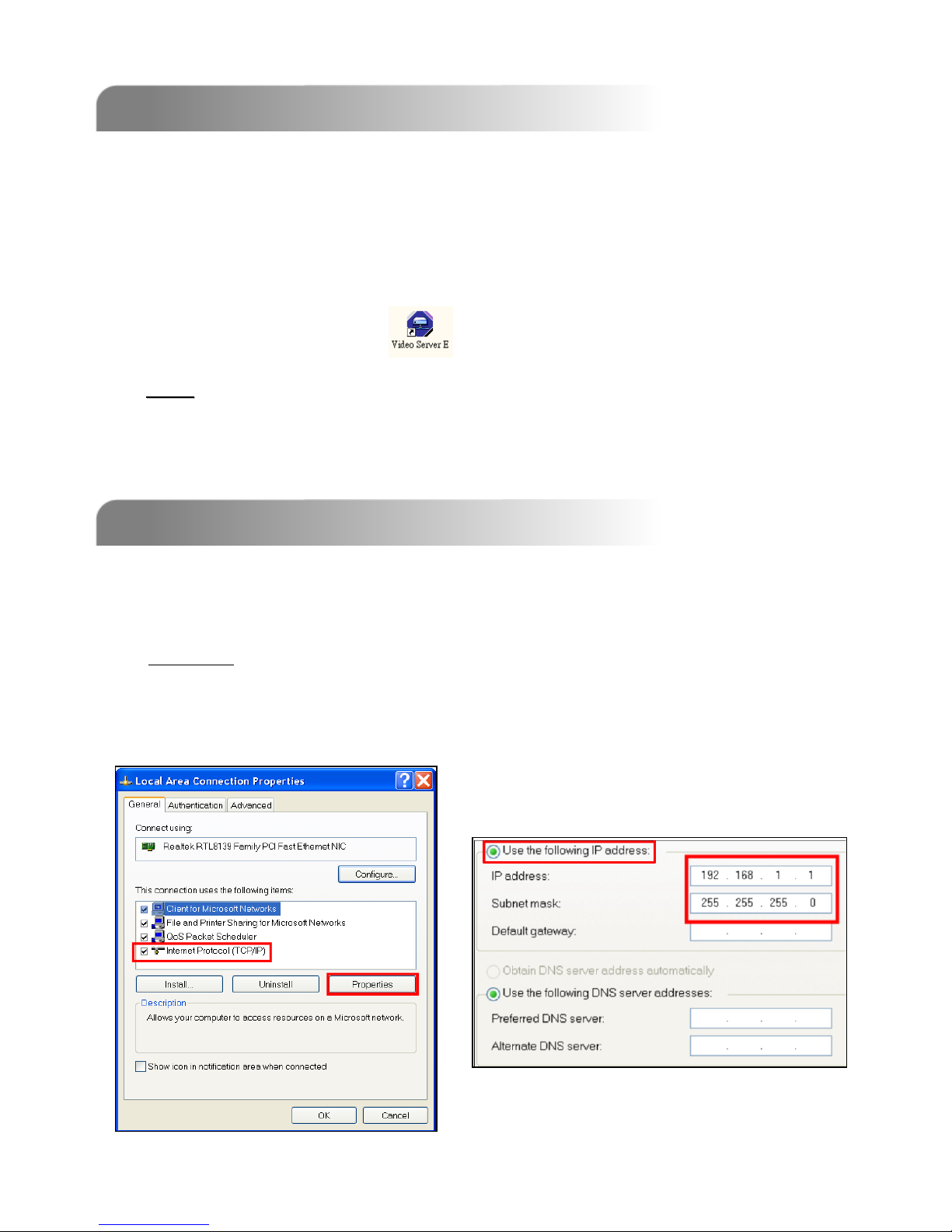
Step 1- 1:
Start ÆControl Panel ÆNetwork and Internet Connections ÆNetwork
Connections ÆLocal Area Connection Status ÆProperties ÆInternet Protocol
(TCP/IP).
1) Network setting for PC. (This following instruction is based on Win XP OS.
If the O/S is Win 2000, the setup procedure is similar to that on Win XP OS.)
6
Note:
Note:
After physical connection, please go to the next two sections for IP address settings.
1) Put the attached CD into a CD-ROM and it will start to install application
program into PC.
2) Click “Install Video Server“ to run the setup program.
3) Click “Finish” button to complete the setup.
And you will see the icon “ “ on the desktop.
Table of contents


