CPG G15 User manual

1
COUNTERTOP GRILL
Installaon and Operaon Instrucons
Model: G15, G24, G36, G48
G15T, G24T, G36T, G48T
IMPORTANT FOR FUTURE REFERENCE
Please complete this informaon and retain this manual for the life of the equipment. For
Warranty Service and/or parts, this informaon is required.
Model Number Serial Number Date Purchased
WARNING: For your safety, do not store or use gasoline or other flammable vapors or
liquids in the vicinity of this or any other appliances. Keep the area free and clear of
combusble materials. (See ANSI Z83. 14B, 1991).
WARNING:Improper installaon, adjustment, alteraon, service or maintenance can
cause property damage, injury, or death. Read the installaon, operang and
maintenance instrucons thoroughly before installing, or servicing this equipment.
WARNING:Instrucons must be posted in a prominent locaon. All safety precauons
must be taken in the event the user smells gas. Safety informaon can be obtained from
your local gas supplier.
CAUTION: These models are designed, built, and sold for commercial use only. If these
models are posioned so the general public can use the equipment, make sure that
cauons, warnings, and operang instrucons are clearly posted near each unit so that
anyone using the equipment will use it correctly and not injure themselves or harm the
equipment.
GAS PRESSURE
The appliance and it’s individual shutoffvalve (to be supplied by user) must be disconnected from
the gas supply piping system during any pressure tesng of that system at test pressures in excess
of ½ psi (3.45 kPa).
The appliance must be isolated from the gas supply piping system by closing it’s individual manual
shut-offvalve during any pressure tesng of the gas supply piping system at test pressures equal to
or less than ½ psi (3.45 kPa).
WARNING:A factory authorized agent should handle all maintenance and repair. Before
doing any maintenance or repair, contact your authorized service representave.
Conforms to ANSI STD
Z83.11b-2009(R2012)
Certified to CSA
STD 1.8b-2009(R2012)

2
Congratulations on your purchase of Cooking Performance Group commercial cooking equipment.
Cooking Performance Group takes pride in the design and quality of our products. When used as
intended and with proper care and maintenance, you will experience years of reliable operation
from this equipment. To ensure best results, it is important that you read and follow the
instructions in this manual carefully.
TABLE OF CONTENTS:
ITEM PAGE ITEM PAGE
Safety precautions 3 Cleaning & Maintenance 8
General Installation Instructions
4
Troubleshooting 9
Specifications & Dimensions 4 Explosion View Drawing 10, 12
Conversion 5 Spare Part List
Limited Warranty
10, 13, 14
15
Lighting Instructions
6
Operating Instructions 8

3
LOCATION OF DATA PLATE
The data plate is located on the side panel.
IMMEDIATELY INSPECT FOR SHIPPING DAMAGE
All equipment should be examined for damage before and during unloading. The freight carrier
has assumed responsibility for its safe transit and delivery. If equipment is received damaged,
either apparent or concealed, a claim must be made with the delivering carrier.
A) Apparent damage or loss must be noted on the freight bill at the time of delivery. It must then
be signed by the carrier representative (Driver). If this is not done, the carrier may refuse the claim.
The carrier can supply the necessary forms.
B) If concealed damage is not apparent until after equipment is uncrated, a request for inspection
must be made to the carrier within 15 days. The carrier should arrange an inspection. Be certain to
hold all contents and packaging material.
Installation and service should be performed by a qualified installer who thoroughly reads,
understands and follows these instructions.
If you have questions concerning the installation, operation, maintenance or service of this
product, visit Cooking Performance Group’s website at www.CookingPerformanceGroup.com.
SAFETY PRECAUTIONS
DANGER
:
This symbol warns of imminent hazard which will result in serious injury or
death.
WARNING: This symbol refers to a potential hazard or unsafe practice, which could result
in serious injury or death.
CAUTION: This symbol refers to a potential hazard or unsafe practice, which could result
in minor or moderate injury or product or property damage.
NOTICE: This symbol refers to information that needs special attention or must be fully
understood even though not dangerous.
NOTICE: This product is intended for commercial use only. Not for household use.
NOTICE: Local codes regarding installation vary greatly from one area to another. The National Fire
Protection Association, Inc., states in its NFPA96 latest edition that local codes are
“Authority Having Jurisdiction” when it comes to requirement for installation of
equipment. Therefore, installation should comply with all local codes.

4
GENERAL INSTALLATION INSTRUCTIONS
Ensure gas supply and gas type, as shown on unit nameplate, agree.
Unit installaon must conform with the Naonal Fuel Gas Code, ANSI Z223.1/NFPA 54, the
Naonal Gas Installaon Code, CSA-B149.1, or the Propane Installaon Code, CSA-B149.2 as
applicable and in accordance with local codes.
Screw legs into the permanently fastened nuts on the four corners of the unit and ghten by hand.
Level the unit by turning the adjustment screw at the boom of each leg. Do not slide unit with
legs mounted, liif necessary to move unit.
Pipe threading compound must be resistant to the acon of liquefied petroleum gases.
Cauon: DO NOT use an open flame to check for leaks. Check all gas piping for leaks with a soap
and water soluon before operang unit.
THESE UNITS ARE SUITABLE FOR INSTALLATION ON NON-COMBUSTIBLE SURFACES ONLY.
Combusble clearances:
6" sides (152 mm) 6" rear (152 mm) 4" floor (102 mm)
Noncombusble clearances:
0" sides ( 0 mm) 0" rear ( 0 mm) 4" floor (102 mm)
Do not obstruct the flow of combuson and venlaon air under the unit by the legs or behind
the unit by the flue.
Adequate clearance for air openings into the combuson chamber is required. Do not place
objects between the boom of the unit and the counter top.
There must be adequate clearance for removal of the front panel. All major parts except the
burners are removable thru the front if the gas line is disconnected.
SPECIFICATIONS AND DIMENSIONS
MODEL WIDTH
IN. (MM)
DEPTH
IN. (MM)
HEIGHT
IN. (MM)
# OF
BURNERS
BTU/PER
NAT/LP
TOTAL
BTU/Hr
Pressure
In.w.c
G15
G15T 15(381) 26.8(680) 16.3(415) 1 30,000 30,000 6/10
G24
G24T 24(610) 26.8(680) 16.3(415) 2 30,000 60,000 6/10
G36
G36T 36(915) 26.8(680) 16.3(415) 3 30,000 90,000 6/10
G48
G48T 48(1220) 26.8(680) 16.3(415) 4 30,000 12,0000 6/10
Note: regulator – 75mm/3.25 inch depth. Dimensions above do not include regulator.
Griddle Surface Dimensions
MODEL
WIDTH IN. (MM)
DEPTH IN. (MM)
G15
G15T 15(377) 20(510)
G24
G24T 24(606) 20(510)
G36
G36T 36(911) 20(510)
G48
G48T 48(1216 ) 20(510)

5
CONVERSION (Manual Control)
These instructions are for the conversion from Natural Gas to Propane (L.P.) on all models. The
conversion should be done before connecting the unit to the gas supply.
Units are shipped from the factory equipped for use on natural gas. Orifices necessary for LP
(propane) are provided in a bag tied to the valve on the front panel.
1.
Remove
the
knobs
and
front
panel.
2
.
Uns
2. Unscrew bolts and pilot valve,
then remove the manifold.
1.
Remove the knobs and front
panel.
Note: Unit Number on side
of orifice fittings.
Plastic Insert
3. Replace the orifice
fittings into the valve.
4. Install the front panel
knobs
5. Before installing the regulator,
unscrew the octagonal cap, up you can
read (NAT) on the plastic insert out of
the cap, flip it over and snap back in
place. You can now read (L.P).
6. Continue with
installation.
Regulator with brass cap L.P Position of insert

6
LIGHTING INSTRUCTIONS (Manual Control)
Lighting pilot
(For G15, G24, G36, G48 Models)
The pilot light on the appliance has been set at the factory. A screwdriver may be required for the
first lighting to adjust the flame for your elevation.
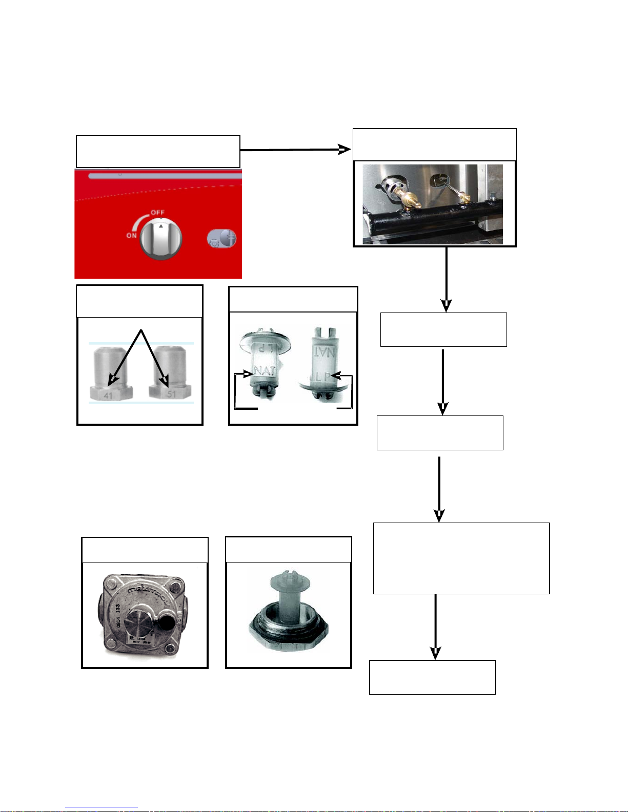
1. Turn off the manual valve and wait 5 minutes to clear the gas.
2. Turn all knobs to the "OFF" position.
3. Hold an ignition source (match) at the pilot. When the flame is established, remove the
ignition source.
4. Turn the burner knobs to "ON". If the burner does not ignite, promptly open the pilot valve
more. If the pilot flame appears larger than necessary, turn it down and reset burner ignition. The
pilot flame should be as small as possible but large enough to guarantee reliable ignition of the
burners when the knobs are turned to "ON".
Lighting main burner
(For G15, G24, G36, G48 Models)
To light burner, turn knob to “ON.” Then adjust to the desired flame level. The range of adjustment
is virtually infinite between “ON” and “OFF”.
Main burner air supply:
1. For efficient burner operation, a proper balance of gas volume and primary air supply must be
maintained which will result in complete combustion. Insufficient air supply results in a yellow
streaming flame. Primary air supply is controlled by an air shutter on the front of the burner.
2. Loosen the screws on the front of the burner and adjust the air shutter to just eliminate the
yellow tips of the burner flame. Lock the air shutter in place by tightening the screws.
Lighting the Main Burners
(For G15T, G24T, G36T, G48T Models)
These Griddles are fitted with individual standing pilots for each burner.
Flame Failure Protection is incorporated for each burner by way of a thermo-electric system which
will shut off the gas supply to that burner in the event that the burner goes out, so that un-burnt
gas is not expelled.
a. Select the burner required, depress and turn the corresponding gas control knob anti-clockwise
to the ‘PILOT’ position.
b. With the gas control knob depressed, manually light the pilot burner.
c. Release the gas control knob after approximately 10-20 seconds after lighting the pilot burner.
d. The pilot burner should stay alight - if not, repeat Steps (b. to c. above.)
e. Rotate the gas control knob anti-clockwise to the desired temperature mark.
f. The main burner will be now ignited automatically.

7
Turning 'OFF' the Main Burners / Pilots
(For G15T, G24T, G36T, G48T Models)
a. To turn 'OFF' the main burner, but keep the pilot burner lit, rotate the gas control knob to the
'PILOT' position. The main burner will extinguish and the pilot will remain lit.
b. To turn 'OFF' the 'PILOT', depress and turn the gas control knob clockwise back to the ‘OFF’
position. The 'PILOT' burner will extinguish.
Note:
Please wait at least 15 seconds to restart the main burners to maintain the best function of the
thermostat valve after turning off the main burners.
CAUTION
All burners are lit from constantly burning pilots. Turning the valve to the desired flame height is
all that is required to put the unit in service.
Do not permit fans to blow directly at the unit. Wherever possible, avoid open windows next to
the units' sides or back. Avoid wall type fans which create air cross-currents within a room.
It is also necessary that sufficient air should be allowed to enter the room to compensate for the
amount of air removed by any ventilating system. Otherwise, a subnormal atmospheric pressure
will occur, affecting operation and causing undesirable working conditions.
A properly designed and installed hood will act as the heart of the ventilating system for the room
or area in which the unit is installed, and will leave the unit independent of changing draft
conditions.
All valves must be checked and lubricated periodically. This must be done by an authorized service
representative in your area.

8
OPERATION INSTRUCTIONS
SEASON GRIDDLE:
Heat to low temperature (300 - 350 F/150-180C) and pour on a small amount of cooking oil, about
one ounce (30cc) per square foot of surface. Spread the oil over the entire griddle surface with a
cloth to create a thin film. Wipe off any excess oil with a cloth. Repeat this procedure 2 to 3 times
until the griddle has a slick, mirror-like surface.
OPERATION:
Turn the burners on about 15-20 minutes before cooking for preheating. Set the knobs to the
desired flame height or temperature. Each valve will control the gas flow to the burner to bring
that area of the unit up to the set temperature. If different temperature settings are to be used,
adjoining areas should be set at progressively higher temperatures using the lowest temperatures
on the outside burners. A uniform and systematic approach to the loading of the unit will produce
the most consistent product results.
CLEANING & MAINTENANCE
INITIAL CLEANING:
Prior to operating your new griddle, thoroughly wash the griddle surface and the exterior with a
mild detergent or soap solution. Do not use abrasive cleaners since this might damage the cabinet
finish. If the stainless steel surfaces become discolored, scrub by rubbing only in the direction of
the finished grain.
DAILY CLEANING:
1. Always turn unit off and allow it to cool completely before cleaning. Clean thoroughly before
first use.
2. After each use, clean the griddle with wire brush or flexible spatula.
3. Once a day, thoroughly clean back splash, sides and front. Remove the grease drawer, empty
it and wash it out.
4. Once a week, clean the griddle surface thoroughly. If necessary, use a griddle stone, wire
brush or steel wool on the surface. Rub with the grain of the metal while the griddle is
still warm. A detergent may be used on the plate surface to help clean it; but, care must be
taken to be sure the detergent is thoroughly removed. After removal of the detergent, the
surface of the plate should then be covered with a thin film of oil to prevent rusting. Clean
stainless surfaces with a damp cloth and polish with a soft dry cloth. To remove
discoloration, use a nonabrasive cleaner. After each "weekly" cleaning, the griddle must be
seasoned again. If the griddle usage is very high, the "weekly" cleaning procedures may be
done more often than once a week.
NOTE: Parts protected by the manufacturer or his agent are not to be adjusted by the installer,
unless the installer is an authorized service agent.

9
TOUBLESHOOTING GUIDE
PROBLEM POSSIBLE CAUSE
Pilot burner cannot be lit.
The pilot valve is obstructed.
Pilot gas turned off pilot valve.
The pilot valve is bad.
Fat appears to smoke excessively. Griddle plate is too hot.
Moisture in the food may be turning into steam.
Food sticks to griddle.
Griddle plate is too hot.
Griddle surface needs cleaning and/or seasoning.
Surface under food may not have been covered with enough
cooking oil.
Food burned around edges or contains dark
specks.
Griddle plate is too hot.
Griddle surface needs cleaning and/or seasoning.
Surface under food may not have been covered with enough
cooking oil.
Food is undercooked inside.
Griddle plate is too hot
Food may not have been cooked for long enough time.
Food tastes greasy or has objectionable
off-flavor.
Griddle plate is too hot.
Food may have been stored improperly before cooking.
Too much griddle fat used.
Noticeable build-up of gum on griddle.
Griddle plate is too hot.
Griddle surface needs cleaning and/or seasoning.
Too much griddle fat used.

10
EXPLOSION VIEW DRAWING
MODEL: G24

11
Spare Parts List
NO.
DESCRIPTION
MODEL
CODE
QTY
1Stainless steel
Burner Assy. “u” shape
G15
06.05.1470672
1
G24 2
G36 3
G48 4
2
G15
01.22.1069501 1
G24
G36
G48
3 Tray
G15
01.05.1029395
1
G24
01.05.1029318
G36
G48
4 Adjustable Foot
G15
01.02.1005373 4
G24
G36
G48
5 Manifold
G15 01.24.1070937
1
G24 01.24.1070931
G36 01.24.1070934
G48 01.24.1070936
6 Pilot Pipe
G15
06.05.1472152
1
G24 2
G36
3
G48
4
7 Pilot Valve
G15
01.20.1068509
1
G24 2
G36 3
G48 4
8 Valve For Manual
G15
01.20.1068502
1
G24 2
G36 3
G48 4
9
Orifice 41#NG
G15
01.20.1068641
1
G24 2
G36 3
G48 4
Orifice 51#LPG
G15
01.20.1068651
1
G24 2
G36 3
G48
4
10 Dial
G15
01.02.1005392
1
G24 2
G36
3
G48
4
Regulator 6”-NAT or
10"-LP, 3/4" -PT

12
MODEL: G24T

13
Spare Parts List
NO.
DESCRIPTION
MODEL
CODE
QTY
1Stainless steel
Burner Assy. “u” shape
G15T
06.05.1470672
1
G24T 2
G36T 3
G48T 4
2
G15T
01.22.1069501 1
G24T
G36T
G48T
3Flame device system
(No injector included)
G15T
01.22.1069542
1
G24T 2
G36T 3
G48T 4
4
ODS injector-0.45 NG
G15T
01.20.1068513
1
G24T 2
G36T 3
G48T 4
ODS injector-0.25 LPG
G15T
01.20.1068512
1
G24T 2
G36T
3
G48T 4
5 Tray
G15T
01.05.1029395
1
G24T
01.05.1029318
G36T
G48T
6 Adjustable Foot
G15T
01.02.1005373 4
G24T
G36T
G48T
7 Thermostatic Valve
G15T
01.20.1068510
1
G24T 2
G36T 3
G48T 4
8 Main Pipe assy.
G15T
06.05.1472204
1
G24T
2
G36T
3
G48T
4
9 Pilot pipe
G15T
06.05.1472205
1
G24T 2
G36T 3
G48T 4
10
Orifice 41#NG
G15T
01.20.1068641
1
G24T 2
G36T 3
G48T 4
Orifice 51#LPG
G15T
01.20.1068651
1
G24T 2
G36T
3
G48T
4
Regulator 6”-NAT or
10"-LP, 3/4" -PT

14
11 Dial
G15T
01.02.1005392
1
G24T 2
G36T 3
G48T 4
Cooking Performance Group
Lancaster, Pennsylvania
Wbsite: www.cookingperformancegroup.co

15
Limited Warranty
Cooking Performance Group Cooking Equipment Models:
Griddles: G15, G24, G36, G48, G15T, G24T, G36T, G48T
Charbroilers: CBL15, CBL24, CBL36, CBL48, CBR15, CBR24, CBR36, CBR48
Hot Plates: HP212, HP424, HP636
Fryers: CF15, CF30
All new Cooking Performance Group Griddles, Charbroilers, Hot Plates, and Fryers used for
commercial purpose are warranted against defects in materials and workmanship under normal use
and maintenance. The Warranty runs for one year from the date of original installaon and is for
the benefit of the original purchaser only. All other warranes, expressed or implied, statutory or
otherwise, including without limitaon any implied warranty of merchantability for fitness for
purposes are excluded. The seller shall in no event be liable for direct, indirect or consequenal
damages in connecon with Cooking Performance Group commercial products.
Exclusions
The following condions are not covered by warranty:
•Equipment damage or equipment failure occurs because of accident, carelessness, lack of
proper set-up, supervision when required, or if the equipment is installed or operated in any
manner contrary to the installaon and operang instrucons.
•Equipment damage or equipment failure due to improper installaon, improper ulity
connecon or supply, and problems due to venlaon.
•Equipment that has not been used appropriately, or has been subject to misuse, neglect,
abuse, accident, alteraon, negligence, damage during transit, delivery or installaon, fire,
flood, or act of God.
•Equipment that has the model number or serial number removed or altered.
•Equipment that has been changed, altered, or modified or repaired by other than an
Authorized Service Agency. Cooking Performance Group shall not be held liable for any
damages to any person or property which may result from the use of the equipment
thereaer.
This warranty does not apply to, and Cooking Performance Group is not responsible for any
warranty claims on products sold or used outside of the conguous United States.
This equipment is intended for commercial use only. Warranty is void if equipment is installed in
other than commercial applicaons.
This manual suits for next models
7
Table of contents
Other CPG Grill manuals