CPG PowerTone ASHP User manual

Model ASHP
PowerTone® Amplified Speaker
(With or without Strobe Warning Light)
-1 -
document rev
256880
E
0608
COMMERCIAL PRODUCTS GROUP
2519-4th Ave, Moline, IL 61265
800.521.8219 : 800.225.4109
www.cpglifesafety.com
SAFETY MESSAGE
People's lives depend on your safe installation, test, operation, and
maintenance of our products. Read, understand, and follow all safety
messages and instructions. Refer to "Safety Messages for Equipment
Used in Fire-Protective Signaling Systems" and any other documentation
shipped with equipment before performing any system related duty.
GENERAL.
This PowerTone Model ASHP is a continuous duty, polarized,
indoor/outdoor rated, high output (with internal volume adjustment),
amplified speaker for use with fire alarm systems. It is suitable for use in
areas with high ambient noise levels that require a loud distinctive signal.
Any one of ten plug-in tone cards (purchased separately) may be used
(see table 2). In addition, one of two available Model PTCK plug-in
connector cards can be used. The Model PTCK plug-in connector cards
will allow use of externally generated tone or voice signals (see table 2)
from a remote audio amplifier, such as CPG’s PowerTone System.
The PowerTone Model ASHP is available with an optional strobe light
attached to the 24Vdc units. For additional information regarding the
attached strobe and message label(s) attachment, refer to Model V1971
strobe instruction sheet (Part No. 2561088 or 2561090) or Model VST
strobe instruction sheet (Part No. 2561310). Model V1971 may be used
outdoors when Model VW outdoor kit is employed; otherwise, Model
V1971 is for indoor use only. Model VST may be used for indoor use
only. The speaker projector is adjustable and may be repositioned to
obtain desired sound distribution.
INSTALLATION.
Unpacking
After unpacking the amplified speaker, examine it carefully for possible
damage that may have occurred in transit. If equipment has been
damaged, immediately file a claim with carrier stating extent of damage.
Carefully check all shipping labels and tags for special instructions before
removing or destroying them.
Mounting Arrangements
The amplified speaker can be mounted on any relatively flat surface.
Conduit connections can be made to two 1/2" threaded openings at the
bottom of the housing or to 7/8" knockout in rear of housing. A 1/2"
conduit plug is supplied for field installation if one of the 1/2" threaded
openings is not utilized. After the mounting location and mounting method
have been selected, proceed with the applicable instructions below (see
figure 1).
WARNING
Property damage, serious injury, or death could occur if an accumulation
of water, snow, dust, etc. resides in the speaker projector, severely
reducing or preventing operation of this device. Mount the unit so speaker
projector is pointed horizontally or slightly downward.
1. Flat Surface Mounting
a. Remove and retain the two screws that secure cover to
housing. Remove the cover.
WARNING
Property damage, serious injury, or death could occur if any objects are in
front of speaker, severely reducing optimum sound distribution. For
maximum effectiveness, ensure that the front of the speaker is clear of
obstructions.
b. Select the mounting location and place rear of housing against
mounting surface.
c. Using the mounting holes (two (2) inside the housing) as a
template, scribe drill position marks on the mounting surface.
See figure 1 for mounting hole locations and dimensions.
WARNING
Before drilling holes in any surface, ensure that both sides of surface are
clear of items that could be damaged.
d. Secure the unit to a wooden mounting surface with #10 x 1"
wood screws. If mounting on a metal surface, drill 13/64"
diameter holes and secure the unit with #10 screws,
lockwashers and nuts. Route power and supervision leads
through the conduit to the audible signal. Install a 1/2" electrical
connector at the bottom of the audible signal. Route wires
through conduit and electrical connector into the audible signal
housing. Install supplied 1/2" conduit plug if only one 1/2"
conduit entrance is used.
e. Route power and supervision leads through conduit to the
audible signal. Install a 1/2" electrical connector at the bottom
of the audible signal. Route wires through conduit and electrical
connector into the audible signal housing. Install supplied 1/2"
conduit plug if only one 1/2" conduit entrance is used.
WARNING
Property damage, serious injury or death could occur if the projector is
mishandled during installation or over time. DO NOT rotate the projector
more than 180 degrees or internal speaker wiring may be damaged.
Specification Rating
UL Listed File S5565 (Guide UEAY, UUMW)
CSFM Listed 7135-1517:101
NYC MEA Approved MEA 11-92-E Vol V
Operating voltage 24VDC 120VAC
Supervisory voltage 24VDC max
Operating current (depends
on tone card or signal used) 0.225A (5.4W)
.06A standby 0.28A
Weight (approx) 5 lb (2.25kg)
Size 11-7/8" (302mm) high, 8-1/8"
(206mm) wide, 8" (203mm) deep.
Construction Aluminum enclosure painted with red
enamel. Amplifier housing sealed
with neoprene rubber gasket.
Environmental rating Outdoor wet
Temperature range -40°to +151°F (-40°to +66°C)
Relative Humidity 95% Non-condensing
Table 1. Specifications
ASHP PowerTone®Amplified Speaker Document #256880
- 2 -
f. Reposition speaker projector if necessary to obtain desired
sound coverage. Loosen collar nut (see figure 1) and move
projector to desired position. Install two 1/2" conduit plugs in
the unused bottom entryways (one plug supplied).
g. Before reinstalling the housing cover, read section Electrical
Connections below and make the necessary electrical
connections.
2. Concealed Conduit Mounting
a. Remove and retain the two screws that secure cover to
housing. Remove the cover.
b. Remove the 7/8" knockout at rear of housing.
c. Install the conduit connection.
NOTE
If installation on an existing electrical box is desired, an optional Model
CC adapter plate is required.
d. Select the mounting location and place rear of housing against
mounting surface.
e. Using the two (2) mounting holes as a template, scribe drill
position marks on the mounting surface. See figure 1 for
mounting hole locations and dimensions.
CAUTION
Before drilling holes in any surface, ensure that both sides of surface are
clear of items that could be damaged.
f. Secure the unit to a wooden mounting surface with #10 x 1"
wood screws. If mounting on a metal surface, drill 13/64"
diameter holes and secure the unit with #10 screws,
lockwashers and nuts.
WARNING
Property damage, serious injury or death could occur if the projector is
mishandled during installation or over time. DO NOT rotate the projector
more than 180 degrees or internal speaker wiring may be damaged.
g. Reposition speaker projector if necessary to obtain desired
sound coverage. Loosen collar nut (see figure 1) and move
projector to desired position. Install two 1/2" conduit plugs in
the unused bottom entryways (one plug supplied).
h. Before reinstalling the housing cover, read section Electrical
Connections below and make the necessary electrical
connections.
Electrical Connection
National Electrical Code as well as local codes must be adhered to in the
installation of these models. All electrical wiring must be routed through
approved conduit and fittings as specified.
WARNING
Property damage, serious injury, or death could occur if the housing is
not closed properly.
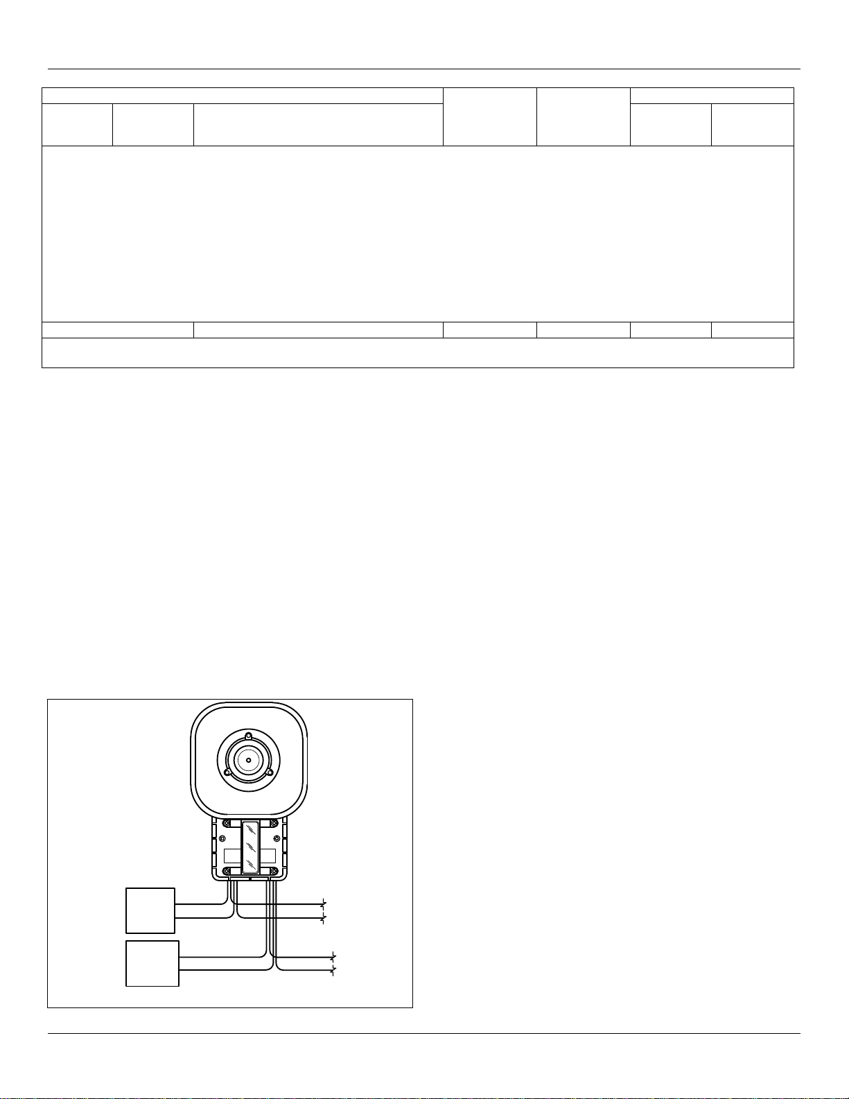
1. Tone Card Installation
290A3363
RED
24 VDC
STROBE
POWER
BLK
+
-
RED
BLK
RED
BLK
RED
24 VDC
SPEAKER
POWER
BLK
+
-
Figure 2. Typical Tone Card Installation Wiring
Tone Card Sound (Model UTC) Audibility
Selection Name Description
Audible
Frequency
(Hz)
Repetition
rate
(cycles/min)
dB(A)
Sound
Power
UL dB(A)
Sound
Pressure
TM1 Wail Conventional siren 550-1250 11 118.1 97.5
TM2 Yelp Rapid siren 550-1250 3.3 Hz 118.0 97.4
TM3 Hi-Lo Alternating high and low 560 and 760 50 116.9 96.3
TM4 Bell Bell, struck repeatedly 800 50 115.8 95.2
TM5 Yeow Descending high to low, repeated 1300 and 550 36 118.0 97.4
TM6 Horn Steady horn 470 Continuous 112.2 91.6
TM7 Beep Slow intermittent horn 470 50 110.8 90.2
TM8 Stutter Rapid intermittent horn 470 5 110.3 89.7
TM9 Slow Whoop Slow ascending, low to high – repeated 420 and 1160 15 116.1 95.5
TM10 Temporal
Slow Whoop NFPA coded slow whoop (fire alarm use only) 420 and 1160 15 113.9 93.3
Connector card model Rated voltage
PTCK25 25 VRMS 112.4 97.8
PTCK70 70 VRMS 112.2 97.6
Table 2. Tone and connector card ratings for Model ASHP

ASHP PowerTone®Amplified Speaker Document #256880
- 3 -
a. See figure 2. Connect the device’s red (+) leads to the power
source positive (+) lead. Connect the device’s black (-) leads to
the power source negative (-) lead.
b. Plug the desired tone card into the socket as shown in figure 3.
c. To ensure a proper seal, be sure that the neoprene rubber
cover gasket is properly seated in the housing groove and
reinstall the housing cover.
2. PTCK Connector Kit Installation
WARNING
Property damage, serious injury, or death could occur if independent
conductors are terminated together; both wiresof the same polarity must
be used as two separate connections. NFPA 72 requires that the wires
be terminated independently to provide electrical supervision of the
connection, for both the 24 Vdc speaker power and 25 VRMS or 70
VRMS audio lines.
a. See figure 2. Connect the device’s red (+) leads to the power
source positive (+) lead. Connect the device’s black (-) leads to
the power source negative (-) lead.
b. Plug the desired PTCK connector card (purchased separately)
into the socket as shown in figure 3.
c. Connect the white leads from the connector card to the audio
input and outputs.
NOTE
Check with authority having jurisdiction for proper application of EOL
resistor and power supervision relay required (see figure 4).
d. To ensure a proper seal, be sure that the neoprene rubber
cover gasket is properly seated in the housing groove and
reinstall the housing cover.
3. Model ASHP (with Strobe Light Option).
DANGER
A high voltage shock hazard may be present inside the strobe light, even
if power is not connected. It is recommended that strobe light NOT be
opened. If access to the printed circuit board assembly is required
(removal or replacement of damaged unit), disconnect unit from power
source and wait 5 minutes.
a. See figure 2. Connect the strobe light’s red (+) lead to the
power source positive (+) lead. Connect the strobe light’s black
(-) lead to the power source negative (-) lead. If independent
control of the strobe light(s) is not needed, the leads may be
joined with the ASHP’s power leads.
WARNING
Property damage, serious injury, or death could occur if independent
strobe conductor wires are terminated together; both wires of the same
polarity must be used as two separate connections. NFPA 72 requires
that the wires be terminated independently to provide electrical
supervision of the connection.
290A3362
A C
B
1-13/16 .201 DIA. 2 HOLES
(MOUNTING)
2-9/16
7/8 DIA. CONCEALED CONDUIT KNOCK OUT
MOUNTING (IN REAR OF HOUSING)
2-3/4
COLLAR
NUT
2 x 1/2-14 NPT
5-5/8
13/16
3-3/8
INCHES MM
A
B
C
206
302
203
8-1/8
11-7/8
8
1/2" CONDUIT PLUG
SUPPLIED
2
Figure
1
. Model ASHP Dimensions
290A2627-10B
VOLUME CONTROL
AMPLIFIER BOARD
+RED RED
BLK
-BLK
INSTALL
TONE CARD HERE
P2
24VDC
290A3425
( HOUSING ) ( COVER )
AMPLIFIER BOARD POWER INPUT
+RED
-BLK
PCBASHP01A
REV.02
BLACK
WHITE RED
120 VAC MODEL
POWER
TO AMPL
120 VAC
INPUT
WITH DC
SUPERVISION
290A3361
BLACK (2 WIRES)
COMPONENTS ARE LOCATED INSIDE COVER OF SIGNAL.
RED (2 WIRES)
CR1
K1
+
-
T1
DC
SUPERVISION 120 VAC
Figure 3. Tone/Connector Card Installation
ASHP PowerTone®Amplified Speaker Document #256880
- 4 -
b. See figures 3 and 4. Perform the procedure in section Tone
Card Installation or section PTCK Connector Kit Installation as
applicable.
OPERATION/TESTING.
WARNING
Under certain conditions these devices are capable of producing sounds
loud enough to cause hearing damage. Adequate hearing protection
should be worn if standing within close proximity to device while testing.
Recommendations in the OSHA Sound Level Standard (29 CFR 1910)
should not be exceeded.
Property damage, serious injury, or death could occur if the housing is
not closed properly. To reduce possibility of explosion, housing cover
must be kept tight (all eight bolts fully tightened) while circuits are
energized.
After installation is complete, be sure to test the system to verify that
each amplified speaker operates satisfactorily. If it is found that the unit is
too loud for its location, an internal volume control can be adjusted.
Remove the housing cover and insert a slotted screwdriver with an 1/8”
blade into the hole shown in figure 3. Gently turn control to desired
loudness. Reinstall the housing cover.
After completion of initial system test, establish a program for periodic
testing of this device. Refer to NFPA 72, local Fire Codes and the
authority having jurisdiction for this information.
Provide a copy of these instructions for the Safety Engineer, system
operator(s) and maintenance personnel.
MAINTENANCE.
Periodically check this device to verify that there are no foreign
substances in, or in front of, the speaker which will reduce its
effectiveness.
Testing should be periodically performed. Refer to NFPA 72, local Fire
Codes and the authority having jurisdiction for information.
In the event a repair is required, be sure to refer to the Safety Message
To Maintenance Personnel before proceeding.
SERVICE.
This product is covered by a 5 year limited warranty. See warranty terms
and conditions for details.
The factory will service your equipment or provide technical assistance
with any problem that cannot be handled locally with satisfaction or
promptness.
If any unit is returned to factory for repair, it can be accepted only if we
are notified by mail or phone in advance of its arrival. Such notice should
clearly indicate service requested and give all pertinent information
regarding nature of problem and, if possible, its cause.
To get help with problems or questions not covered in these instructions,
contact:
Technical Service Department
Commercial Products Group (CPG)
2519 - 4th Avenue
Moline, IL 61265
(800) 521-8219
PowerTone is a registered trademark of Commercial Products Group.
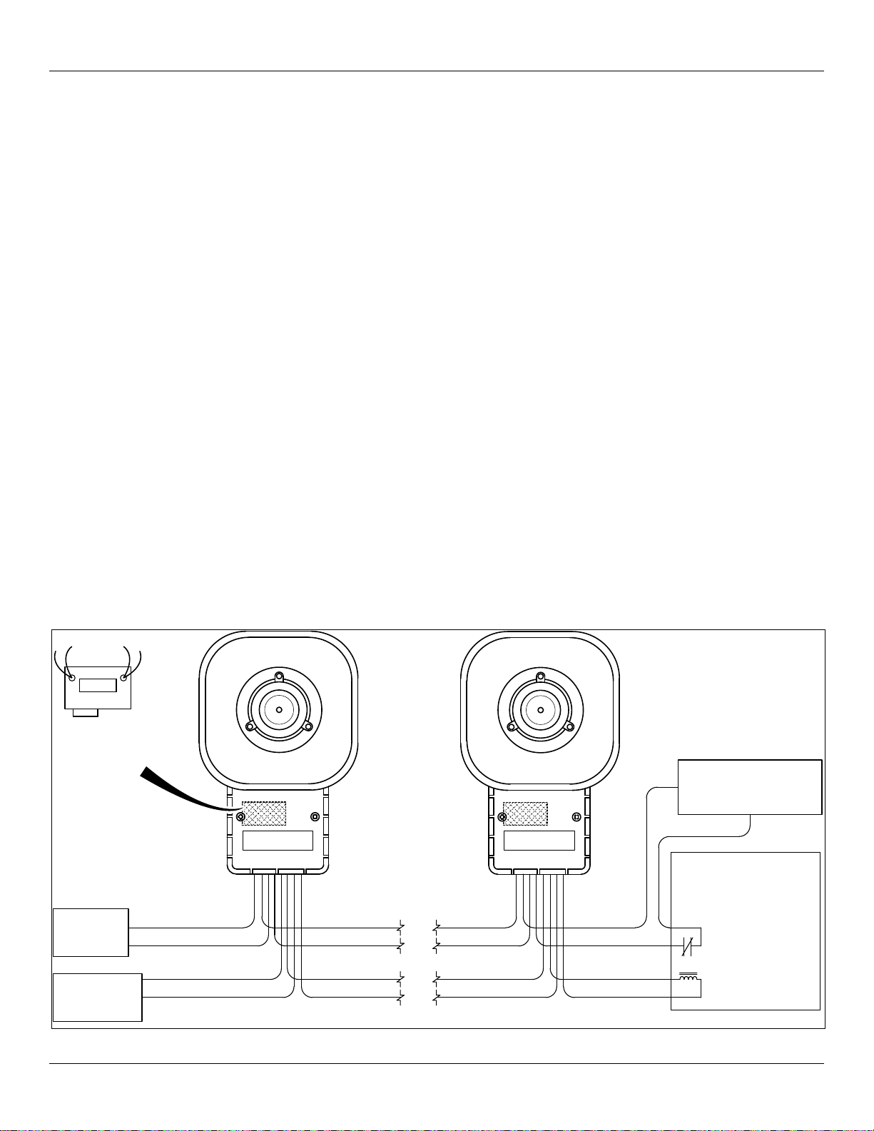
25 OR 70 VRMS
AUDIO
INTERNAL PTCK
CONNECTOR CARD
(25 OR 70 VRMS
SUPPLIED
SEPARATELY)
(SERIES B)
24 VDC
POWER
290A2627-12B
(+)
(-)
WHT
WHT
WHTWHT
WHT
WHT
WHTWHT
RED
BLK
RED
BLK
RED
BLK
RED
BLK
FOR 24 VDC USE:
POWER SUPERVISION
RELAY MODEL
A77-716-02 BY SYSTEM
SENSOR, OR MODEL R64
BY UNITED SECURITY
PRODUCTS OR MODEL
PAM-2 BY AIR PRODUCTS
& CONTROLS LTD.
END OF THE LINE DEVICE
RECOMMENDED BY
CONTROL UNIT SUPPLIER.
FOR 120 VAC USE:
MODEL PAM-1, BY
AIR PRODUCTS &
CONTROLS LTD.
Figure 4. Typical connector card (PTCK) installation wiring


