C+R Automations LUDES AIR 270 Parts list manual

1
LUDES AIR 270
ASSEMBLY AND OPERATION INSTRUCTIONS

2
Safety Instructions
!!! Caution: Areas which can only be opened by using a tool must
to be considered as maintenance areas. Unauthorized opening
may be dangerous for the operator !!!
- This device is not to be operated by people with reduced physical, sensorial or
mental capabilities or lack of experience and / or knowledge (including children).
- This device is a technical tool to be used in closed areas or receptacles.
- Protect your eyes and skin from UV light. In a very short period of time UV-C
radiation generates severe sunburn and painful conjunctivitis in the eyes.
- Please take into consideration that the equipment’s operator is responsible for all
people being inside the room.
- UV radiation can be screened by means of current glass, transparent plastic
materials such as macrolon, as well as by practically any other type of non-
transparent material.
- As to reduce a possible dazzling effect, the use of tinted protective goggles is
being recommended.
- AdditionalinformationregardingUVltersmaybeobtainedfromthenorm
“EN 170 – Personal Eye Protection”.
- Quartz glass is permeable to UV radiation and must not be used for personal
protection.
- Please pay attention to the fact that materials which are not sturdy enough will be
damaged by UV-C.
- The unintentional use of the device or a damaged housing may cause the spill of
dangerous UV-C radiation.
- Devices showing evident damages must not be operated - please contact the
manufacturer in case!
- Before opening the device, present operating and maintenance instructions should
be read.
3
general information
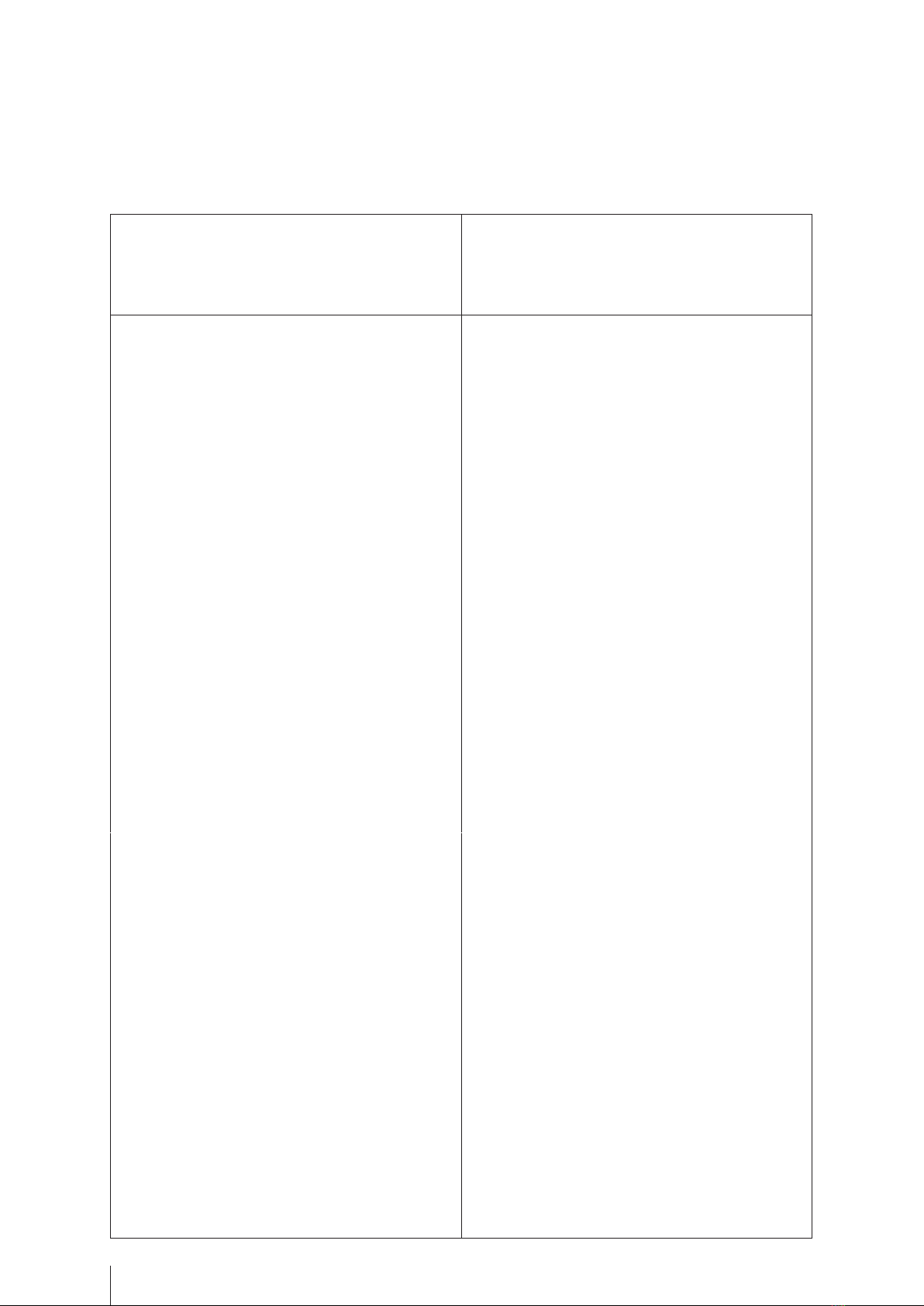
- The UV plant LUDES AIR 270 needs to be installed and operated in a
horizontal position.
- The scope of delivery contains the assembly system.
- Assemblyshouldbecarriedoutbyauthorizedqualiedstaffonly.Thecurrent
electrical instructions (DIN 0100, BGR A3, BGV A3, u.a.) should be considered.
Assembly Instructions
1st step: preparation of the UV system
- Close the LUDES AIR 270 plant.
- Please make sure that the housing cover is fixed at the basic unit at the mounting
points using the 6 bolts.
2nd step: assembly of the UV system at the ceiling
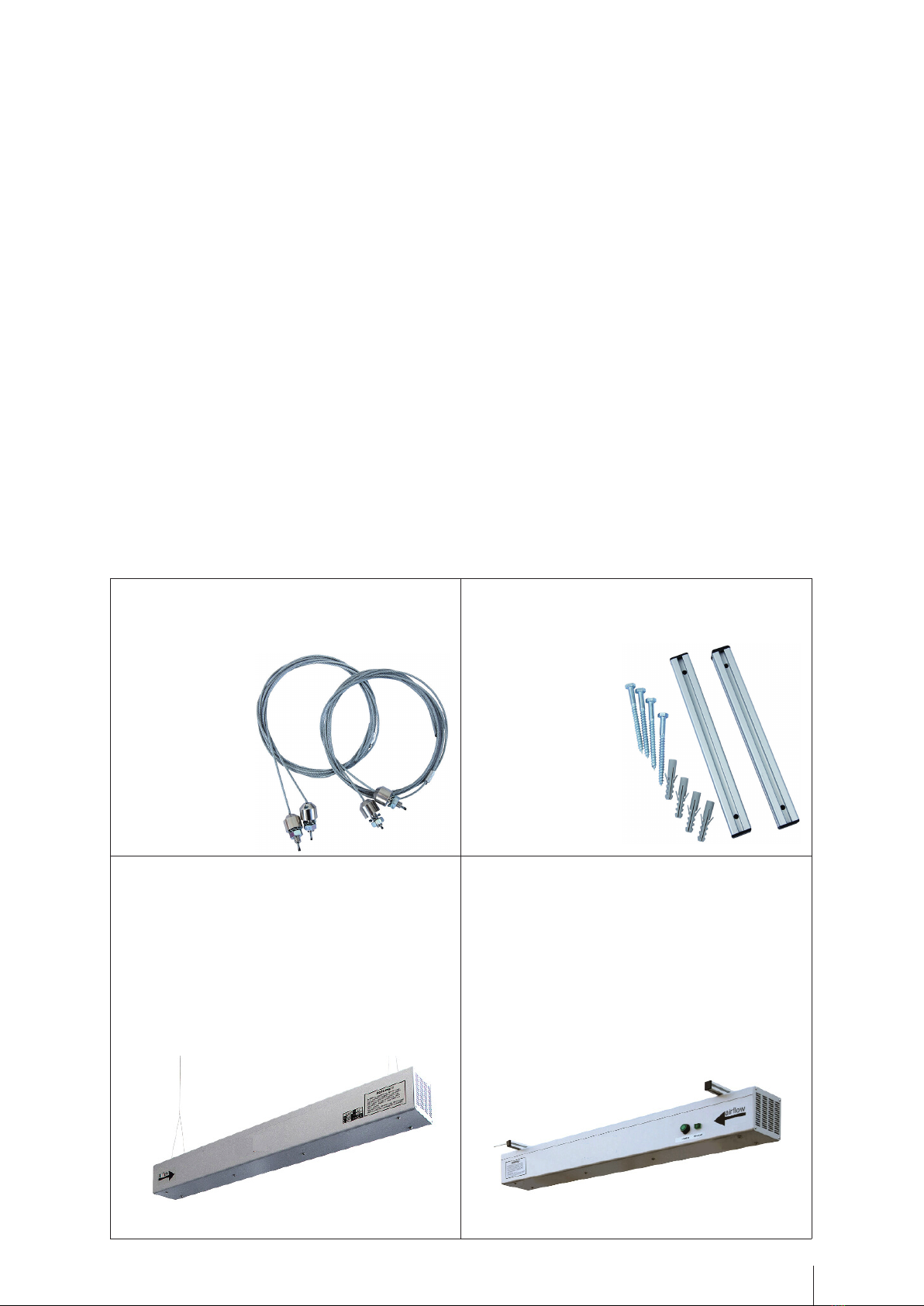
Option 1:
wire suspension
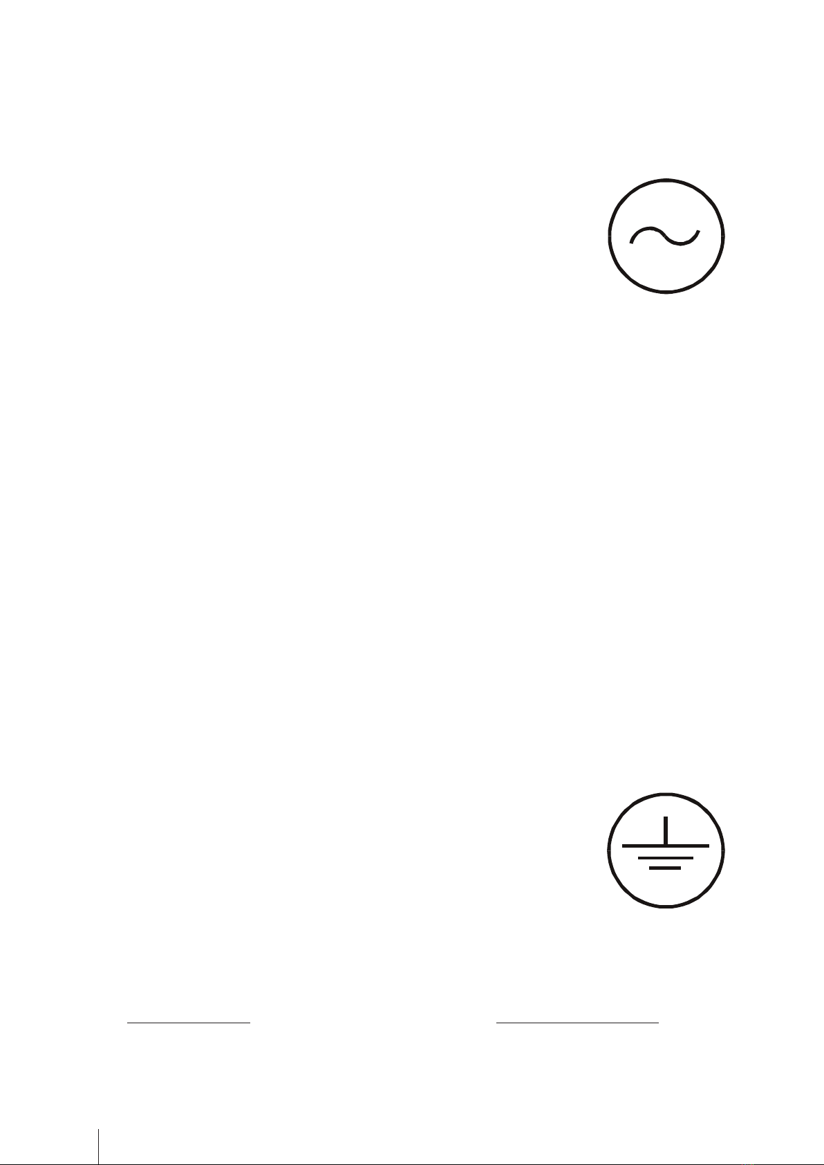
Option 2:
Mounting rack
• fixing of the two wire suspensions at
the ceiling
• hitching up the system at the wire
suspension at using the prepared
openings at the housing cove
• ensuring that the mounting rack is
xedatthehousingcover
• xingthesystemattheceilingusing
the 4 bolts
4
scope of delivery:
- complete LUDES AIR 270 housing
- 230 V AC 50Hz power supply for UV ray supply voltage
- 3x UV-C lamp 90 W
- mounting instruction for the complete system
intended use:
- This product is intended for air disinfection and:
° has to be operated with 230 VAC 50Hz power supply
° has to be used in both humid and dry environments;
° shall not be exposed to severe mechanical strain or heavy pollution;
° shallnotbealteredormodied.
installation and operation:
- The housing should be installed horizontally (see assembly instructions).
- A direct connection of the system to the existing electrical installation is generally
possible.
- The front cover (fan guard) may only be used for lamp replacement and then
decreased only in the off state of the system (safety rules). An operation of the
system without end cover (fan guard) is not allowed!
connecting the UV lamp:
- Introduce the cut-in unit’s power plug into the 230V safety power outlet. Thereafter,
the UV lamp’s functioning has to be visually controlled.
- The green lights next to the main switch should light up after a short time. The
three UV lamps and the fan are turned on.
connection type: safety plug
protection class: I
description of failures:
- Incaseofunsufcientdisinfectionorpoorperformance,theequipmenthastobe
inspected.
possible causes: measures to be taken:
° contamination of the immersion tube system ° cleaning
° green indicator light is off ° main switch
° lamp aging ° lamp replacement
Operation Instructions

5
- More electrical work is not carried out.
Please contact the manufacturer or distributor !!!
operating time counter – OTC
**ThischapterisonlyrelevantiftheOTCcongurationhasbeenchosen**
- The system operates as a time counter. The counting starts if the system is switched
on. With every switch on the so called “Startup Procedure” is carried out.
To ensure operability the LED’s flashes one after another: red, yellow and green 1se-
cond each. Moreover the procedure can be interrupted to realize a reset of the counter.
- Themonitoringsystemisdesignedasatrafclight.TwothresholdsforUVinten-
sity have been saved:
° As long as the operating time is below 95% of the guaranteed life time the green
LED is illuminated.
° If the operating time exceeds 95% of the guaranteed life time the yellow LED is
illuminated (pre alert).
° If the operating time exceeds the guaranteed life time the red LED is illuminated
(main alert).
- Adjustment of the system after replacement of the UV lamps:
1. The unit is turned on –
please wait until the UV lamp has started and the LED’s have been illuminated
2. press and hold the “Reset” button (approx. 2 seconds)
3. release the „Reset“ button
4. red LED is illuminated once – during illumination of the yellow LED the „Reset“
button is to be pressed and hold again (approx. 2 seconds)
5. release the „Reset“ button
6. red LED is illuminated once – during illumination of the yellow LED the „Reset“
button is to be pressed and hold again (approx. 2 seconds)
7. release the „Reset“ button
8. the “startup” procedure is carried out
9. the system is adjusted and the green LED is illuminated.
maintenance - lamp replacement:
- In principle, the UV lamps should be replaced after one year or about 10,000
operating hours have elapsed.
remark:
° Under the UV light influence and independently of the lamp age, the radiator
socket will turn brownish although its functioning will not be influenced by it.
6
procedure
Option 1:
after removing it from the ceiling
(recommended option)
Option 2:
directly at the ceiling
• disconnect the equipment
• pull the power plug
• remove the UV system from the ceiling
via:
... releasing the wire suspension
... or releasing the mounting rack
• open the housing via removing the
housing cover
• now you can pull the immersion tube
systems from the clamps
• detach cable screwing
• pull the polyethylene-made protecting
cap backwards
• detach the 4-pole plugs from the lamps
• remove the lamps from the quartz
tubes
• when doing so, just touch the socket
(caution: could be hot!)
• fingerprints on the lamp’s tube are to
be removed with an alcohol-soaked
cloth or the Service KIT
• disconnect the equipment
• pull the power plug
• the lamp replacement is done on
the side on which at the note and
type of signs of the
located
• there is the immersion tube head
• unlock the 4 screws at the front side
• after the front side has been un-
screwed, you can the cable gland on
the PE protective cap slightly remove,
so you can move the cable
• now you pull the complete tube sys-
tem as far out from the system until
the tube head is just outside of the
prole(aboutonehandwidth)is
located.
• hold the complete system with the
other hand
A further addition pulling should be
avoided !
Reinstalling the UV lamps:
• introduce UV lamps through the stain-
less steel head into the quartz-made
cladding tube until the bottom has
been reached
• push transparent polyethylene-made
protecting cap up to the immersion
tube’s head sealing
• fasten lamp’s cable by means of cable
screwing and implement traction
relief
• push transparent polyethylene-made
protecting cap into the sealing of the
immersion tube’s head as far as it will
go
• put the immersion tube systems back
into the clamps
• detach cable screwing
• pull the polyethilene-made protecting
cap backwards
• detach the 4-pole plugs from the
lamps
• remove the lamps from the quartz
tubes
• when doing so, just touch the socket
(caution: could be hot!)
•ngerprintsonthelamp’stubeare
to be removed with an alcohol-
soaked cloth
or the Service KIT

7
• close the system via fixing
the housing cover at the basic unit
• go ahead with step 1/2
of the assembly instruction
Reinstalling the UV lamp:
• introduce UV radiator through the
stainless steel head into the quartz-
made cladding tube until the bottom
has been reached
• push transparent polyethylene-made
protecting cap up to the immersion
tube’s head sealing
• fasten lamp’s cable by means of
cable screwing and implement trac-
tion relief
• push transparent polyethylene-
made protecting cap into the sealing
of the immersion tube’s head as far
as it will go
• now the complete immersion tube
system is pushed back into the pro-
le;holdthecompletesystemwith
the other hand
• the cable is again slightly bent so
that the fan guard be screwed easily
liability and warranty:
- For warranty claims, we shall only be liable under the national legal warranty.
- The general terms and conditions of C+R Automations- GmbH are holding.
- We explicitly point out that the warranty does not apply to damage caused by:
° operatingfailureinconsequenceofinsufcientfollowingthisuserinformation
° operating with spare parts such as lamps and ballasts which are no
original parts.
° installation of incompliant accessories
° incorrect operation / installation
° removing, manipulating or non-insertion of protective devices
° improper execution of maintenance
° wear and non-exchanging of wear agents.
summary of materials:
- stainless steel V4A (1.4571)
- AlMg

8
C+R Automations- GmbH
Nürnberger Straße 45
90513 Zirndorf
Tel. +49 (0)911 656587-0
www.crautomation.de
Table of contents


