manuals.online logo
Brands
  1. Home
  2. •
  3. Brands
  4. •
  5. CQR
  6. •
  7. Security System
  8. •
  9. CQR SC517 Series User manual

CQR SC517 Series User manual

Surface mounted magnetic contact.
Compact design
Four terminals.
Double pole or EOL configuration.
Suitable for domestic and commercial alarm circuits.
Suitable for double door applications.
Can be used in installations up to and including grade 2.
High impact polymer construction.
41
CQR Security. 125, Pasture Road,Moreton, Wirral. CH46 4TH, United Kingdom
Tel: +44 (0) 151 606 9595 Support: +44 (0) 151 606 6311 email: info@cqr.co.uk Web http://www.cqr.co.uk
Environmental Advice.
This product is covered by current WEEE regulations. Please consider the effect on the
environment when disposing of it. Do not put in a domestic waste bin. Only dispose of
at an appointed recycling centre.
Description
Operating and Installation
Instructions
RoHS compliant. SC517/*/MULTI/G2/EN Issue 03
This product is designed to meet the requirements of EN50131-2-6:2008
Security grade 2 , environmental class II
This compact surface mounted magnetic contact can be used in most security systems up to
and including grade 2 as specified in EN50131-1: 2006 and is certified to EN50131-2-6:2008
and environmental class II (for use indoors) by Telefication. It operates as a normally closed
circuit going open when the magnet housing is moved away from the contact housing.This
contact can be used on windows and doors to detect the unauthorised entry of an intruder.
A number of applications are shown over.The contact is also tamper protected against
removal from its mounting surface.
SC517/*/MULTI/G2/EN Magnetic Surface Contact.
* colour varies
X
Y
Min Close 25mm
Max Open 40mm
Min Close 15mm
Max Open 25mm
Mounting on a ferrous surface will reduce these
figures, dependant on the material and thickness.
X
Y
Switch
Contact Material: Rhodium
Contact Rating: 500mA @ 12Vdc
Contact Resistance: 100 milliOhms
Temperature Range: -15° C to +40° C
Life Expectancy: >1,000,000 cycles
Housing
Material: High Impact Polystyrene
Contact Dimension (mm): 65 x 13 x 15
Contact Fixing (mm): 26mm centres
Magnet Dimension (mm): 65 x 11 x 13
Magnet fixing (mm) 26mm centres
Specifications
Type
A
B
D
E
I*
Colour Alarm Tamper
Control Panel
Green 1K 1K
Red 4K7 2K2
Orange 5K6 5K6
Purple 6K8 4K7
Varies 4K7 4K7
Honeywell, Ademco Microtech
Scantronic, Menvier, Pyronix PCX (12, 22, 44,128 VID),Texecom, Castle CareTech G3 Plus.
DSC
Guardtec
Pyronix Matrix, PCX SMS, 134, 256.
Control panel types available on this model.
Approximate Operating Distances (mm) with reed
closest to the arrow and using Non Ferrous Surfaces
* Please note that type I (4K7 : 4K7) is achieved by selecting the alarm link of type B and the tamper link of type E
3
2
Features
Tamper Connections
Alarm Connections
Tamper Switch
Fixing Hole
Door 1 Door 2
Wiring Configurations
Mounting Instructions
Mount the contact housing using the fixing holes as shown in the diagram. Please see the
mounting configurations to ensure that the contact is mounted in the most suitable location.
Terminate the pcb as shown in the diagrams and cut the appropriate links. Refit the pcb into
the casing with the pcb nearest to the arrow and the tamper switch facing outwards, this will
ensure maximum operating gap.The seperate anti tamper plate must be secured to the
mounting surface with its own screws before the main case is fitted and finally secured into
place. Mark out the position of the magnet housing and secure in place with the screws
provided.
Cable Entry
Fixing Hole
Contact Housing
Magnet Housing
Cable Entry
Snap out
Casement Windows Factory Windows Patio Doors
Residential Doors Sash Windows Wood Awning Windows
Suitable Applications and Fixing Points
Recommended fixing points
Circuit Board
Anti -Tamper Plate
EOL Selection Links
Fixing Hole
Fixing Hole
Fixing Hole
Fixing Hole
Door 1
Cut links L1 and L2
Connect T1 to tamper zone
Connect T3 to alarm zone
Fully Supervised (Panel type A illustrated)
Cut appropriate resistor links
(1K 1K illustrated).
EOL Circuit = T1 and T4
Alarm EOL
Tamper EOL
SW1
TAMPER
TAMPER
ALARM
SW2
SW3
EOL
Circuit
T1 T2 T3 T4
TAMPER ALARM
6K8
5K6
4K7
1K
4K7
5K6
2K2
1K
L1
L2
RoHS
Double Pole
Cut links L1 and L2
Alarm Circuit = T3 and T4
Tamper Circuit = T1 and T2
Alarm
Tamper
SW1
TAM PER
TAMPER
ALARM
SW2
SW3
T1 T2 T3 T4
TAMPER ALARM
6K8
5K6
4K7
1K
4K7
5K6
2K2
1K
L1
L2
RoHS
SW1
TAM PE R
TAM PE R
ALARM
SW2
SW3
T1 T2 T3 T4
TAM PE R ALARM
6K8
5K6
4K7
1K
4K7
5K6
2K2
1K
L1
L2
RoHS
SW1
TAM PE R
TAMPER
ALARM
SW2
SW3
T1 T2 T3 T4
TAMPER ALARM
6K8
5K6
4K7
1K
4K7
5K6
2K2
1K
L1
L2
RoHS
SW1
TAMPER
TAMPER
ALARM
SW2
SW3
T1 T2 T3 T4
TAMPER ALARM
6K8
5K6
4K7
1K
4K7
5K6
2K2
1K
L1
L2
RoHS
SW1
TAMPER
TAMPER
ALARM
SW2
SW3
T1 T2 T3 T4
TAM PE R ALARM
6K8
5K6
4K7
1K
4K7
5K6
2K2
1K
L1
L2
RoHS
Tamper
Alarm
Interconnections
Connect T2 door 1 to T1 door 2
Connect T4 door 1 to T3 door 2
Door 2
Cut links L1 and L2
Connect T2 to tamper zone
Connect T4 to alarm zone
Double Pole Double Door
Door 1 Door 2
Door 1
Cut links L1 and L2
Cut appropriate tamper link
(2K2 illustrated)
Connect T1 to EOL Zone
Interconnections
Connect T2 door 1 to T1 door 2
Connect T4 door 1 to T3 door 2
Door 2
Cut link L1 only
Cut appropriate alarm link
(4K7 illustrated)
Connect T4 to EOL Zone
Fully Supervised Double Door
Panel Type B illustrated
Tam per
Links
Alarm
Links
Mounting Configurations
PCB should be nearest to the arrow and magnet.
Spring should point out of the case.
Spring Pocket

Other CQR Security System manuals

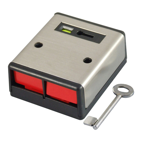
CQR PADP2/SS/G1 User manual

CQR

CQR PADP2/SS/G1 User manual

CQR PADP2 Series User manual

CQR

CQR PADP2 Series User manual

Popular Security System manuals by other brands

Cobra P1703-141 manual

Cobra

Cobra P1703-141 manual

Electronics Line SecuPlace Quick user guide

Electronics Line

Electronics Line SecuPlace Quick user guide

Numera Libris quick start guide

Numera

Numera Libris quick start guide

Alderon Industries VersAlarm I/O user guide

Alderon Industries

Alderon Industries VersAlarm I/O user guide

Texecom Premier Elite Ricochet Kits quick start guide

Texecom

Texecom Premier Elite Ricochet Kits quick start guide

Whelen Engineering Company ECE 360 Class 1 installation guide

Whelen Engineering Company

Whelen Engineering Company ECE 360 Class 1 installation guide

Pulsar 7/TRP40/DSPR/S Assembly instructions

Pulsar

Pulsar 7/TRP40/DSPR/S Assembly instructions

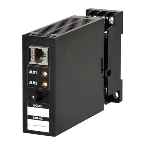
YOKOGAWA JUXTA VJAK user manual

YOKOGAWA

YOKOGAWA JUXTA VJAK user manual

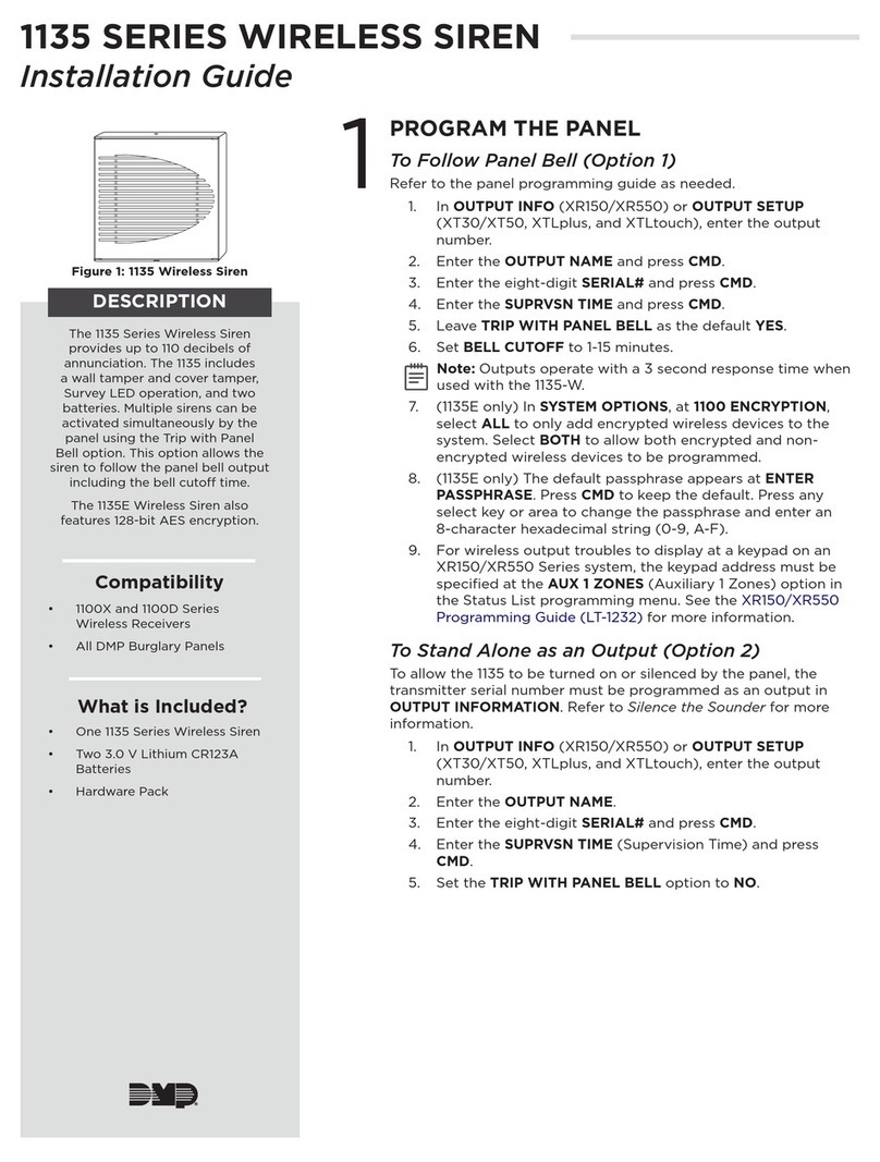
DMP Electronics 1135 Series installation guide

DMP Electronics

DMP Electronics 1135 Series installation guide

DSC PC1150 instruction manual

DSC

DSC PC1150 instruction manual

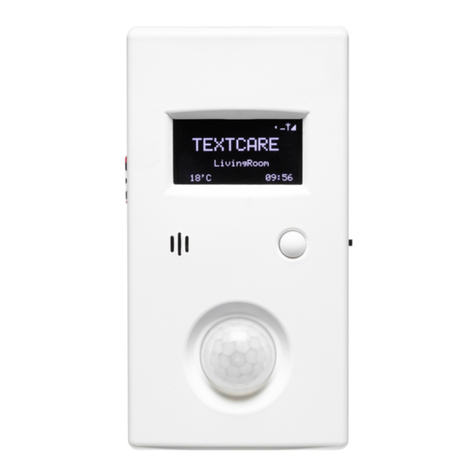
TEXTCARE Main Sensor troubleshooting guide

TEXTCARE

TEXTCARE Main Sensor troubleshooting guide

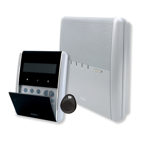
Risco Agility user manual

Risco

Risco Agility user manual

SecurityMan AIR-ALARM II SERIES user manual

SecurityMan

SecurityMan AIR-ALARM II SERIES user manual

Louroe Electronics TLMC-W instructions

Louroe Electronics

Louroe Electronics TLMC-W instructions

Honeywell TCPA2B installation instructions

Honeywell

Honeywell TCPA2B installation instructions

Schlage Schlage 1-877-288-7707 brochure

Schlage

Schlage Schlage 1-877-288-7707 brochure

Zoom Dialer 26 Installation and user guide

Zoom

Zoom Dialer 26 Installation and user guide

Telguard TG-4 Installation and operation instructions

Telguard

Telguard TG-4 Installation and operation instructions

manuals.online logo
manuals.online logoBrands
  • About & Mission
  • Contact us
  • Privacy Policy
  • Terms and Conditions

Copyright 2025 Manuals.Online. All Rights Reserved.